Project 1 _Creating an Architectural plan for the provided plot size and develop relevant basic structural drawings
Project 1 _Creating an Architectural plan for the provided plot size and develop relevant basic structural drawings
Jagadeep.M.M
AIM:
To creating an Artchitectural plan for the provided plot size & develop relevant basic structural drawings.
INTRODUCTION:
- Architectural drawing is simply the technical drawing of a house ,a building or any kind of structure. Technical drawings are graphic representation such as lines and symbols that follow specific conventions of scale & projection. They may use them to indicate the overall appearance, inside or outside the building.
Architectural drawing:
- Architectural drawing for Floor plan.
- Architectural drawing for Elevation.
- Architectural drawing for Section.
Structural drawing:
- Structural drawing for beam.
- Structural drawing for column.
- Structural drawing for footing.
PROCEDURE:
Architectural drawing:
1. Architectural drawing for Floor plan.
- Open autocad softwere, type QNew incommand box,press enter.
- Select default setting as imperial setting.
- Drawing units setting as length=(Engineering),precision=0'0.0", Ok
- Drawing limits setting as, specify the lower left corner=enter,upper right corner=100',100',enter.
- Type the command box Dimension style manager & press enter.
- enter modify-enter primary units-unit format=Engineering, precision=0'0.0",enter Ok.
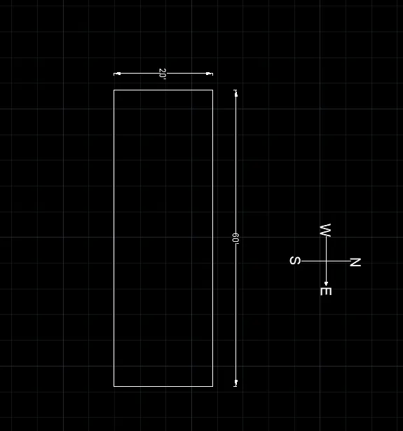
- Give the size of the plot using the rectangle command & offset for the thickness of the wall.
- Give the orientation of the plot by making the east direction.
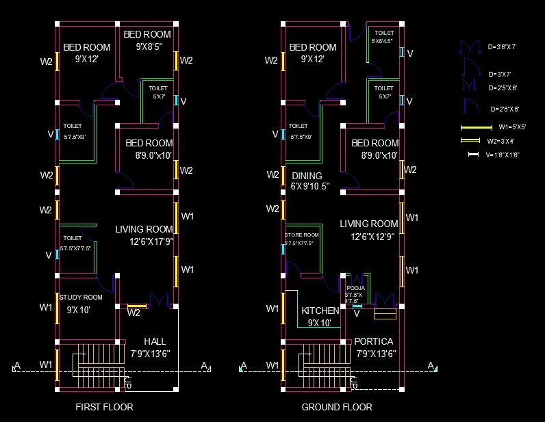
- Now we draw the groung floor:
- First we plot the size of the drawing 60'X20'.
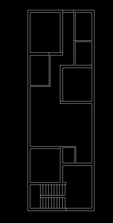
- give the inside offset as 9" of the wall thickness.
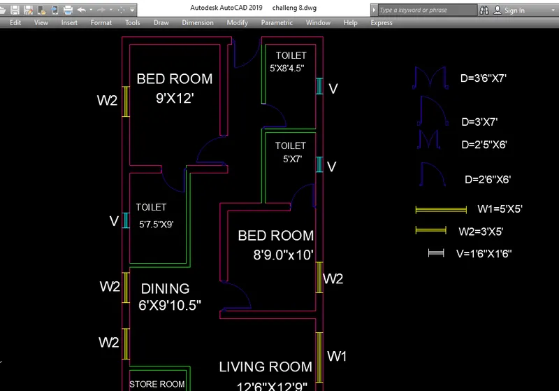
- use the offset command draw the bed room of the size 9'X12'.
- give the outside offse of 9" wall.
- give the offset of below the horizontal direction 5'7.5"X9' attached toilet in above the bed room.
- give the offset of 3'4.5" in right direction.
- give the offset of 4.5" in vrtical direction & draw the toilet of the size 5'X8'4.5".
- give the offset of 4.5" below & again give the offset of 5'X7' of the toilet.
- give the offse of 9" below & give the offset of horizontal & vertival direction of the bed room size 8'9"X10'.
- now give the offset of 4'9" is the living room & dining hall are below the bed room & again give the offset of 4.5" in left side.
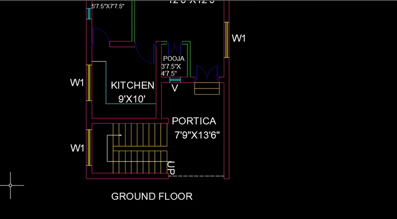
- To draw the store room of the size 5'7.5"X7'7.5" ok
- To draw the kitchen 9'X10' & give the thickness of the wall 9" enter.
- Draw the pooja in right side give the offse of 3'7.5"X4'7.5" enter give the wall thickness as 4.5".
- Now draw the stair case the dimension of the size is 10'9"X7'.
- Stair dimension thtead-10" , rise-6" & width is 3'2" ,number of steps-19.
- give the landing is 3'.
- give the portico dimension of right side 7'9"X13'6" enter.
- Now we draw the first floor:
- copy the ground floor plan & we make few changes.
- The kitchen is replaced with the study room & dimension will be same.
- The pooja room will be removed in this place.
- NW toilet will be changed bed room size of 9'X12'
- Now we create the door & windows & make the blocks.
- Assume the door size as D=3'6"X7'(double door), D1=3'X7', D2=2'5"X6'(double door),D3=2'5"X6'.
- Assume the window size as W1=3'X5', W2=5'X5', V=1'6"X1'6".
- Now insert the dimension using dimension command.
- insert the text using text command.
- give the layer using layer commad.
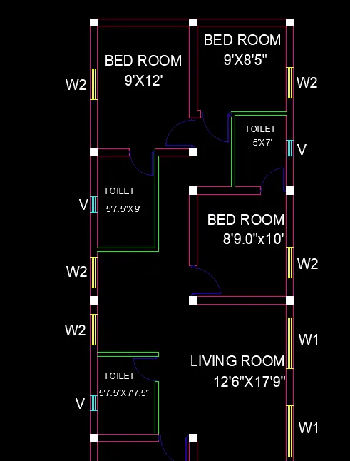
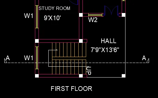
RESULT:
2. Architectural drawing for Elevation.
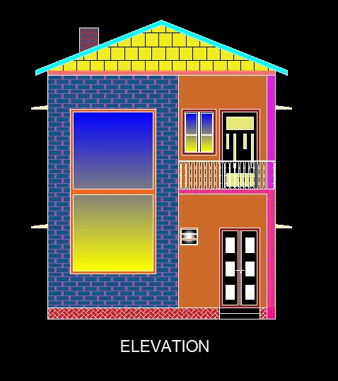
- Now project the lines to draw the elecation.
- Project the wall lines to the top & draw the vertical lines.
- offset 1' for the plinth level & 10' for the ground floor & 5" for the slab thickness & 10' for the first floor.
- We draw the door,windows & ventilator & give the height of 7',4'& 1'6" as required.
- Trim the unwanted line using trim command.
- create the top of the parapet wall.
- use the hatch command.
RESULT:
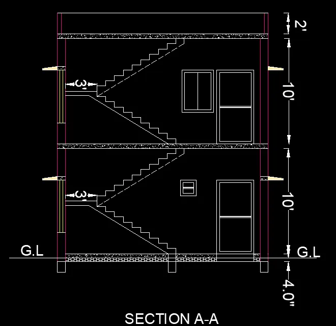
3. Architectural drawing for Section.
- Draw the section of ground floor plan.
- Project the line from the elevation for the height & from the section line of plan for the vertical memberes.
- Draw the door,ventilator which we see after cutting section line.
- To draw the section of stair case rise will be 6" ,thread is 10" & landing distance will be 3'.
- Now we draw the section of ground floor.
- Draw the ventilator& door,windows which we see after cutting section line.
- Now we draw the section of column size 9"X9".
- Place the column in all corner & intersection of wall & place it in layer.
- Copy the same for the first floor.
- In the section project the column from the plan to the section.
- Make the ground & plinth level.
- Hatch the lines using hatch command .
- use the dimension using the dimension command.
RESULT:
Structural drawing:
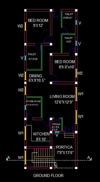
- Structural drawing for column.
- We consider column of size 9"X9".
- Column are placed in all corner & middle of the wall & intersection of walls wherever required.
- Copy the plan with column & delete all the windows.
- Draw the center grid line using line command.
- Delete all the walls & stairs.
- Now make the grid line as1,2,3,4,5,6,7,8 in the Y direction & A,B,C in the Xdirection.
- Create the circle & insert text into it.
- use the dimension using the command.
RESULT:
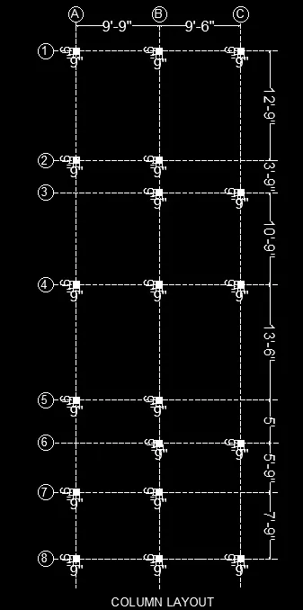
2. Structural drawing for beam.
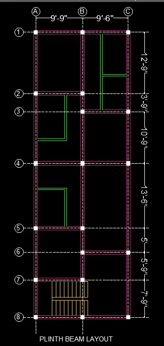
a)Plinth beam layout:
- For drawing plinth beam layout copy the ground floor plan with column.
- Plinth beam provided below all the walls.
- First connect column by beam of width 9" which are the primary beams.
- Now we draw the plinth- secondary beam & connect intrack walls as beam of width 4.5" beam to beam connections are secondary beams.
- Delete all the walls.
- use the dimension using dimension command.
RESULT:
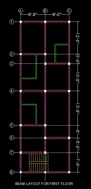
b)Beam layout for first floor:
- Now we draw primary beams of top floor.
- Copy the ground floor plan with column.
- Draw the beam of width 9" connecting all the column.
- Now draw secondary beam of top floor.
- For other wall beam of size 4.5" is provided at bottom portion of first floor.
RESULT:
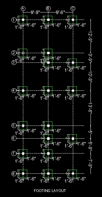
3. Structural drawing for footing.
- Isolated footing of size 3'X3' is provided.
- Create the rectangle with dimension 3'X3' & place the center of rectangle with the center of column.
- Make the footing for layer.
- Dimension the distance between footing & column.
RESULT:
I WILL ATTACHED THE ANOTHER All PDF RESULT FILE BELOW THE BROWSER OPTION