Project 1 _Creating an Architectural plan for the provided plot size and develop relevant basic structural drawings
Aim :- To Draw and Design the sketch of layout of a residence building
Introduction :- Draw and Design the sketch of layout of a residence building
- Plot Size: 60’x20’(18.3m x6m)
- Orientation- Facing East
- Develop the following:
- 1. Architectural Drawing (Floor Plan, Elevations, and Sections)
- 2. Structural Drawing (Column, Bean, Footing Plan)
Procedure :-
- First create a new AutoCAd file with metric settings.
- Set the limits by using LIMITS command, specify the left corner point and then the right corner point and enter zoom all and then press Z, enter then.
- draw the construction lines by using commands such as "XL-V" for vertical and "XL-H" for horizontal.
- Now using trim command trim the left side and the top side of construction line.
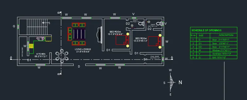
- Firstly we will draw Bedroom No.1 :-
- We will take an offset of 9" on both the sides of construction lines by using the offset command.
- Then take an offset in the horizontal direction and offset of 12' below of the construction horizontal line.
- Again give offset of 4.5" to both the lines to create thickness of wall.
- Trim the extra lines
- Now, we will draw Bedroom No.2 :-
- Now we will give an offset of 11'6" from the wall end of bedroom 1 in horizontal direction.
- Offset the wall of 9" on the righter end/side.
- Now Extending line 12' from Bedroom 1 to the line.
- Trim off the rest of the lines in Vertical and Horizontal direction.
- Delete if any excess line which are unable to trim.
- Drawing of Toilet 1:-
- Using the offset command, we will take offset at 4'6" downwards and then the offset
- of 4.5" on wall end.
- Now, extend the left wall side towards the line of 4'5" and the wall
- Now from that line offset 8'3" towards in X-direction and offset the wall of 4'5".
- Trim off the extra lines using trim command.
- Drawing of Toilet 2:-
- Using the extend command, we will extend the wall thickness of bedroom 2 to 4'6" line
- Now, the offset command, we will take offset at 8'1.5" in X-direction and alos 4.5" wall thickness
- Trim off the extra lines using trim command
- Drawing of Dining and Living room :-
- Use offset command and give 11' from the wall of tiolet and also give wall of 9"
- Now, using extend command, extend left wall of toilGive an offset of 8'7.5" to understand the partation between the dining and offset it as 4.5".
- Again by using offset command, give an offset of 6'8" from dining wall and also give an offset of 9" for the wall thickness
- Extend wall towards the line.
- Now again give an offset of towards in X-direction and offset the wall thickness of
- Drawing of Kitchen :-
- Again by using offset command, give an offset of 6'8" from dining wall and also give an offset of 9" for the wall thickness
- Extend wall towards the line.
- Now again give an offset of 11" towards in X-direction and offset the wall thickness of 9"
- Drawing of Staircase :-
- Size of thread =1"'
- Size of riser =6"
- Wall thickness of 9" from staircase room
- Dividing the Staircase = 3' from the front wall thickness
- Give an offset of 1' and draw stairs in plan view
- Draw 9" offset as there are 11 riser for 10 steps.
- trim the line between handrails and other line in dotted which indicate its 1st floor stairs, which will not be visible from groung floor plan view.
- For other side of stairs change line type to ISO dash and mark the direction of stairs.
- Drawing of Doors :-
- Create an opening for respective doors using the width given in the table of given question
- Draw doors by creating an hinge of 0.5" from the midpoint of both the wall, then drawing a circle with one point on the midpoint of hinged and other at midpoint of another hinged
- Drawing of Windows :-
- For LIving room take an offset 1'3" as given in the question figure
- Using line command draw a line of 6' from center of offseted line inside the wall thickness.
- Trim all the extra line using trim command
- Thus the Design and planning of Architectural Drawing
Now,
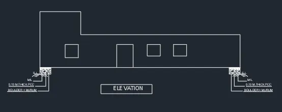
- For drawing of ELEVATION of the Architectural Drawing
The most commonly used command are
- Line
- Xl
- Offset
- Trim
- Copy
- Paste
- Extension
- Rectangle
- Linetype (lt)
- Arc
- Hatches
- Text
- Layers
- Mtext etc
Now,
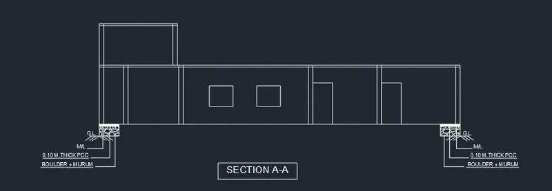
- For drawing of SECTION A-A of the Architectural Drawing
The most commonly used command are
- Line
- Xl
- Offset
- Trim
- Copy
- Paste
- Extension
- Rectangle
- Linetype (lt)
- Arc
- Hatches
- Text
- Layers
- Mtext etc
Now,
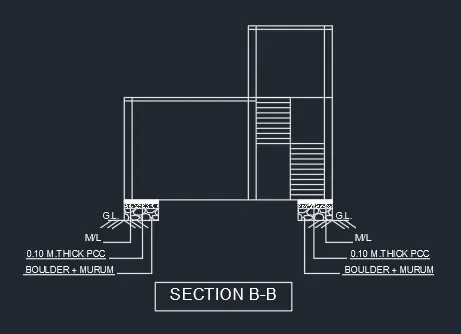
- For drawing of SECTION B-B of the Architectural Drawing
The most commonly used command are
- Line
- Xl
- Offset
- Trim
- Copy
- Paste
- Extension
- Rectangle
- Linetype (lt)
- Arc
- Hatches
- Text
- Layers
- Mtext etc
Now,
- For drawing of CENTER LINE PLAN AND COLUMN DETAILS of the Architectural Drawing
The most commonly used command are
- Line
- Xl
- Offset
- Trim
- Copy
- Paste
- Extension
- Rectangle
- Linetype (lt)
- Arc
- Hatches
- Text
- Layers
- Mtext etc
Now,
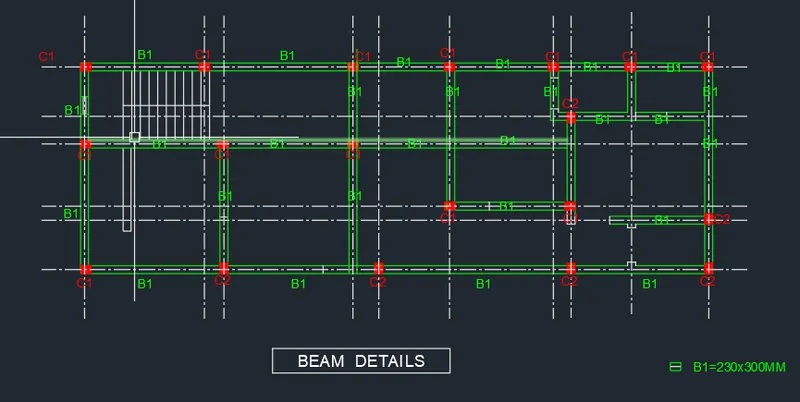
- For drawing of BEAM DETAILS of the Architectural Drawing
The most commonly used command are
- Line
- Xl
- Offset
- Trim
- Copy
- Paste
- Extension
- Rectangle
- Linetype (lt)
- Arc
- Hatches
- Text
- Layers
- Mtext etc
Now,
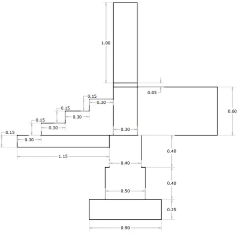
- For drawing of FOUNDATION DETAILS of the Architectural Drawing
The most commonly used command are
- Line
- Xl
- Offset
- Trim
- Copy
- Paste
- Extension
- Rectangle
- Linetype (lt)
- Arc
- Hatches
- Text
- Layers
- Mtext etc

Result :-
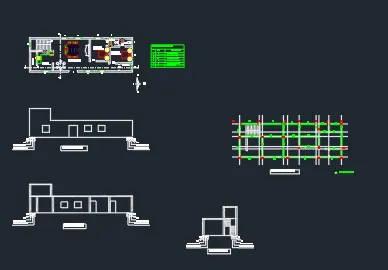
The detailing of the above figure is given in its every stage of drawing.