Project 1 - Controlling a DC motor using PWM and monitoring its Running status
Overview of the Project:
Implement a system on the simulator for controlling a DC motor using L293 motor driver, monitor its status and print the running status of motor on the LCD Display.
Goals:
- Implement a system on simulator for Controlling the DC motor using L293 motor driver.
- Displaying the running status of DC motor on the LCD display.
Key Highlights of the Project:
- The DC motor can be controlled by using L293 motor driver.
- The speed of a DC motor can be controlled by varying its input voltage, for doing this is to use PWM (Pulse Width Modulation).
- L293D IC is a typical Motor Driver IC which allows the DC motor to drive on any direction.
Deliverables of this project:
- Implement the system for controlling DC motor.
- Controlling the speed of the DC motor using PMW.
- Displaying the present running status of DC machine on LCD display.
Expected Outcomes:
- Implement a system on simulator to control a DC motor using PMW
- Monitoring the running status of the DC motor using L293 motor driver which allows the DC motor to drive on any direction.
- Running status i.e. on which direction the DC motor is running is to be displayed on the LCD screen
Aim:
- Implement a system on simulator to control a DC motor using PMW
- Monitoring the running status of the DC motor using L293 motor driver which allows the DC motor to drive on any direction.
- Running status i.e. on which direction the DC motor is running is to be displayed on the LCD screen.
Description:
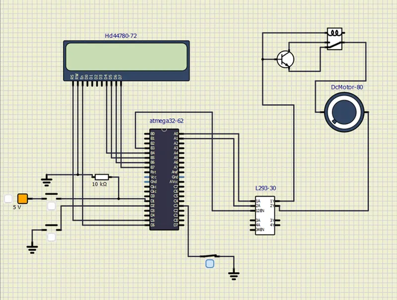
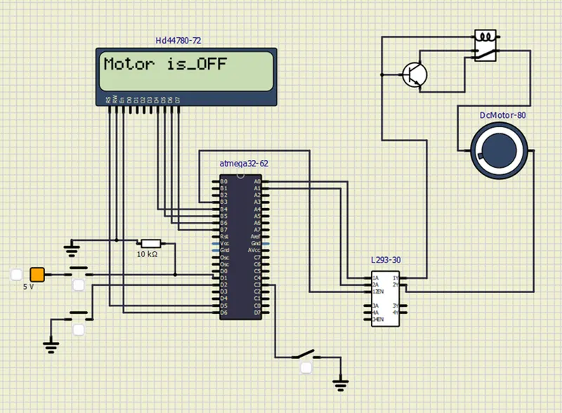
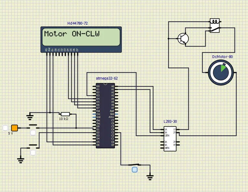
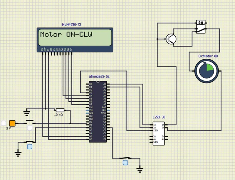
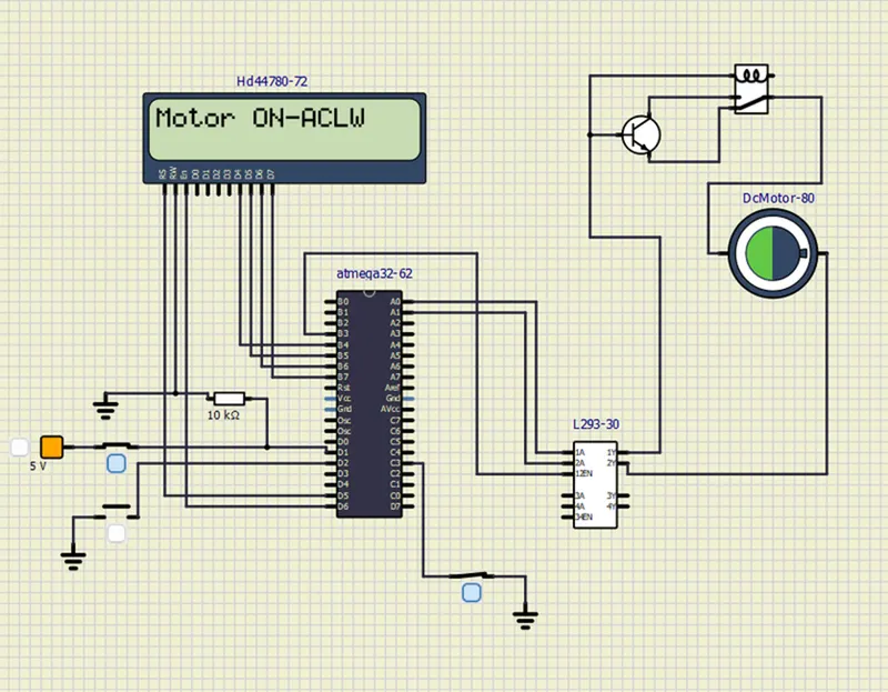
The goal of this project is to develop a simulation of a motor control system using the ATmega32 microcontroller and an L293 motor driver. The project aims to control the direction and speed of a DC motor while displaying its running status on an LCD module. The motor control system utilizes the L293 motor driver's input pins, specifically 1A and 2A, which are connected to A0 and A1 pins of the ATmega32 microcontroller. Additionally, the EN12 pin of the L293 motor driver is connected to the B3 pin of the ATmega32. This setup allows for bidirectional motor control and modulation of motor speed.
The motor's direction is controlled by interpreting the signals received from the ATmega32's pins A0 and A1, which correspond to the 1A and 2A inputs of the L293 driver. This configuration enables the motor to rotate clockwise, counterclockwise, or remain stationary. Moreover, the motor's speed is managed using Pulse Width Modulation (PWM) by adjusting the signal on pin B3, which is connected to the EN12 pin of the L293. This modulation allows for precise control of the motor's rotational speed.
To enhance user interaction, the project includes an LCD module that displays the current running status of the DC motor. The LCD provides real-time updates about the motor's direction and speed. User inputs, such as changing the motor's direction or adjusting its speed, are facilitated through the ATmega32's pins and are reflected in the LCD display.
The simulation involves implementing the motor control logic, interfacing with the L293 motor driver, configuring PWM for speed modulation, managing LCD communication, and handling user inputs. By combining these elements, the project showcases an integrated system that effectively controls a DC motor's operation, allowing users to observe and interact with the motor's behavior through the LCD display.
ATmega32 – 8 Bit AVR Microcontroller
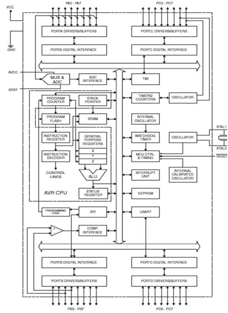
The AVR microcontrollers are based on the advanced RISC architecture. ATmega32 is a low power CMOS 8-bit microcontroller based on the AVR enhanced RISC architecture. AVR can execute 1 million instructions per second if cycle frequency is 1MHz.
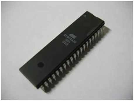
Key Features:
- Features
• High-performance, Low-power AVR® 8-bit Microcontroller
• Advanced RISC Architecture
– 131 Powerful Instructions – Most Single-clock Cycle Execution
– 32 x 8 General Purpose Working Registers
– Fully Static Operation
– Up to 16 MIPS Throughput at 16 MHz
– On-chip 2-cycle Multiplier
• Nonvolatile Program and Data Memories
– 32K Bytes of In-System Self-Programmable Flash
Endurance: 10,000 Write/Erase Cycles
– Optional Boot Code Section with Independent Lock Bits
In-System Programming by On-chip Boot Program
True Read-While-Write Operation
– 1024 Bytes EEPROM
Endurance: 100,000 Write/Erase Cycles
– 2K Byte Internal SRAM
– Programming Lock for Software Security
• JTAG (IEEE std. 1149.1 Compliant) Interface
– Boundary-scan Capabilities According to the JTAG Standard
– Extensive On-chip Debug Support
– Programming of Flash, EEPROM, Fuses, and Lock Bits through the JTAG Interface
• Peripheral Features
– Two 8-bit Timer/Counters with Separate Prescalers and Compare Modes
– One 16-bit Timer/Counter with Separate Prescaler, Compare Mode, and Capture
Mode
– Real Time Counter with Separate Oscillator
– Four PWM Channels
– 8-channel, 10-bit ADC
8 Single-ended Channels
7 Differential Channels in TQFP Package Only
2 Differential Channels with Programmable Gain at 1x, 10x, or 200x
– Byte-oriented Two-wire Serial Interface
– Programmable Serial USART
– Master/Slave SPI Serial Interface
– Programmable Watchdog Timer with Separate On-chip Oscillator
– On-chip Analog Comparator
• Special Microcontroller Features
– Power-on Reset and Programmable Brown-out Detection
– Internal Calibrated RC Oscillator
– External and Internal Interrupt Sources
– Six Sleep Modes: Idle, ADC Noise Reduction, Power-save, Power-down, Standby
and Extended Standby
• I/O and Packages
– 32 Programmable I/O Lines
– 40-pin PDIP, 44-lead TQFP, and 44-pad MLF
• Operating Voltages
– 2.7 - 5.5V for ATmega32L
– 4.5 - 5.5V for ATmega32
• Speed Grades
– 0 - 8 MHz for ATmega32L
– 0 - 16 MHz for ATmega32
• Power Consumption at 1 MHz, 3V, 25°C for ATmega32L
– Active: 1.1 mA
– Idle Mode: 0.35 mA
– Power-down Mode: < 1 µA
Overview:
The ATmega32 is a low-power CMOS 8-bit microcontroller based on the AVR enhanced RISC architecture. By executing powerful instructions in a single clock cycle, the ATmega32 achieves throughputs approaching 1 MIPS per MHz allowing the system designer to optimize power consumption versus processing speed.
Special Microcontroller Features:
- Six sleep modes: Idle, ADC noise reduction, power-save, power-down, standby and extended standby.
- Internal calibrated RC oscillator
- External and internal interrupt sources
- Power on reset and programmable brown-out detection.
All the 32 registers are directly connected to the Arithmetic Logic Unit (ALU), allowing two independent registers to be accessed in one single instruction executed in one clock cycle.
The power-down saves the register contents but freezes the oscillator. All other chip functions will be disabled until the next external interrupt arises. Asynchronous timer allows the user to maintain a timer based in power-save mode while the rest of the device is sleeping.
ADC noise reduction mode stops the CPU and all I/O modules except ADC and asynchronous timer. In standby mode, except crystal oscillator the rest of the device is sleeping. Both the main oscillator and asynchronous timer continue to run in extended standby mode.
ATmega32 is a powerful microcontroller because of its in system self-programmable flash on a monolithic chip, provides a high flexible and cost effective solution to many embedded control applications.
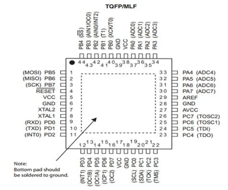
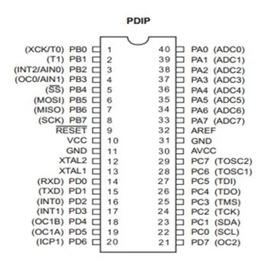
Pin Descriptions:
VCC: Digital voltage supply
GND: Ground
Port A (PA7-PA0): This port serves as analog inputs to the A/D converter. It also serves as an 8-bit bidirectional I/O port if the A/D converter is not used.
Port B (PB7-PB0) & Port D (PD7-PD0): It is an 8-bit bidirectional I/O port. Its output buffers have symmetrical drive characteristics with both high sink and source capability. As inputs, these are extremely pulled low if the pull-up resistors are activated. It also serves various special function features of the ATmega32.
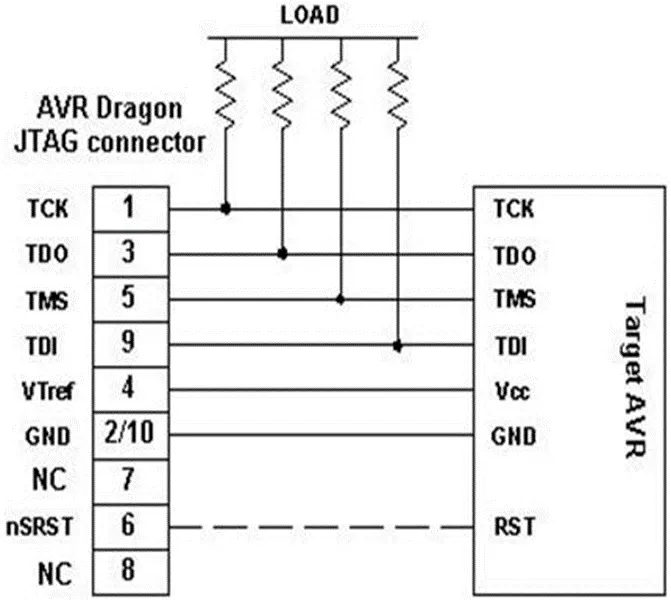
Port C (PC7-PC0): It is an 8-bit bidirectional I/O port. If the JTAG interface is enabled, the pull-up resistors on pins PC5 (TDI), PC3 (TMS), and PC2 (TCK) will be activated.
Reset: It is an input.
XTAL1: It is an input to the inverting oscillator amplifier and input to the internal clock operating circuit.
XTAL2: It is an output from the inverting oscillator amplifier.
AVCC: It is the supply voltage pin for Port A and A/D converter. It should be connected to VCC.
AREF: AREF is the analog reference pin for the A/D converter.
ATmega32 Memories:
It is having two main memory spaces data memory and the program memory space. In addition it features an EEPROM memory for data storage.
In System Programmable Flash Program Memory:
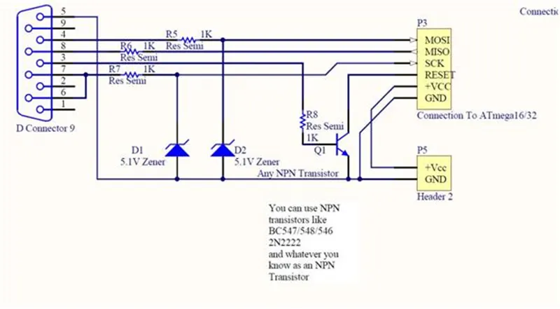
ATmega32 contains 32Kbytes on-chip in system reprogrammable flash memory for program storage. Flash is organized as 16k X 16 and its memory is divided into two sections Boot program section and application program section.
SRAM Data Memory:
The Register file, I/O memory, and the internal data SRAM are addressed by the lower 2144 data memory locations. The first 96 locations address the Register file and I/O memory, and the internal data SRAM is addressed by the next 2048 locations. Direct, indirect with displacement, indirect, indirect with pre-decrement, and in-direct with post decrement are the 5 different addressing modes for the data memory covering. The 32 general purpose registers, 64 I/O registers, and 2048 bytes of internal data SRAM are accessible by using these addressing modes.
EEPROM Data Memory:
It contains 1024 bytes of data EEPROM memory. It can be accessed as a separate data space in which single bytes can be read and written.
I/O Memory:
All I/Os and peripherals are placed in the I/O space. The I/O locations are accessed by the IN and OUT instructions, transferring the data between the 32 general purpose registers and the I/O space. I/O registers with in the address 00-1F are directly bit accessible using the SBI and CBI instructions.
HD44780 LCD
The Hitachi HD44780 LCD controller is an alphanumeric dot matrix liquid crystal display (LCD) controller developed by Hitachi in the 1980s. The character set of the controller includes ASCII characters, Japanese Kana characters, and some symbols in two 40 character lines. Using an extension driver, the device can display up to 80 characters.[1] Numerous third-party displays are compatible with its 16-pin interface and instruction set, making it a popular and cheap LCD driver.
The Hitachi HD44780 LCD controller is limited to monochrome text displays and is often used in copiers, fax machines, laser printers, industrial test equipment, and networking equipment, such as routers and storage devices.
Compatible LCD screens are manufactured in several standard configurations. Common sizes are one row of eight characters (8×1), and 16×2, 20×2 and 20×4 formats. Larger custom sizes are made with 32, 40 and 80 characters and with 1, 2, 4 or 8 lines. The most commonly manufactured larger configuration is 40×4 characters, which requires two individually addressable HD44780 controllers with expansion chips as a single HD44780 chip can only address up to 80 characters.
Character LCDs may have a backlight, which may be LED, fluorescent, or electroluminescent. The nominal operating voltage for LED backlights is 5V at full brightness, with dimming at lower voltages dependent on the details such as LED color. Non-LED backlights often require higher voltages.
Interface
Dragon12-P Freescale HCS12/9S12 microcontroller project development board utilizing an HD44780-based LC display
Character LCDs use a 16-contact interface, commonly using pins or card edge connections on 0.1 inch (2.54 mm) centers. Those without backlights may have only 14 pins, omitting the two pins powering the light. This interface was designed to be easily hooked up to the Intel MCS-51 XRAM interface, using only two address pins, which allowed displaying text on LCD using simple MOVX commands, offering a cost effective option for adding text display to devices.[citation needed]
The predominant pinout is as follows (exceptions exist):
|
Pin# |
Name |
Direction |
Description |
|
1 |
Vss |
Power |
Power Supply Ground |
|
2 |
Vcc |
Power |
Power Supply (+3.3 or +5 V depending on module) |
|
3 |
Vee |
Input |
Contrast Adjustment (analog input) |
|
4 |
RS |
Input |
Register Select (0 = command, 1 = data) |
|
5 |
R/W |
Input |
Read/Write (0 = write to display module, 1 = read from display module) |
|
6 |
E |
Input |
Clock Enable (falling-edge triggered) |
|
7 |
DB0 |
I/O |
Data Bit 0 (not used in 4-bit operation) |
|
8 |
DB1 |
I/O |
Data Bit 1 (not used in 4-bit operation) |
|
9 |
DB2 |
I/O |
Data Bit 2 (not used in 4-bit operation) |
|
10 |
DB3 |
I/O |
Data Bit 3 (not used in 4-bit operation) |
|
11 |
DB4 |
I/O |
Data Bit 4 |
|
12 |
DB5 |
I/O |
Data Bit 5 |
|
13 |
DB6 |
I/O |
Data Bit 6 |
|
14 |
DB7 |
I/O |
Data Bit 7 |
|
15 |
LED+ |
Power |
Backlight Anode (+) (if applicable) |
|
16 |
LED− |
Power |
Backlight Cathode (−) (if applicable) |
Notes:
- Vee (also V0): This is an analog input, typically connected to a potentiometer. The user must be able to control this voltage independent of all other adjustments, in order to optimise visibility of the display that varies i. a. with temperature and, in some cases, height above the sea level. With a wrong adjustment, the display will seem to malfunction.
- R/W: In most applications, reading from the HD44780 is not necessary. In that case, this pin can be permanently connected to ground and no processor pins need to be allocated to control it.
Mode selection
A 20×4-character display
In 8-bit mode, all transfers happen in one cycle of the enable pin (E) with all 8 bits on the data bus and the RS and R/W pins stable. In 4-bit mode, data are transferred as pairs of 4-bit "nibbles" on the upper data pins, D7–D4, with two enable pulses and the RS and R/W pins stable. The four most significant bits (7–4) must be written first, followed by the four least significant bits (3–0). The high/low sequence must be completed each time or the controller will not properly receive further commands.
Selecting 4-bit or 8-bit mode requires careful selection of commands. There are two primary considerations. First, with D3–D0 unconnected, these lines will always appear high (binary 1111) to the HD44780 since there are internal pull-up MOSFETs.[3] Second, the LCD may initially be in one of three states:
State 1: 8-bit mode
State 2: 4-bit mode, waiting for the first set of 4 bits
State 3: 4-bit mode, waiting for the second set of 4 bits
State 3 may occur, for example, if a prior control was aborted after sending only the first 4 bits of a command while the HD44780 was in 4-bit mode.
The following algorithm ensures that the LCD is in the desired mode:
The same command is sent three times, Function Set with 8-bit interface D7–D4 = binary 0011, the lower four bits are "don't care", using single enable pulses. If the controller is in 4-bit mode, the lower four bits are ignored so they cannot be sent until the interface is in a known size configuration.
Starting in state 1 (8-bit configuration):
Send Function Set command. Command will be executed, set 8-bit mode.
Send Function Set command. Command will be executed, set 8-bit mode.
Send Function Set command. Command will be executed, set 8-bit mode.
Starting in state 2 (4-bit configuration, waiting for first 4-bit transfer):
Send Function Set command. First 4 bits received.
Send Function Set command. Last 4 bits, command accepted, set 8-bit mode.
Send Function Set command. Command will be executed, set 8-bit mode.
Starting in state 3 (4-bit configuration, waiting for last 4-bit transfer):
Send Function Set command. Last 4 bits, unknown command executed.
Send Function Set command. In 8-bit mode command will be executed, otherwise first 4 bits received.
Send Function Set command. 8-bit command will be executed or last 4 bits of previous command; set 8-bit mode.
In all three starting cases, the bus interface is now in 8-bit mode, 1 line, 5×8 characters. If a different configuration 8-bit mode is desired, an 8-bit bus Function Set command should be sent to set the full parameters. If 4-bit mode is desired, binary 0010 should be sent on D7–D4 with a single enable pulse. Now the controller will be in 4-bit mode and a full 4-bit bus Function Set command sequence (two enables with command bits 7–4 and 3–0 on subsequent cycles) will complete the configuration of the Function Set register.
Instruction set
The HD44780 instruction set is shown below:
|
Instruction |
Code |
Description |
Execution |
|||||||||
|
RS |
R/W |
B7 |
B6 |
B5 |
B4 |
B3 |
B2 |
B1 |
B0 |
|||
|
Clear display |
0 |
0 |
0 |
0 |
0 |
0 |
0 |
0 |
0 |
1 |
Clears display and returns cursor to the home position (address 0). |
1.52 ms |
|
Cursor home |
0 |
0 |
0 |
0 |
0 |
0 |
0 |
0 |
1 |
* |
Returns cursor to home position. Also returns display being shifted to the original position. DDRAM content remains unchanged. |
1.52 ms |
|
Entry mode set |
0 |
0 |
0 |
0 |
0 |
0 |
0 |
1 |
I/D |
S |
Sets cursor move direction (I/D); specifies to shift the display (S). These operations are performed during data read/write. |
37 μs |
|
Display on/off control |
0 |
0 |
0 |
0 |
0 |
0 |
1 |
D |
C |
B |
Sets on/off of all display (D), cursor on/off (C), and blink of cursor position character (B). |
37 μs |
|
Cursor/display shift |
0 |
0 |
0 |
0 |
0 |
1 |
S/C |
R/L |
* |
* |
Sets cursor-move or display-shift (S/C), shift direction (R/L). DDRAM content remains unchanged. |
37 μs |
|
Function set |
0 |
0 |
0 |
0 |
1 |
DL |
N |
F |
* |
* |
Sets interface data length (DL), number of display line (N), and character font (F). |
37 μs |
|
Set CGRAM address |
0 |
0 |
0 |
1 |
CGRAM address |
Sets the CGRAM address. CGRAM data are sent and received after this setting. |
37 μs |
|||||
|
Set DDRAM address |
0 |
0 |
1 |
DDRAM address |
Sets the DDRAM address. DDRAM data are sent and received after this setting. |
37 μs |
||||||
|
Read busy flag & address counter |
0 |
1 |
BF |
CGRAM/DDRAM address |
Reads busy flag (BF) indicating internal operation being performed and reads CGRAM or DDRAM address counter contents (depending on previous instruction). |
0 μs |
||||||
|
Write CGRAM or DDRAM |
1 |
0 |
Write Data |
Write data to CGRAM or DDRAM. |
37 μs |
|||||||
|
Read from CG/DDRAM |
1 |
1 |
Read Data |
Read data from CGRAM or DDRAM. |
37 μs |
|||||||
|
Instruction bit names — I/D – 0 = decrement cursor position, 1 = increment cursor position; S – 0 = no display shift, 1 = display shift; D – 0 = display-off, 1 = display on; C – 0 = cursor off, 1 = cursor on; B – 0 = cursor blink off, 1 = cursor blink on; S/C – 0 = move cursor, 1 = shift display; R/L – 0 = shift left, 1 = shift right; DL – 0 = 4-bit interface, 1 = 8-bit interface; N – 0 = 1/8 or 1/11 duty (1 line), 1 = 1/16 duty (2 lines); F – 0 = 5×8 dots, 1 = 5×10 dots; BF – 0 = can accept instruction, 1 = internal operation in progress. |
||||||||||||
DDRAM is Display Data RAM and CGRAM is Character Generator RAM.[5] The DDRAM is
80 bytes (40 per row) addressed with a gap between the two rows. The first row is addresses 0 to 39 decimal or 0 to 27 hex. The second row is addresses 64 to 103 decimal or 40 to 67 hex.
The CGRAM is read/write memory used to encode up to 8 characters in the character generator. It consists of 64 fields at addresses 0 to 3F hex. Each field is 5 bits mapping to a row of pixels of each character. Each 8 fields in the CGRAM are used for each character. The lower 3 bits of the character codes from 0–7 and 8–15 select the groups of 8 fields in the CGRAM memory.
Reading and writing to the DDRAM is done by setting the RS input high during bus transfers. The DDRAM must also be selected by using the Set DDRAM address command which selects the DDRAM for access and also sets the starting address for DDRAM access.
Likewise reading and writing to the CGRAM is done by setting the RS input high during bus transfers. The CGRAM must also be selected by the Set CGRAM address command which selects the CGRAM for access and also sets the starting address for CGRAM access.
The execution times listed in this table are based on an oscillator frequency of 270 kHz. The data sheet indicates that for a resistor of 91 kΩ at VCC=5 V the oscillator can vary between 190 kHz and 350 kHz resulting in wait times of 52.6 µs and 28.6 µs instead of 37 µs. If a display with the recommended 91 kΩ resistor is powered from 3.3 volts the oscillator will run much slower. If the busy bit is not used and instructions are timed by the external circuitry, this should be taken into account.
Font:
Amber backlight on a 8×2-character HD44780 display
The original HD44780 character generator ROM contains 208 characters in a 5×8 dot matrix, and 32 characters in a 5×10 dot matrix. More recent compatible chips are available with higher resolution, matched to displays with more pixels.[citation needed]
Two versions of the ROM have been developed:
HD44780UA00, the standard (Japanese) version, which includes katakana characters and some Greek letters and mathematical symbols
HD44780UA02, a European version, which includes the complete set of Greek, Cyrillic and Western European characters (with diacritics)
The 7-bit ASCII subset for the Japanese version is non-standard: it supplies a Yen symbol where the backslash character is normally found, and left and right arrow symbols in place of tilde and the rubout character.
A limited number of custom characters can be programmed into the device in the form of a bitmap using special commands. These characters have to be written to the device each time it is switched on, as they are stored in volatile memory
DC Motor
A DC (Direct Current) motor is an electromechanical device that converts electrical energy into mechanical rotational motion. It operates on the principle of electromagnetic induction, where the interaction between a magnetic field and current flowing through a coil generates the mechanical movement. DC motors are widely used in various applications due to their simplicity, ease of control, and versatility. Here's an overview of DC motors:
Basic Components of a DC Motor:
- Armature: The armature is the central rotating part of the motor that consists of a coil or winding. When current flows through the armature winding, it interacts with the magnetic field, resulting in rotational movement.
- Communtator: The commutator is a rotary switch that reverses the direction of the current in the armature winding as the motor rotates. This ensures that the torque generated by the magnetic field is always in the same direction, causing continuous rotation.
- Brushes: Brushes are conductive elements that make physical contact with the commutator. They supply current to the armature winding and facilitate the reversal of current direction during rotation.
- Permanent Magnets or Field Windings: The magnetic field required for the motor's operation is created by either permanent magnets or field windings. These produce the magnetic flux that interacts with the armature current.
Types of DC Motors:
- Series-Wound DC Motor: In this type, the armature and field windings are connected in series. Series motors offer high starting torque and are suitable for applications requiring heavy loads.
- Shunt-Wound DC Motor: In a shunt-wound motor, the armature and field windings are connected in parallel (shunt). Shunt motors have more consistent speed and are commonly used where speed regulation is important.
- Compound-Wound DC Motor: Compound motors combine features of both series and shunt motors. They offer a balance between high starting torque and speed regulation.
Control and Speed Regulation: DC motors are known for their controllability. By adjusting the voltage supplied to the motor, you can control its speed. Lower voltage results in slower speeds, while higher voltage increases the speed. Additionally, Pulse Width Modulation (PWM) can be used to vary the effective voltage, allowing for finer speed control.
Applications: DC motors find applications in a wide range of fields, including:
- Robotics
- Automobiles (electric windows, windshield wipers)
- Industrial machinery (conveyor belts, pumps)
- Home appliances (fans, blowers)
- Electronics projects (robotic arms, RC vehicles)
- Aerospace (actuators)
L293 Motor Controller
The L293 is a popular motor driver IC (Integrated Circuit) commonly used to control the direction and speed of DC motors. It's designed to provide bidirectional control for up to two DC motors or a single stepper motor. The L293 allows you to interface low-level logic signals from a microcontroller to drive higher current loads, making it ideal for motor control in various applications. Here's an overview of the L293 motor driver:
Features of L293 Motor Driver:
- Dual H-Bridge Configuration: The L293 consists of two independent H-bridges, each capable of controlling the direction of one motor. H-bridges are circuits that allow you to control the polarity of the voltage applied to the motor, enabling both forward and reverse motion.
- High Current Capability: The L293 can handle relatively high current loads, making it suitable for driving medium-sized DC motors or stepper motors.
- Logic-Level Inputs: The IC is designed to interface with standard logic-level signals (TTL or CMOS), which are commonly generated by microcontrollers.
- Built-in Diodes: The L293 includes built-in diodes (also known as flyback diodes or snubber diodes) across the motor outputs. These diodes help protect the IC and other components from voltage spikes generated when the motor is turned off.
Pin Configuration of L293:
- Input Pins: The L293 has two input pins for each motor channel, labeled as IN1 and IN2 for channel 1, and IN3 and IN4 for channel 2. These pins control the direction of the motor by setting their logic levels.
- Enable Pins: Each channel also has an enable input pin (EN1 and EN2). Applying a logic high to this pin enables the corresponding motor channel, allowing you to control the speed by varying the voltage level on this pin.
- Output Pins: The motor outputs are labeled as OUT1 and OUT2 for channel 1, and OUT3 and OUT4 for channel 2. These pins are connected to the motor terminals and provide the current required for motor operation.
Motor Control with L293: To control the motion of a DC motor using the L293, you can follow these steps:
- Set the direction of the motor by providing appropriate logic levels to the IN1 and IN2 pins (for channel 1) or IN3 and IN4 pins (for channel 2).
- Apply a PWM signal to the EN1 or EN2 pin to control the motor's speed. Increasing the PWM duty cycle increases the effective voltage applied to the motor, thus increasing the speed.
Applications of L293: The L293 motor driver is commonly used in robotics, remote-controlled vehicles, automation systems, and various projects where precise control of motor direction and speed is required. It's especially useful when you need to interface low-power microcontroller outputs with higher-current motors, as it provides the necessary electrical isolation and protection.
Code:
/*
 * Motor Speed Control.c
 *
 * Created: 8/5/2023 9:23:05 PM
 * Author : laxma
 */

#include <avr/io.h> // AVR Input/Output header file
#define F_CPU 16000000ul //define the CPU frequency
#include "avr/interrupt.h" //  AVR interrupt header file
#include <util/delay.h> //Delay header file

#define sw_direction (PIND&(1<<1)) //d1 pin is declared switch for direction control
#define sw_speedcontrol (PIND&(1<<2)) //d2 pin is declared as push button for speed control
#define sw (PINC&(1<<3)) //c3 pin is declared as switch for power on/off.
#define lcd_port PORTB //portB pins are for LCD data
#define RS_high PORTD|=(1<<5) //d5 pin is used for resistor select pin of LCD (high)
#define RS_low PORTD&=~(1<<5)
#define EN_high PORTD|=(1<<6) //d6 pin is used for enable pin of LCD
#define EN_low PORTD&=~(1<<6)
unsigned char i; // Creating a global variable

void lcd_cmd(char cmd) // This function is to use LCD in command Mode
{
	lcd_port=(cmd&0xf0); //Masking 4 bits for 4 bit LCD mode//
	RS_low; // RS is low in command mode
	EN_low; // setting EN bit low
	_delay_ms(1); // make delay
	EN_high; // again setting high to same EN bit
	lcd_port=((cmd<<4)&(0xf0));
	RS_low; // RS is low in command mode
	EN_low; // making EN pin of LCD low
	_delay_ms(1); // make delay
	EN_high; // again setting HIGH to same bit
}
void lcd_data(char data) //This function is to use LCD is data mode
{
	lcd_port=(data &0xf0); //masking 4 bits for bit LCD mode//
	RS_high; //RS is high in data mode
	EN_low; // setting EN bit low
	_delay_ms(1); // make delay
	EN_high; // again set high
	// reapting
	lcd_port=((data<<4)&(0xf0));
	RS_high;
	EN_low;
	_delay_ms(1);
	EN_high;
}
void lcd_init()
{
	lcd_cmd(0x28);
	_delay_ms(5); //used for 4 bits LCD mode //
	lcd_cmd(0x02);
	_delay_ms(5); //return the cursor to home//
	lcd_cmd(0x01);
	_delay_ms(5); //clear screen //
	lcd_cmd(0x0C);
	_delay_ms(5); //display ON cursor OFF//
	lcd_cmd(0x06);
	_delay_ms(5); //increment cursor//
	lcd_cmd(0x80);
	_delay_ms(5); //force cursor to begin 1st line //

}

void cursorpos(char x, char y)
{
	if ((x<1||x>2)||(y>16)||(y<1)) //condition will check the rows 2 and 16 columns
	{
		x=1; //x=rows = 1
		y=1; //y=columns = 1
	}
	if (x==1)
	{
		lcd_cmd(0x7F+y); //{80-1=0B}for starting the first list hex decimal value(80){y we are the 7F+y means we need to start from that column
	}
	else
	{
		lcd_cmd(0xBF+y); //{0C-1=0B} for starting the second line, 2nd row
	}
}
void lcd_out(char x, char y, char *str) //here we are checking which position we want to print
{
	cursorpos(x,y); // setting at our desire location
	while (*str) // printing string till
	{
		lcd_data(*str);
		str++; // printing word by word
	}
}

int main(void)
{
	DDRB=0xFF; // declaring all 8 pins as output
	DDRA|=((1<<0)|(1<<1)); // declaring A0 and A1 as output
	DDRD&=~(1<<1); //declaring D1 pin as input
	DDRD&=~(1<<2); //declaring D2 pin as input
	DDRD|=(1<<5); //declaring D5 pin as output
	DDRD|=(1<<6); //declaring D6 pin as output
	DDRC&=~(1<<3); //declaring C3 pin as input
	PORTD|=(1<<2); //enabling internal pull up resistor for D2
	PORTC|=(1<<3); //enabling internal pull up resistor for D3
	i=64; // initializing i=64 because we are running the motor with 25%duty cycle
	TCCR0=0X61; // non inverting mode, PWM phase correct mode, no pre scalar
	GICR=(1<<INT0); // using into for interrupt
	MCUCR=0X02; // make interrupt negative edge triggered
	sei(); //enabling interrupts
	lcd_init(); // initialized LCD

	while (1)
	{
		while(sw==0) //continue till switch is released
		{
			if (sw_direction==0) // if the direction control switch is released
			{
				PORTA=0b00000001; //0000 0001/0x01/respective 1A 2A pins to rotate in clockwise direction
				lcd_out(1,1,"Motor ON-CLW"); // running clockwise direction
			}
			else
			{
				PORTA=0b00000010; //0000 0010/0x02/respective 1A 2A pins to rotate in anti-clockwise direction
				lcd_out(1,1,"Motor ON-ACLW"); // running anti-clockwise direction
			}
			OCR0=i; // i increase in ISR, the corresponding value is to be loaded into OCR0
		}
		PORTA=0X00; //0000 0000// respective 1A 2A pins to stop condition
		lcd_out(1,1,"Motor is_OFF");
	}
}
ISR(INT0_vect) // interrupts
{
	i=i+50; //as i increases the duty cycle also increases .i increases by 50
	//in each push and the corresponding value is to be loaded into
	//OCR0 in while loop
}
Output:
Result:
- Initial State: Upon startup, the LCD will display "Motor is_OFF" because the motor hasn't been turned on yet.
- Power On: When you press the power switch (sw), the program will check the direction control switch (sw_direction). If it's pressed (indicating anti-clockwise direction), the LCD will show "Motor ON-ACLW" and the motor will start rotating in the anti-clockwise direction. If the direction control switch is not pressed (indicating clockwise direction), the LCD will show "Motor ON-CLW" and the motor will start rotating in the clockwise direction.
- Motor Speed Control: While the motor is running, if you press the speed control switch (sw_speedcontrol), the external interrupt (INT0) will be triggered. This interrupt will increase the duty cycle, and therefore the motor speed. The LCD will not show the specific speed, but you'll see the text indicating the motor's state.
- Motor Speed Increase: Every time you press the speed control switch, the PWM duty cycle will increase by 50. This means the motor speed will increase, and you'll observe this change in the motor's rotational speed.
- Motor Stop: If you release the power switch (sw), the motor will stop, and the LCD will display "Motor is_OFF" again.
- Direction Change: If you release and then press the power switch again (sw), the direction of the motor will change. The LCD will reflect this change by displaying the appropriate message.