Project 1 - Controlling a DC motor using PWM and monitoring its Running status
Controlling a DC motor using L293 motor driver and monitoring its status and printing the status on the LCD Display.
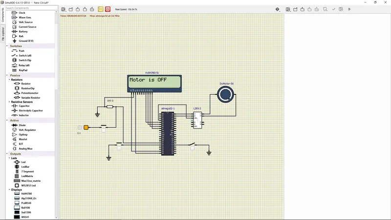
1. MOTOR IS OFF
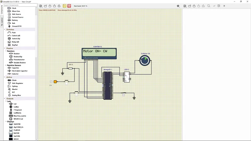
2. MOTOR ON , RUNNING IN CLOCKWISE DIRECTION.
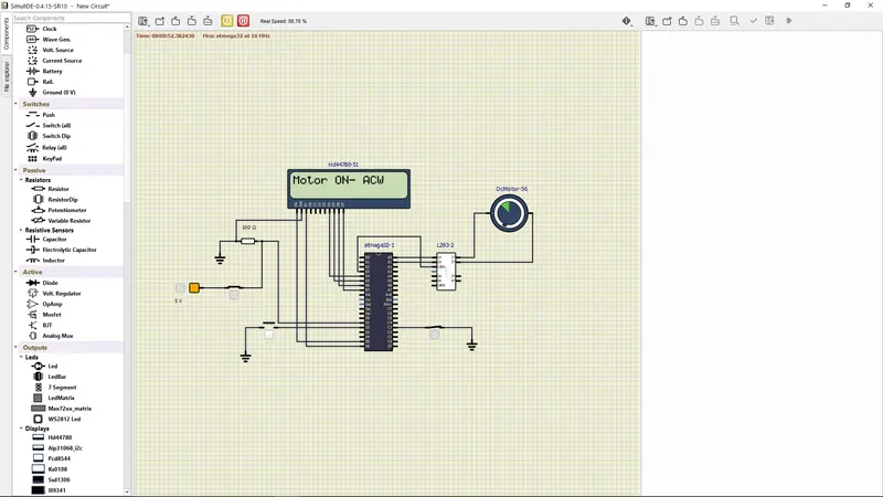
3.MOTOR ON RUNNING IN ANTICLOCKWISE DIRECTION
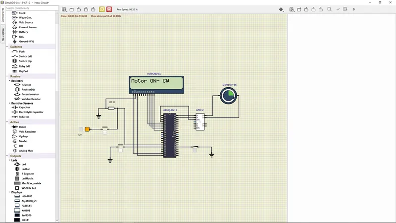
4. MOTOR RUNNING IN 50% AS INTERRUPT PRESSED 2 TIMES INCREMENTED THE SPEED OF THE MOTOR
PROGRAM:
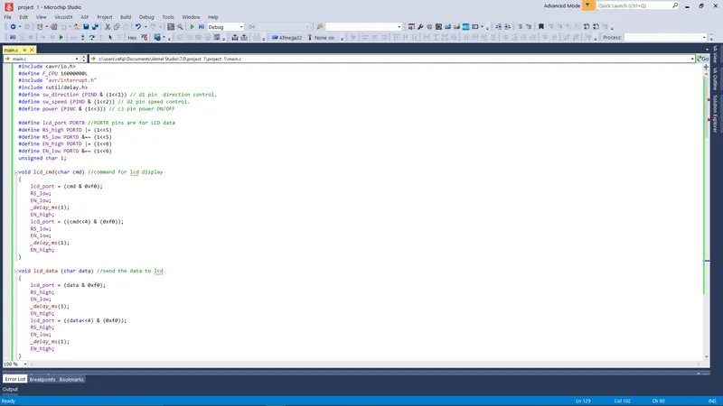
#include <avr/io.h>
#define F_CPU 16000000L
#include "avr/interrupt.h"
#include <util/delay.h>
#define sw_direction (PIND & (1<<1)) // d1 pin direction control.
#define sw_speed (PIND & (1<<2)) // d2 pin speed control.
#define power (PINC & (1<<3)) // c3 pin power ON/OFF
#define lcd_port PORTB //PORTB pins are for LCD data
#define RS_high PORTD |= (1<<5)
#define RS_low PORTD &=~ (1<<5)
#define EN_high PORTD |= (1<<6)
#define EN_low PORTD &=~ (1<<6)
unsigned char i;
void lcd_cmd(char cmd) //command for lcd display
{
lcd_port = (cmd & 0xf0);
RS_low;
EN_low;
_delay_ms(1);
EN_high;
lcd_port = ((cmd<<4) & (0xf0));
RS_low;
EN_low;
_delay_ms(1);
EN_high;
}
void lcd_data (char data) //send the data to lcd
{
lcd_port = (data & 0xf0);
RS_high;
EN_low;
_delay_ms(1);
EN_high;
lcd_port = ((data<<4) & (0xf0));
RS_high;
EN_low;
_delay_ms(1);
EN_high;
}
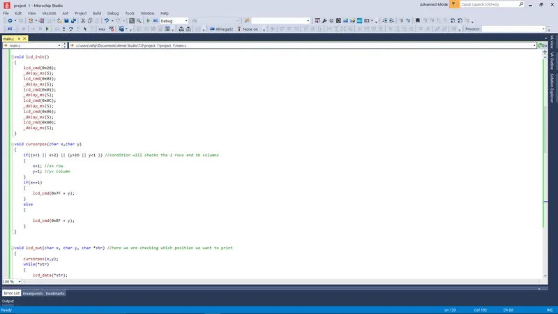
void lcd_init()
{
lcd_cmd(0x28);
_delay_ms(5);
lcd_cmd(0x02);
_delay_ms(5);
lcd_cmd(0x01);
_delay_ms(5);
lcd_cmd(0x0C);
_delay_ms(5);
lcd_cmd(0x06);
_delay_ms(5);
lcd_cmd(0x80);
_delay_ms(5);
}
void cursorpos(char x,char y)
{
if((x<1 || x>2) || (y>16 || y<1 )) //condition will checks the 2 rows and 16 columns
{
x=1; //x= row
y=1; //y= column
}
if(x==1)
{
lcd_cmd(0x7F + y);
}
else
{
lcd_cmd(0xBF + y);
}
}
void lcd_out(char x, char y, char *str) //here we are checking which position we want to print
{
cursorpos(x,y);
while(*str)
{
lcd_data(*str);
str++;
}
}
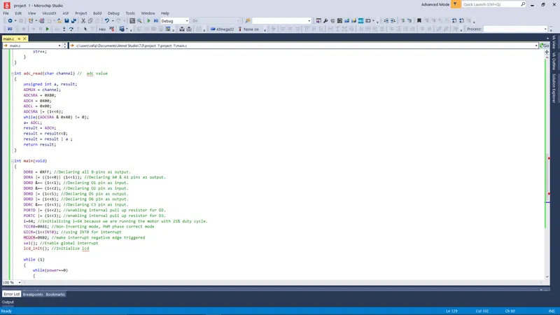
int adc_read(char channel) // adc value
{
unsigned int a, result;
ADMUX = channel;
ADCSRA = 0X80;
ADCH = 0X00;
ADCL = 0x00;
ADCSRA |= (1<<6);
while((ADCSRA & 0x40) != 0);
a= ADCL;
result = ADCH;
result = result<<8;
result = result | a ;
return result;
}
int main(void)
{
DDRB = 0XFF; //Declaring all 8-pins as output.
DDRA |= ((1<<0)| (1<<1)); //Declaring A0 & A1 pins as output.
DDRD &=~ (1<<1); //Declaring D1 pin as input.
DDRD &=~ (1<<2); //Declaring D2 pin as input.
DDRD |= (1<<5); //Declaring D5 pin as output.
DDRD |= (1<<6); //Declaring D6 pin as output.
DDRC &=~ (1<<3); //Declaring C3 pin as input.
PORTD |= (1<<2); //enabling internal pull up resistor for D2.
PORTC |= (1<<3); //enabling internal pull up resistor for D3.
i=64; //initializing i=64 because we are running the motor with 25% duty cycle.
TCCR0=0X61; //Non-Inverting mode, PWM phase correct mode
GICR=(1<<INT0); //using INT0 for interrupt
MCUCR=0X02; //make interrupt negative edge triggered
sei(); //Enable global interrupt
lcd_init(); //Initialize lcd
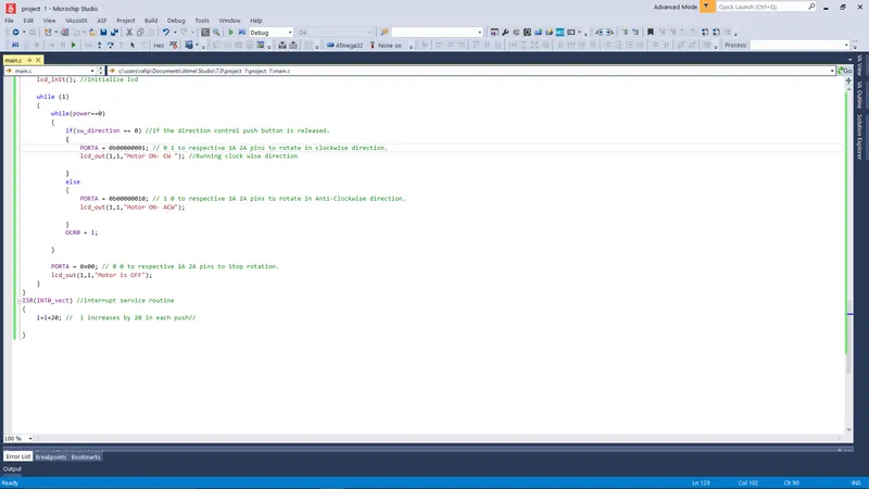
while (1)
{
while(power==0)
{
if(sw_direction == 0) //if the direction control push button is released.
{
PORTA = 0b00000001; // 0 1 to respective 1A 2A pins to rotate in clockwise direction.
lcd_out(1,1,"Motor ON- CW "); //Running clock wise direction
}
else
{
PORTA = 0b00000010; // 1 0 to respective 1A 2A pins to rotate in Anti-Clockwise direction.
lcd_out(1,1,"Motor ON- ACW");
}
OCR0 = i;
}
PORTA = 0x00; // 0 0 to respective 1A 2A pins to Stop rotation.
lcd_out(1,1,"Motor is OFF");
}
}
ISR(INT0_vect) //interrupt service routine
{
i=i+20; // i increases by 20 in each push//
}