Project 1 - Controlling a DC motor using PWM and monitoring its Running status
Live batch 5
Overview of the Project:
Implement a system on the simulator for controlling a DC motor using L293 motor driver, monitor its status and print the running status of motor on the LCD Display.
Goals:
- Implement a system on simulator for Controlling the DC motor using L293 motor driver.
- Displaying the running status of DC motor on the LCD display.
Key Highlights of the Project:
- The DC motor can be controlled by using L293 motor driver.
- The speed of a DC motor can be controlled by varying its input voltage, for doing this is to use PWM (Pulse Width Modulation).
- L293D IC is a typical Motor Driver IC which allows the DC motor to drive on any direction.
Deliverables of this project:
- Implement the system for controlling DC motor.
- Controlling the speed of the DC motor using PMW.
- Displaying the present running status of DC machine on LCD display.
Expected Outcomes:
- Implement a system on simulator to control a DC motor using PMW
- Monitoring the running status of the DC motor using L293 motor driver which allows the DC motor to drive on any direction.
- Running status i.e. on which direction the DC motor is running is to be displayed on the LCD screen.
Soln:
DC Motor : A DC motor is defined as a class of electrical motors that convert direct current electrical energy into mechanical energy. From the above definition, we can conclude that any electric motor that is operated using direct current or DC is called a DC motor.
PWM (Pulse Width Modulation) : Pulse-width modulation, or pulse-duration modulation, is a method of reducing the average power delivered by an electrical signal, by effectively chopping it up into discrete parts. The average value of voltage fed to the load is controlled by turning the switch between supply and load on and off at a fast rate.
L293D IC : The L293D is designed to provide bidirectional drive currents of up to 600-mA at voltages from 4.5 V to 36 V. Both devices are designed to drive inductive loads such as relays, solenoids, DC and bipolar stepping motors, as well as other high-current/high-voltage loads in positive-supply applications.
Program:
#include <avr/io.h>			//Preprocessor for AVR
#define F_CPU 1600000L		//Clock frequency
#include <util/delay.h>		//Delay function
#include "avr/interrupt.h"	//interrupt library for AVR

//define reg selector by setting and clearing the corresponding bit
#define rs_high PORTD |= (1<<0);	//PORT D pin 0 making as high
#define rs_low PORTD &= ~(1<<0);	//PORT D pin 0 making as low

//define enable by setting and clearing the corresponding bit
#define en_high PORTD |= (1<<1);	//PORT D pin 1 making as high
#define en_low PORTD &= ~(1<<1);	//PORT D pin 0 making as low

//define PORTB as the data lines names as lcdport
#define lcdport PORTB		//PORTB as LCDport

void lcd_cmd(unsigned char cmd)		// function definition for lcd command
{
	lcdport =cmd;	//assigning cmd to lcdport
	rs_low;			//calling rs_low
	en_high;		//calling en_high
	_delay_ms(1);	//delay
	en_low;			//calling en_low
}
void lcd_data(unsigned char data)	// function definition for lcd data
{
	lcdport =data;	//assigning data to lcdport
	rs_high;		//calling rs_low
	en_high;		//calling en_high
	_delay_ms(1);	//delay
	en_low;			//calling en_low
}
void lcd_int()		// function definition for lcd initialization
{
	lcd_cmd(0x38);	//2 lines 5x7 matrix
	_delay_ms(5);	//delay of 5ms
	lcd_cmd(0x02);//Return home
	_delay_ms(5);	//delay
	lcd_cmd(0x01);	//Clearing screen
	_delay_ms(5);	//delay of 5ms
	lcd_cmd(0x0c);	//Display on ,cursor off
	_delay_ms(5);	//delay of 5ms
	lcd_cmd(0x06);	//Incrementing cursor
	_delay_ms(5);	//delay of 5ms
	lcd_cmd(0x80);	//Force cursor begin 1st line
	_delay_ms(5);	//delay of 5ms
}
void cursorpos(char x, char y)		// function definition for lcd cursor position
{
	if((x < 1 || x > 2) || (y < 1 || y > 16))	//checking for row and column position
	{
		x=1;	//assigning 1 to x
		y=1;	//assigning 1 to y
	}
	if(x==1)		//to do when the LCD row is equal to 1
	{
		lcd_cmd(0x80+y);	//Cursor force to start from 1st row
	}
	else
	{
		lcd_cmd(0xc0+y);	//Cursor force to start from 2nd row
	}
}
void lcd_out(char a, char b, char *str)	//create a function definition for  accessing/print the string on LCD
{
	cursorpos(a,b);		//calling the cursor position function
	while(*str)
	{
		lcd_data(*str);		//passing the string as parameter
		str++;				//increment str
	}
}

int a;		//global variable declaration

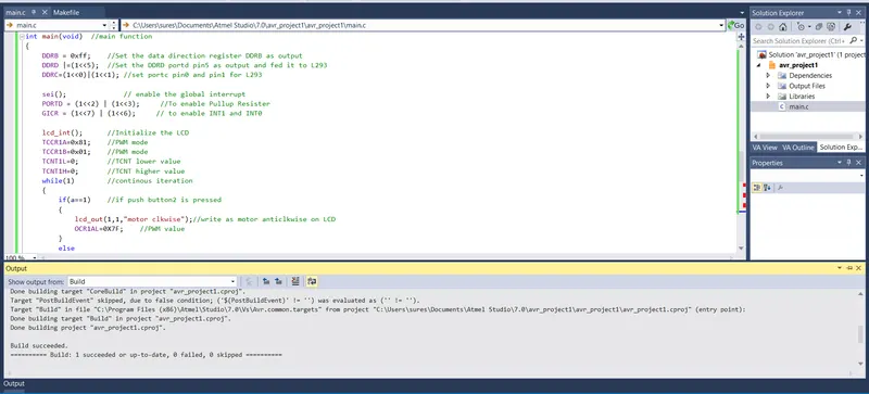
int main(void)	//main function
{
	DDRB = 0xff;	//Set the data direction register DDRB as output
	DDRD |=(1<<5);	//Set the DDRD portd pin5 as output and fed it to L293
	DDRC=(1<<0)|(1<<1);	//set portc pin0 and pin1 for L293

	sei();				// enable the global interrupt
	PORTD = (1<<2) | (1<<3);	 //To enable Pullup Resister
	GICR = (1<<7) | (1<<6);		// to enable INT1 and INT0

	lcd_int();		//Initialize the LCD
	TCCR1A=0x81;	//PWM mode
	TCCR1B=0x01;	//PWM mode
	TCNT1L=0;		//TCNT lower value
	TCNT1H=0;		//TCNT higher value
	while(1)		//continous iteration
	{
		if(a==1)	//if push button2 is pressed
		{
			lcd_out(1,1,"motor clkwise");//write as motor anticlkwise on LCD
			OCR1AL=0X7F;	//PWM value
		}
		else
		{
			OCR1AL=0X3F;	//PWM value
			lcd_out(1,1,"motor anti-clkwise");	//write as motor clkwise on LCD
		}

	}
}
ISR(INT0_vect)		//when the push button at PD1 pressed
{
	PORTC |= (1<<1);	//setting portc pin1 for running motor in forward
	PORTC &= ~(1<<0);	//clearing portc pin0 for running motor in forward
	a=1;				//assign a as 1
	lcd_cmd(0x01);		//caller function
	_delay_ms(5);	//delay
}
ISR(INT1_vect)	//when the push button at PD2 pressed
{
	PORTC |= (1<<0);	//setting portc pin0 for running motor in reverse
	PORTC &= ~(1<<1);	//clearing portc pin1 for running motor in reverse
	a=2;				//assign a as 2
	lcd_cmd(0x01);		//caller function
	_delay_ms(5);		//delay
}
Output:
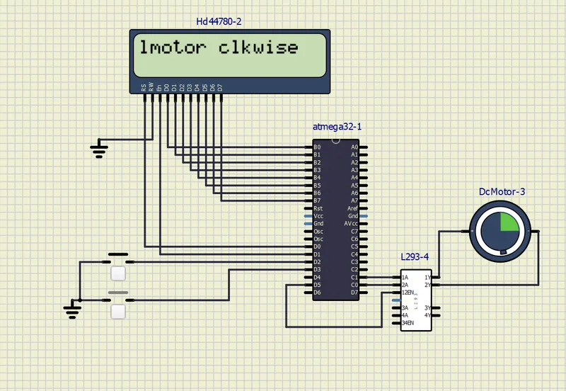
Motor in clock wise (forward):
Motor in anti-clock wise (Reverse):
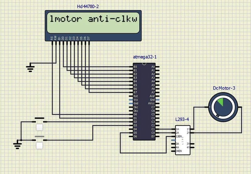
Conclusion : Sucessfully implement a system on simulator to control a DC motor using PMW using L293 motor driver which allows the DC motor to drive on any direction and displayed on the LCD screen.