Project 1 - Controlling a DC motor using PWM and monitoring its Running status
Project #1
Aim:
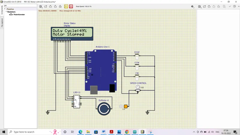
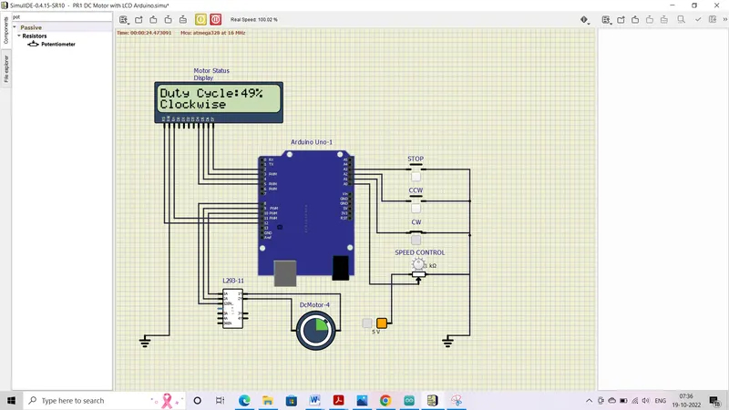
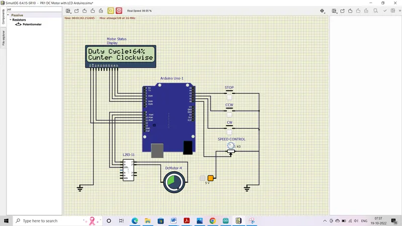
To implement a simulation for Control a DC motor using PWM with L293 and monitoring its Running status by using LCD.
16x2 LCD
Introduction for LCD interfacing with Atmega32
LCDs (Liquid Crystal Displays) are used for displaying status or parameters in embedded systems.
LCD 16x2 is a 16 pin device which has 8 data pins (D0-D7) and 3 control pins (RS, RW, EN). The remaining 5 pins are for supply and backlight for the LCD.
The control pins help us configure the LCD in command mode or data mode. They also help configure read mode or write mode and also when to read or write.
LCD 16x2 can be used in 4-bit mode or 8-bit mode depending on the requirement of the application. In order to use it, we need to send certain commands to the LCD in command mode and once the LCD is configured according to our need, we can send the required data in data mode.
4 Bit Mode
- In 4-bit mode, data/command is sent in a 4-bit (nibble) format.
- To do this 1st send a Higher 4-bit and then send a lower 4-bit of data/command.
- Only 4 data (D4 - D7) pins of 16x2 of LCD are connected to the microcontroller and other control pins RS (Register select), RW (Read/write), E (Enable) is connected to other GPIO Pins of the controller.
Therefore, due to such connections, we can save four GPIO pins which can be used for another application.
Initialization
- Wait for 15ms, Power-on initialization time for LCD16x2
- Send 0x02 command which initializes LCD 16x2 in 4-bit mode
- Send 0x28 command which configures LCD in 2-line, 4-bit mode, and 5x8 dots
- Send any Display ON command (0x0E, 0x0C)
- Send 0x06 command (increment cursor)
Command write function
- First, send a Higher nibble of command
- Make RS pin low, RS=0 (command reg)
- Make RW pin low, RW=0 (write operation) or connect it to ground
- Give High to Low pulse at Enable (E)
- Send lower nibble of command
- Give High to Low pulse at Enable (E)
Data write function
- First, send a Higher nibble of data
- Make RS pin high, RS=1 (data reg)
- Make RW pin low, RW=0 (write operation) or connect it to ground
- Give High to Low pulse at Enable (E)
- Send lower nibble of data
- Give High to Low pulse at Enable (E)
BASIC COMMANDS USED IN LCD DISPLAY
|
COMMANDS |
DESCRIPTION |
|
0x01 |
Clear screen |
|
0x02 |
return home |
|
0x04 |
Cursor decrement |
|
0x05 |
Display shifts to right |
|
0x06 |
Cursor increment |
|
0x07 |
Display shifts to left |
|
0x08 |
Cursor and display OFF |
|
0x10 |
Cursor position Shifts to left |
|
0x14 |
Cursor position shifts to right |
|
0x38 |
Using two lines, 8-bit mode |
|
0x28 |
Using two lines, 4-bit mode |
|
0x80 |
Move cursor to the beginning of first line |
|
0x0C |
Display ON, cursor OFF |
|
0XC0 |
Move cursor to the beginning of second line |
|
0x0A |
Display OFF, cursor ON |
|
0x0E |
Display ON, cursor blinking |
|
0x30 |
For display in one line in 8-bit mode |
|
0x20 |
For display in one line in 4-bit mode |
|
0x0F |
Display data on cursor blinking |
|
0x18 |
Shift complete data to left side |
|
0x1C |
Shift complete data to right side |
L293D DC Motor Driver
PIN Diagram
Power Consumption
L293DTotal number of pins = 16 |
L293Total number of pins = 28 |
Pin Output Logic
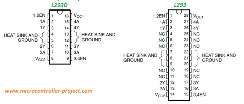
1,2EN: To activate the channel 1 we supply +5v to this pin.
3,4EN: To activate the channel 2 we supply +5v to this pin.
Vcc1: Input voltage to derive the internal circuit (darligton array) = 4.5 to 5 v
Vcc2: Supply/Output to appear at output = 4.5 to 36 v
1A: Channel-1 Input Pin
2A: Channel-1 Input Pin
1Y: Channel-1 Output Pin
2Y: Channel-1 Output Pin
3A: Channel-2 Input Pin
4A: Channel-2 Input Pin
3Y: Channel-2 Output Pin
4Y: Channel-2 Output Pin
1A and 2A are control pins of channel 1. 1Y and 2Y are output pins of channel 1. Similarly 3A and 4A are input pins for channel 2 and 3Y, 4Y are output pins for channel 2. 1,2En are enable pins of channel 1. 3,4 EN are enable pins of channel 2. Individual l293d motor driver channel equivalent circuit is given below.
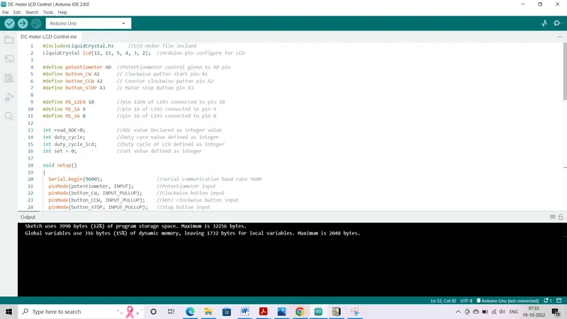
Program for DC Motor Control and Status Display by Arduino IDE
#include<LiquidCrystal.h> //LCD Heder file inclued
LiquidCrystal lcd(12, 11, 5, 4, 3, 2); //Arduino pin configure for LCD
#define potentiometer A0 //Potentionmeter control given to A0 pin
#define button_CW A1 // Clockwise putton start pin A1
#define button_CCW A2 // Counter clockwise putton pin A2
#define button_STOP A3 // Motor stop Button pin A3
#define M1_12EN 10 //pin 12EN of L293 connected to pin 10
#define M1_1A 9 //pin 1A of L293 connected to pin 9
#define M1_2A 8 //pin 2A of L293 connected to pin 8
int read_ADC=0; //ADC value Declared as integer value
int duty_cycle; //Duty cyce value defined as integer
int duty_cycle_lcd; //Duty cycle of LCD defined as integer
int set = 0; //set value defined as integer
void setup()
{
Serial.begin(9600); //serial communication baud rate 9600
pinMode(potentiometer, INPUT); //Potentiometer input
pinMode(button_CW, INPUT_PULLUP); //Clockwise button input
pinMode(button_CCW, INPUT_PULLUP); //Anti clockwise button input
pinMode(button_STOP, INPUT_PULLUP); //Stop button input
pinMode(M1_12EN, OUTPUT); //L293 12EN input
pinMode(M1_1A, OUTPUT); //L293 1A input
pinMode(M1_2A, OUTPUT); //L293 2A input
lcd.begin(16,2); //16x2 LCD eneble
lcd.setCursor(0,1); //Set cursor on (0,1) place
lcd.print("Hello"); //Initialize LCD
delay(500); //Delay 500ms
lcd.clear(); //clear LCD
}
voidloop()
{
read_ADC = analogRead(potentiometer); //Read potentiometer value analog
duty_cycle = map(read_ADC, 0, 1023, 0,255); //Duty cycle display
duty_cycle_lcd = map(read_ADC, 0, 1023,0, 100);//Duty cycle display
analogWrite(M1_12EN, duty_cycle); //Writ the duty cycle
lcd.setCursor(0,0); //Set LCD cursor 0,0
lcd.print("Duty Cycle:"); //Print "Duty cycle"
lcd.print(duty_cycle_lcd); //Print duty cycl value
lcd.print("% "); //Print %
if(digitalRead (button_CW) == 0)(set = 1); //Read Button value for CW
if(digitalRead (button_CCW) == 0)(set = 2); //Read Button value for CCW
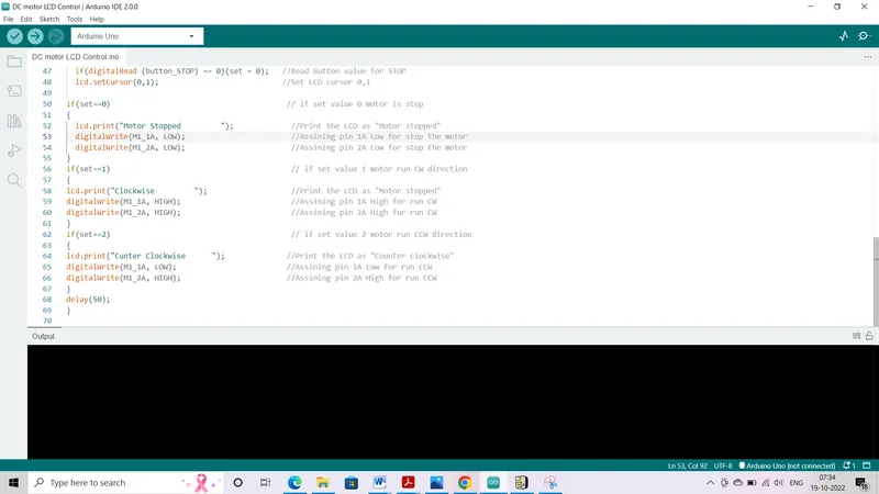
if(digitalRead (button_STOP) == 0)(set = 0); //Read Button value for STOP
lcd.setCursor(0,1); //Set LCD cursor 0,1
if(set==0) // if set value 0 motor is stop
{
lcd.print("Motor Stopped "); //Print the LCD as "Motor stopped"
digitalWrite(M1_1A, LOW); //Assining pin 1A Low for stop the motor
digitalWrite(M1_2A, LOW); //Assining pin 2A Low for stop the motor
}
if(set==1) // if set value 1 motor run CW direction
{
lcd.print("Clockwise "); //Print the LCD as "Motor stopped"
digitalWrite(M1_1A, HIGH); //Assining pin 1A High for run CW
digitalWrite(M1_2A, HIGH); //Assining pin 2A High for run CW
}
if(set==2) // if set value 2 motor run CCW direction
{
lcd.print("Cunter Clockwise "); //Print the LCD as "Counter clockwise"
digitalWrite(M1_1A, LOW); //Assining pin 1A Low for run CCW
digitalWrite(M1_2A, HIGH); //Assining pin 2A High for run CCW
}
delay(50);
}