Project 1 - Controlling a DC motor using PWM and monitoring its Running status
- a system on simulator for Controlling the DC motor using L293 motor driver.
The code for the program is as follows:
#include <avr/io.h>
#define F_CPU 16000000L
#include <util/delay.h>

#define rs_high() PORTD |=(1<<0);//PD0
#define rs_low() PORTD &= ~(1<<0);

#define en_high() PORTD |= (1<<2);//PD2
#define en_low() PORTD &= ~(1<<2);

#define lcdport PORTB

void lcd_command(unsigned char cmd);//function declaration for passing lcd commands

void lcd_data(unsigned char data);//function declaration for lcd_data

void lcd_init(); //function declaration for initialization of lcd

void cursorpos(char x, char y);//function declaration for cursor position


void lcd_out(char x, char y, char *str);//function declaration for output obtained for LED


int main(void) //definition of main function
{

	//unsigned int volt=87;
	DDRA=0XFF; //Declare port A as OUTPUT PORT
	lcd_init();//initialize the LED using sub_function lcd_init


	while(1)//infinite while loop
	{

		PORTA = 0x05; //00000001
		lcd_out(1,1,"M1 CW          ");//Print the  statement M1 CW on first row first column
		lcd_out(2,1,"M2 CW          ");//Print the statement M2 CW on second row first column
		_delay_ms(4000);//wait for 4 seconds


		PORTA = 0x0A; //00000000
		lcd_out(1,1,"M1AntiClockWise");//print the statement "M1Anticlockwise on 1st row, 1st column of LCD display//
		lcd_out(2,1,"M2AntiClockWise");//print the statement "M2Anticlockwise on 2nd row, 1st column of LCD sisplay//
		_delay_ms(4000); //wait for 4 seconds

		PORTA = 0x09; //00000000
		lcd_out(1,1,"M1 ClockWise    ");//print the statement "M1 Clockwise on LCD display
		lcd_out(2,1,"M2AntiClockWise");//print the statement "M2 Anticlockwise on LCD display
		_delay_ms(4000);//wait for 4 seconds

		PORTA = 0x00; //00000000
		lcd_out(1,1,"M1 Stop        ");// Print the statement "M1 Stop "  on first row 1st column of LCD
		lcd_out(2,1,"M2 Stop        ");//Print the statement "M2 Stop " on second row second column of LCD
		_delay_ms(4000); //wait for 4 seconds
	}

}

void lcd_command(unsigned char cmd)
{

	lcdport = cmd;//cmd is a variable of unsigned char datatype
	rs_low();//rs_low function is called
	en_high();//enable high function is called
	_delay_ms(1);//wait for 1 ms
	en_low();//call the pre-defined fuction en_low
}

void lcd_data(unsigned char data)
{

	lcdport = data;
	rs_high();//register select high pin is enabled
	en_high();//enable high function is called
	_delay_ms(1);//wait for 1ms
	en_low();//enable low function is called
}

void lcd_init()
{

	lcd_command(0x38);_delay_ms(5);
	lcd_command(0x01);_delay_ms(5);
	lcd_command(0x0c);_delay_ms(5);
	lcd_command(0x06);_delay_ms(5);


}

void cursorpos(char x, char y)
{

	if( (x < 1 || x > 2) || (y < 1 || y > 16) )
	{
		x = 1;
		y = 1;
	}
	if(x == 1)
	lcd_command(0x80+y);
	else
	lcd_command(0xC0+y);

}


void lcd_out(char x,char y,char *str)
{

	cursorpos(x,y);
	while(*str) //string pointer is included in while loop
	{
		lcd_data(*str);
		str++;
	}
}
There are some preprocessor directives for associating the pre-defined functions with PORT A,B,C,D like follows:
#define rs_high() PORTD |=(1<<0);//PD0
#define rs_low() PORTD &= ~(1<<0);

#define en_high() PORTD |= (1<<2);//PD2
#define en_low() PORTD &= ~(1<<2);

#define lcdport PORTB
The sub-functions are defined for executing each action on the LCD:
void lcd_command(unsigned char cmd);//function declaration for passing lcd commands

void lcd_data(unsigned char data);//function declaration for lcd_data

void lcd_init(); //function declaration for initialization of lcd

void cursorpos(char x, char y);//function declaration for cursor position


void lcd_out(char x, char y, char *str);//function declaration for output obtained for LED
The main function has all the function calls for performing the desired output which is printing the status of the motor on the LCD.
int main(void) //definition of main function
{

	//unsigned int volt=87;
	DDRA=0XFF; //Declare port A as OUTPUT PORT
	lcd_init();//initialize the LED using sub_function lcd_init


	while(1)//infinite while loop
	{

		PORTA = 0x05; //00000001
		lcd_out(1,1,"M1 CW          ");//Print the  statement M1 CW on first row first column
		lcd_out(2,1,"M2 CW          ");//Print the statement M2 CW on second row first column
		_delay_ms(4000);//wait for 4 seconds


		PORTA = 0x0A; //00000000
		lcd_out(1,1,"M1AntiClockWise");//print the statement "M1Anticlockwise on 1st row, 1st column of LCD display//
		lcd_out(2,1,"M2AntiClockWise");//print the statement "M2Anticlockwise on 2nd row, 1st column of LCD sisplay//
		_delay_ms(4000); //wait for 4 seconds

		PORTA = 0x09; //00000000
		lcd_out(1,1,"M1 ClockWise    ");//print the statement "M1 Clockwise on LCD display
		lcd_out(2,1,"M2AntiClockWise");//print the statement "M2 Anticlockwise on LCD display
		_delay_ms(4000);//wait for 4 seconds

		PORTA = 0x00; //00000000
		lcd_out(1,1,"M1 Stop        ");// Print the statement "M1 Stop "  on first row 1st column of LCD
		lcd_out(2,1,"M2 Stop        ");//Print the statement "M2 Stop " on second row second column of LCD
		_delay_ms(4000); //wait for 4 seconds
	}

}
The sub function lcd_command is used for passing the predefined commands to the LCD:
void lcd_command(unsigned char cmd)
{

	lcdport = cmd;//cmd is a variable of unsigned char datatype
	rs_low();//rs_low function is called
	en_high();//enable high function is called
	_delay_ms(1);//wait for 1 ms
	en_low();//call the pre-defined fuction en_low
}
The sub-function lcd_data is used for passing the data to the LCD. Which is the statements in this case.
void lcd_data(unsigned char data)
{

	lcdport = data;
	rs_high();//register select high pin is enabled
	en_high();//enable high function is called
	_delay_ms(1);//wait for 1ms
	en_low();//enable low function is called
}
The sub-function lcd_init is used to initialise the LCD display
void lcd_init()
{

	lcd_command(0x38);_delay_ms(5);
	lcd_command(0x01);_delay_ms(5);
	lcd_command(0x0c);_delay_ms(5);
	lcd_command(0x06);_delay_ms(5);


}
The sub-function cursorpos is used to define the cursor position of the LCD and to specify the row number and column number
void cursorpos(char x, char y)
{

	if( (x < 1 || x > 2) || (y < 1 || y > 16) )
	{
		x = 1;
		y = 1;
	}
	if(x == 1)
	lcd_command(0x80+y);
	else
	lcd_command(0xC0+y);

}
Finally the output is taken through the lcd_out sub-function:
void lcd_out(char x,char y,char *str)
{

	cursorpos(x,y);
	while(*str) //string pointer is included in while loop
	{
		lcd_data(*str);
		str++;
	}
}
The circuit looks as shown below:
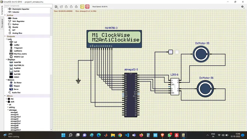
As per the program the LCD is operating in 8-bit mode. Port D is used as Output port, PORT A is used as an input as well as an output port. Here the input for the LCD is the output condition of the motor running whether clockwise or anticlockwise. A motor driver LM-293 is connected On port pin PA0,PA1, PA2,PA3. A fixed 5V supply is given to 34EN pin of the LM293 IC. The Motor M1 and M2 are connected to output pins of motor driver.
As the commands are given in the program each delay is provided for three steps and the statements are printed on the LCD screen.
Hence the monitoring system for DC motor using bare metal programming is implemented successfully.