Project 1_Comparative study of different storey buildings for Seismic forces
1Q]
AIM: -
Factors influencing the Natural Period of a building
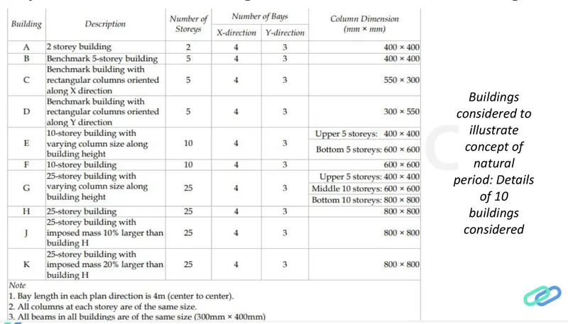
- Effect of stiffness on T: Compare fundamental natural periods of buildings E & F as well as G & H. Why is there a marginal or significant difference in the fundamental natural periods?
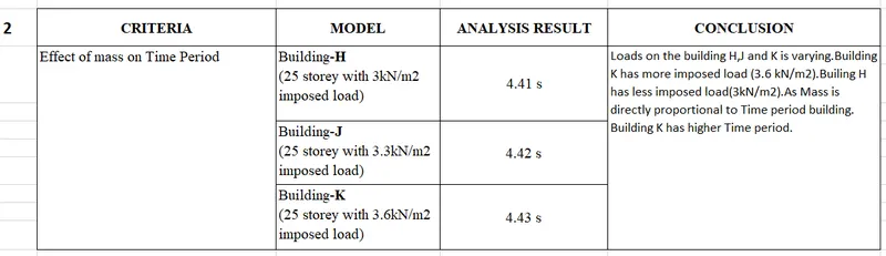
- Effect of mass on T: Compare fundamental natural periods of buildings H, J and K.Have the buildings become more flexible or stiff due to change in mass?
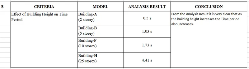
- Effect of Building Height on T: How does the fundamental natural periods of Buildings A, B, F and H change with change in building height?
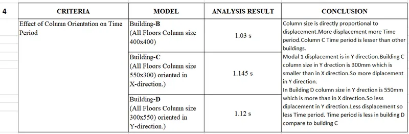
- Effect of Column Orientation on T: How does the fundamental natural periods of Buildings B, C and D change with change in column orientation?
Factors influencing the Mode shape of oscillations
- Effect of Flexural Stiffness of Structural Elements on mode shapes: Compare fundamental mode shape of Building B in two situations when flexural stiffness of beams relative to that of adjoining columns is very small versus when it is large.
- Effect of Axial Stiffness of Vertical Members on mode shapes: Compare fundamental mode shape of Building H in two situations when axial cross-sectional area of columns is very small versus when it is large.
- Effect of Degree of Fixity at column bases on mode shape: Compare fundamental mode shape of Building B in two situations when base of columns is pinned versus when it is fixed.
PROCEDURE: -
MODEL-A
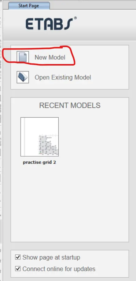
Open ETABS software.
Click on New
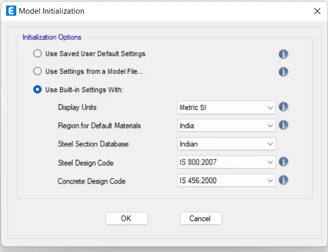
Model Initialization dialogue box opens
Select Use Built-in Settings with:
Display units: Metric SI
Region for Default materials: India
Steel Connection Database: Indian
Steel Design Code: IS 800: 2007
Concrete Design Code: IS 456:2000
Set these changes in the Model Initialization
After setting above changes Click OK
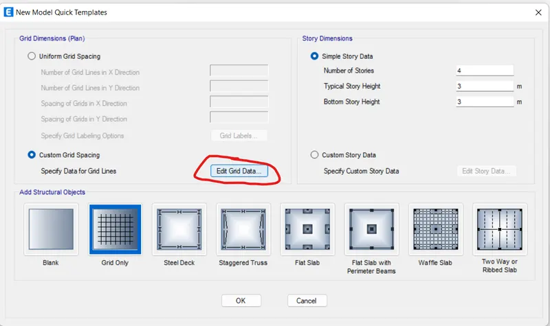
Now, New Model Quick Template dialogue box opens
Select Custom Grid Spacing
Click on Edit Grid Data
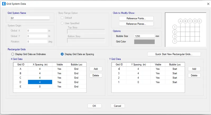
Grid System Data dialogue box opens
Under Rectangular Grids, Select Display grid Data as Spacing
Under X Grid Data column enter the data as per given data
Under Y Grid Data column enter the data as per given data
After entering the Grid Data press OK
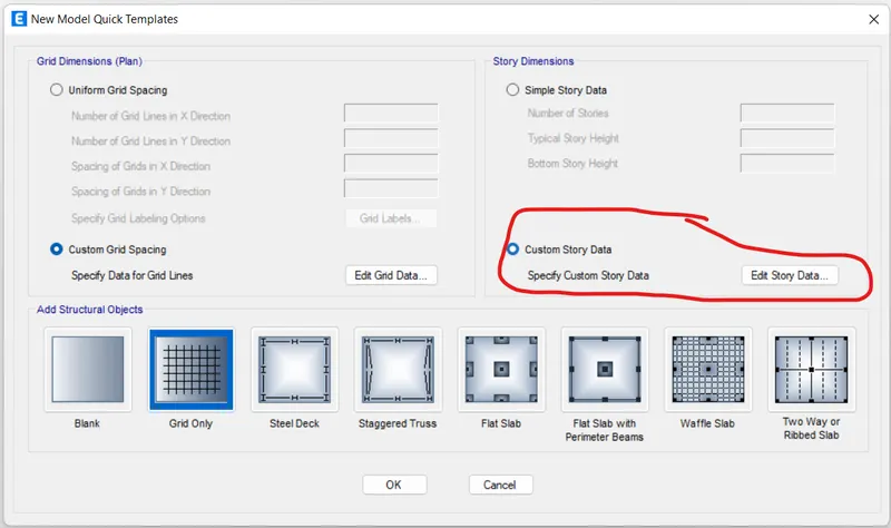
Select Custom Story Data in New Model Quick Template dialogue box
Click on Edit Story Data
Story Data dialogue box opens
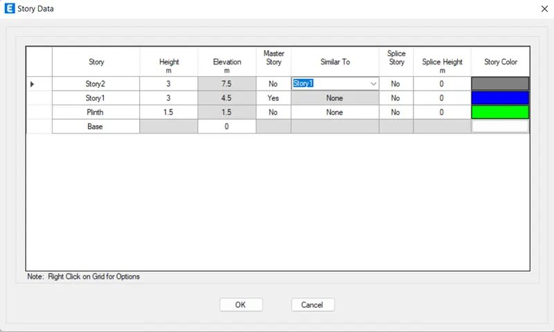
Edit the default storeys
Add Plinth in Story column and Height 1.5m in Height column.
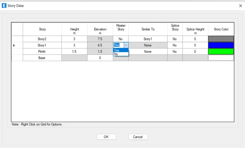
Select YES for the Story1 in Master Story column.
Select Story1 for the rest of the storeys in Similar To column
Model appears on the screen
Click on the Define Tab
Select Material Properties
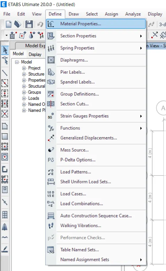
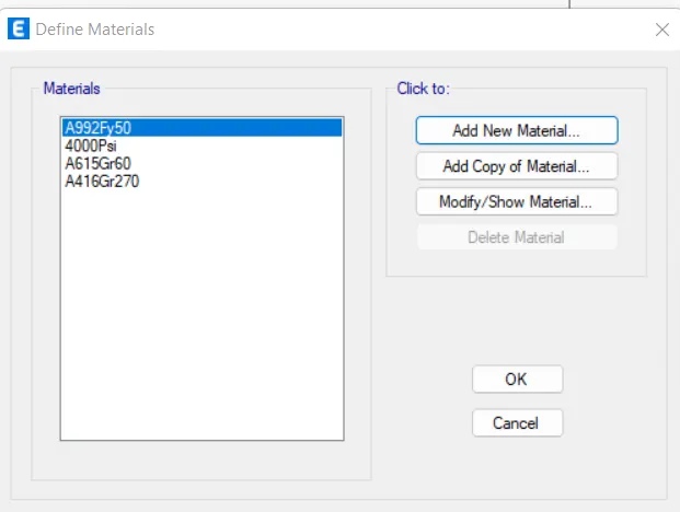
Define Materials dialogue box opens
Click on Add New Material
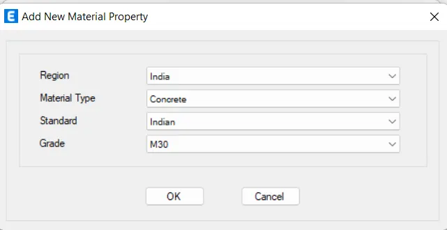
Add New Material Property dialogue box opens
Region: India
Material Type: Concrete
Standard: Indian
Grade: M30
After entering the data, press OK
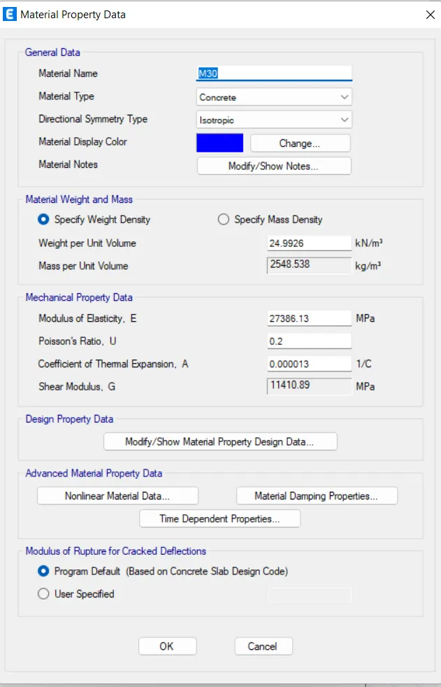
Material Property Data dialogue box opens
Press OK
Click on Add New Material
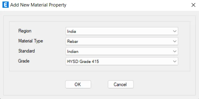
Add New Material Property dialogue box opens
Region: India
Material Type: Rebar
Standard: Indian
Grade: HYSD Grade 415
After entering the data, press OK
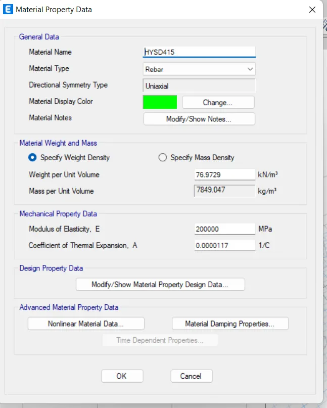
Material Property Data dialogue box opens
Press OK
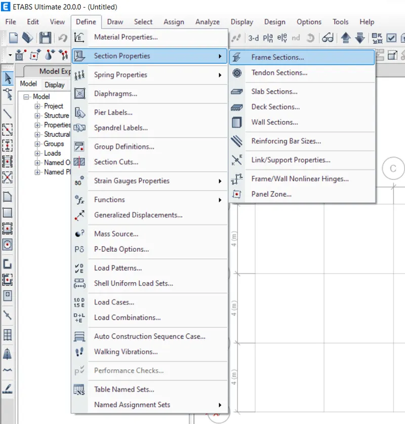
Click on the Define Tab
Click on Section Properties and select Frame Sections
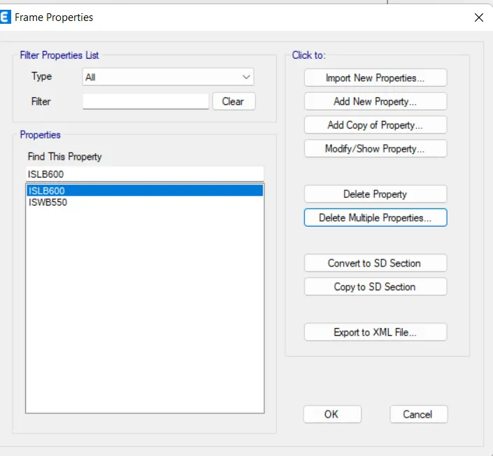
Frame Properties dialogue box opens
Click on Add New Property
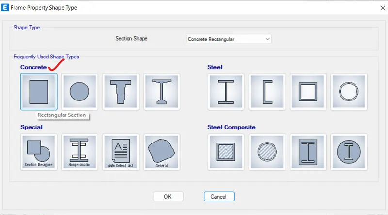
Frame Property Shape Type dialogue box opens
Section Shape: Concrete Rectangular
Click on Rectangle shape under Concrete
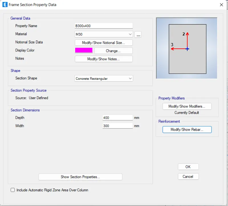
Frame Section Property data dialogue box opens
Enter the data
General Data
Propert Name: Beam 300x400
Material: M30
Section dimensions
Width: 300mm
Depth: 400mm
Click on Modify/Show Rebar option under Reinforcement
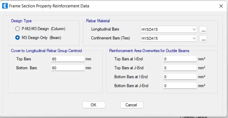
Frame Section Property Reinforcement data dialogue box opens
Design Type: M3 Design only(beams)
Rebar Material: HYSD415
Press Ok
Click on the Define Tab
Click on Section Properties and select Frame Sections
Frame Properties dialogue box opens
Click on Add New Property
Frame Property Shape Type dialogue box opens
Section Shape: Concrete Rectangular
Click on Rectangle shape under Concrete
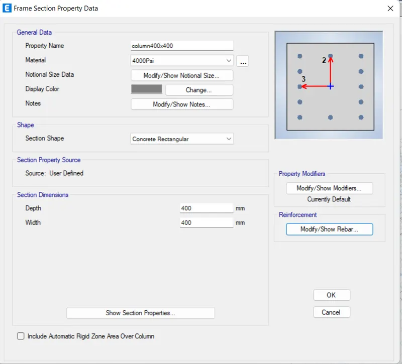
Frame Section Property data dialogue box opens
Enter the data
General Data
Propert Name: Column400x400
Material: M30
Section dimensions
Width: 400mm
Depth: 400mm
Click on Modify/Show Rebar option under Reinforcement
Frame Section Property Reinforcement data dialogue box opens
Design Type: P-M2-M3 Design(columns)
Rebar Material: HYSD415
Press Ok
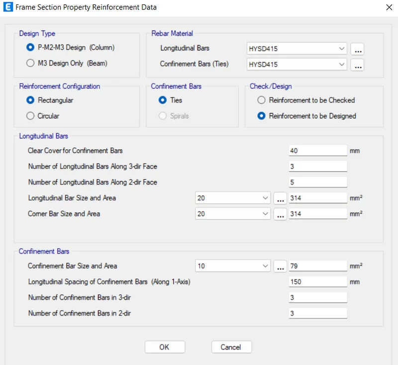
We can see the new created Frame properties in the properties table
Click on the Define Tab
Click on Section Properties and select Slab Sections
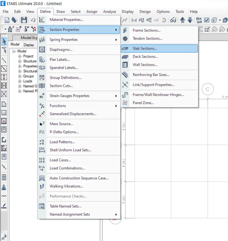
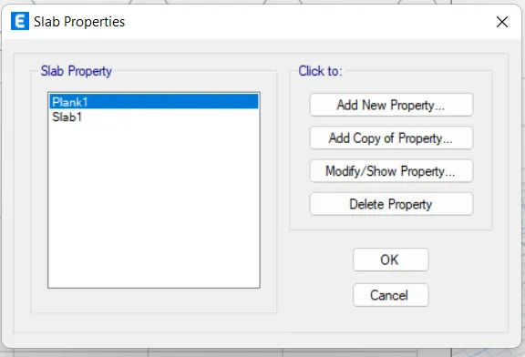
Slab Properties dialogue box opens
Click on Add New Property
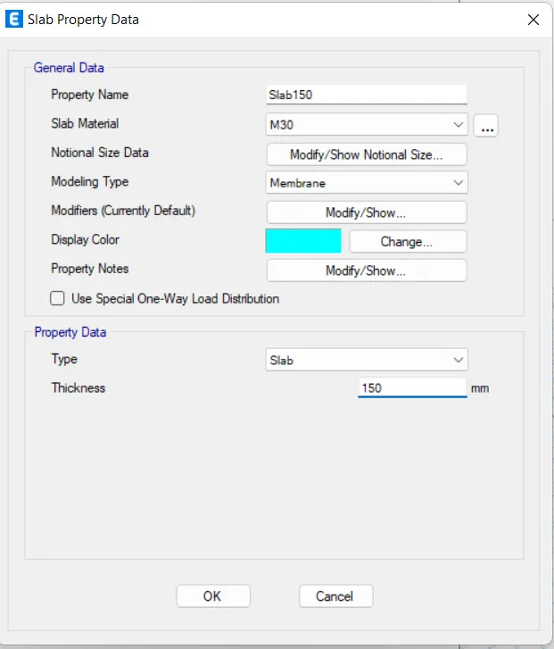
Slab Property Data dialogue box opens
General Data
Propert Name: Slab150mm
Modeling Type: membrane
Thickness: 150mm
Press Ok
Click on the Define Tab
Select Load patterns
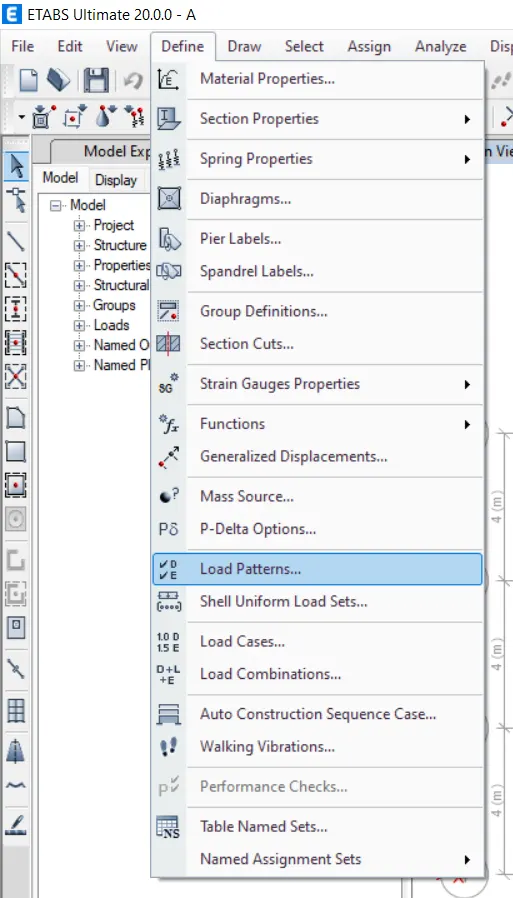
Define Load patterns dialogue box opens
Click on Add New Load option
Wall load under super dead Type
Live load under Live Type
EQX load under Seismic Type
EQY load under Seismic Type
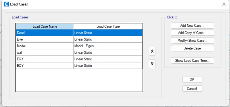
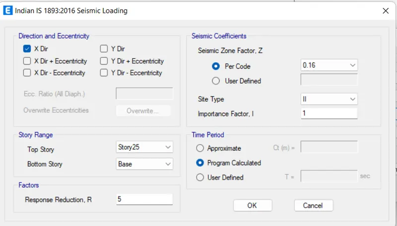
Select EQX load and click on modify lateral load option
Indian IS 1893:2016 Seismic loading dialogue box opens
Direction and Eccentricity: X dir
Seismic Co-eff: 0.16 (zone 3)
Site Type: 2
Press OK
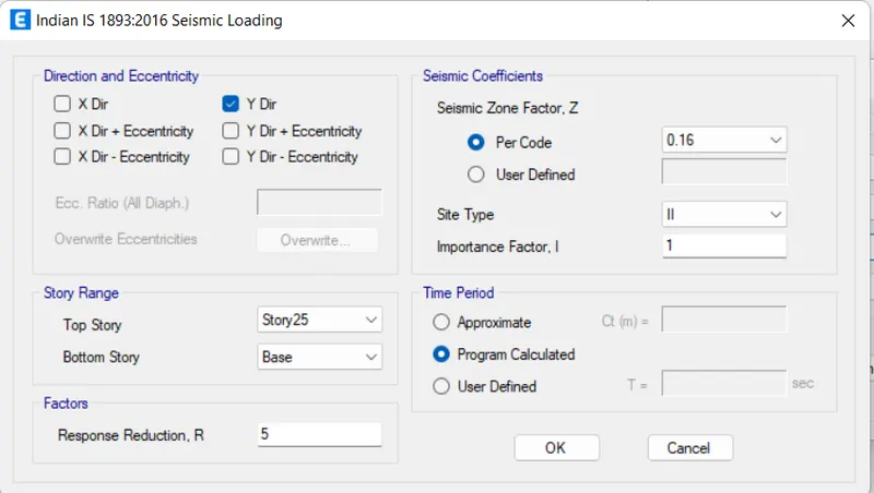
Select EQY load and click on modify lateral load option
Indian IS 1893:2016 Seismic loading dialogue box opens
Direction and Eccentricity: Y dir
Seismic Co-eff: 0.16 (zone 3)
Site Type: 2
Press OK
Click on the Define Tab
Select Mass Source
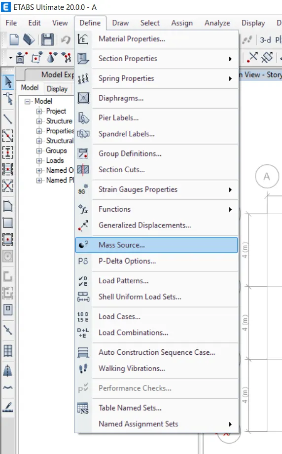
Mass Source dialogue box opens
Click on modify/show Mass Source
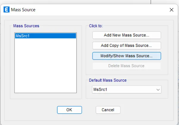
Mass Source Data dialogue box opens
Load Pattern Multiplier
Dead 1
Live 0.25
Wall 1
Mass Source: Specified load patterns
Press Ok
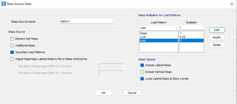
Click on the Define Tab
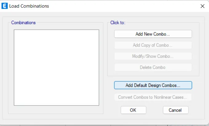
Select Load Combinations
Load Combinations dialogue box opens
Click on Add Default Design Combos
Add Default Design Combos dialogue box opens
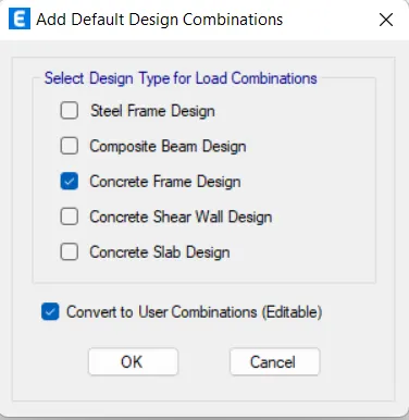
Select Concrete Frame Design option from the available list.
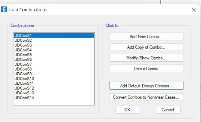
Press OK
Combination list appears in the column.
Now, we have to create beams, columns, and slabs.
Select Quick Draw Column tool from the Draw panel
Under property browser
Property: Column 400x400
Apply the changes to All Stories
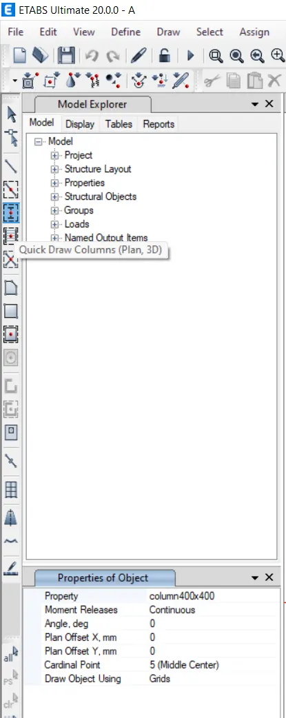
Click on the nodes of the Grids. - A1, A2, A3, A4
We placed 4 columns at the nodes.
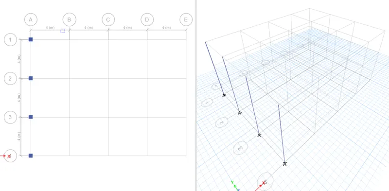
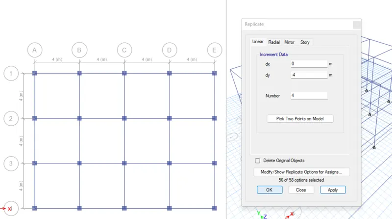
Click on the Edit Tab
Select Replicate
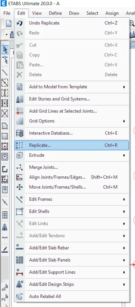
Replicate dialogue box opens
dx = 4
number = 4
Click on Apply and press OK
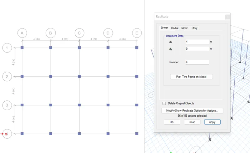
We placed columns at all grid points.
Select Quick Draw Beam/Column tool from the Draw panel
Under property browser
Property: Beam 300x400
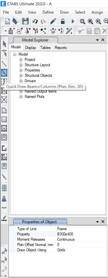
Click on all the Grids lines.
We placed beams at all grid lines.
Select Quick Draw Floor/wall tool from the Draw panel
Under property browser
Property: Slab150mm
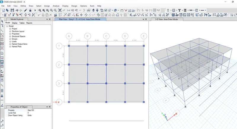
Select all the planes of the Grids
We placed slabs.
We have to apply Load on the Structure.
Click on SelectTab
Click on Select
Go to Properties from the list
Select Frame Sections
Select beam300x400 from the list
All the beams are selected

Click on Assign Tab
Click on Frame Loads
Select Distributed option.
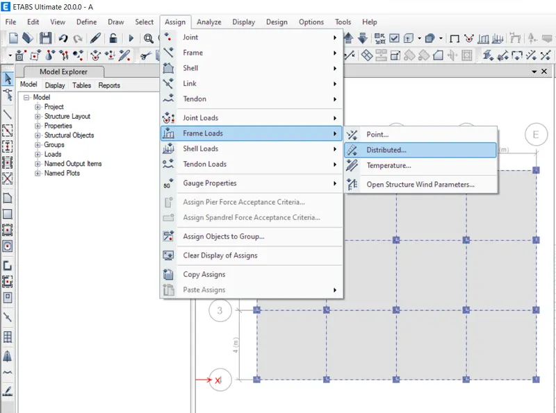
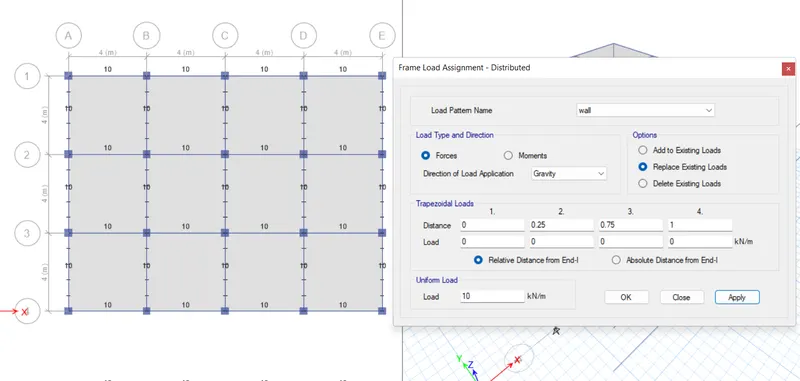
Frame load Assignment-Distributed dialogue box opens
Load: 10 Kn/m
Click Apply and Press OK
Click on SelectTab
Click on Select
Go to Properties from the list
Select Slab Sections
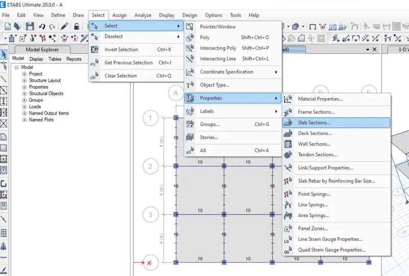
Select slab150mm from the list
All the slabs are selected
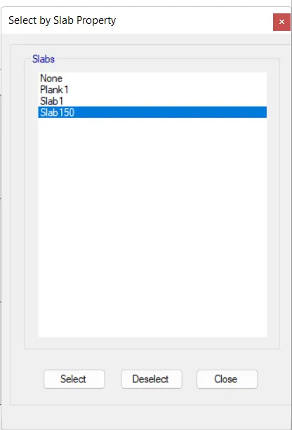
Click on Assign Tab
Click on shell Loads
Select Uniform option.
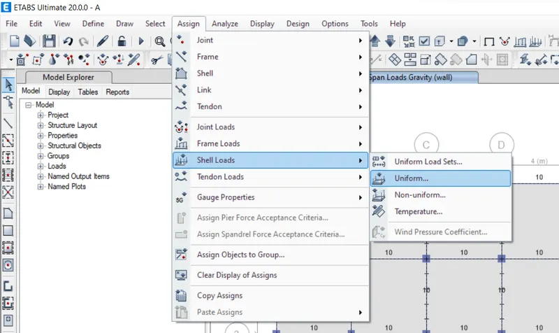
Shell load Assignment-Uniform dialogue box opens
Load Pattern: live load
Load: 3 Kn/m
Click Apply and Press OK
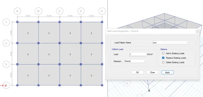
Click on Assign Tab
Click on shell tool
Select Diaphragms.
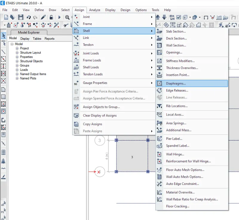
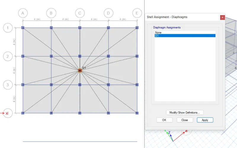
Shell Assignment- Diaphragms dialogue box opens
Select D1 in the list
Click on Apply and Press OK
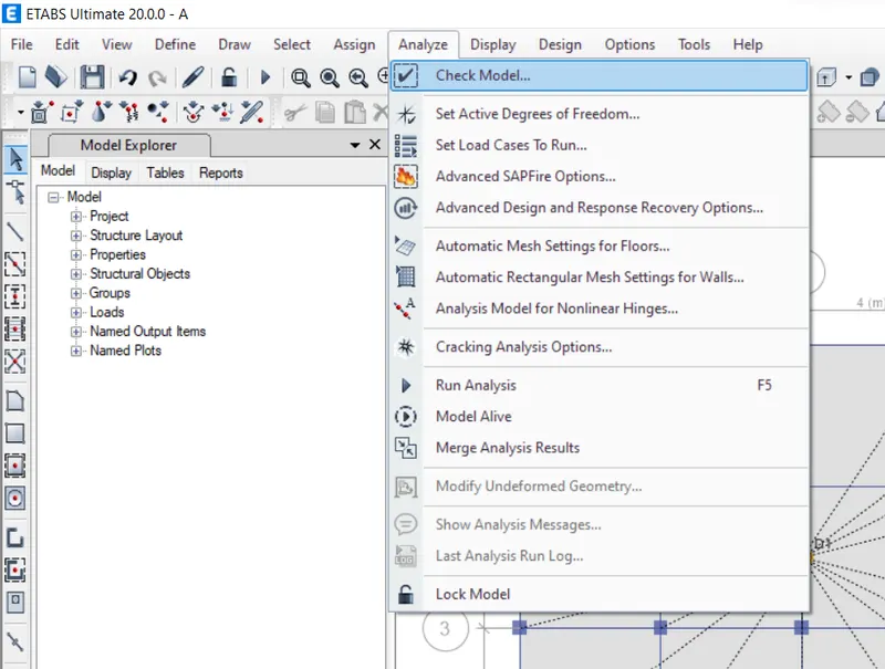
Click on Analyse Tab
Click on check Model
Check model dialogue box opens
Select All and press OK
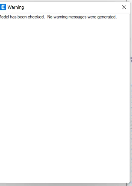
Warning dialogue box opens
No warnings have been generated.
Our model has no errors.
Click on Analyse Tab
Click on Run Analysis
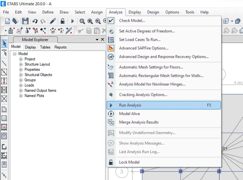
Go to Model Explorer on the screen
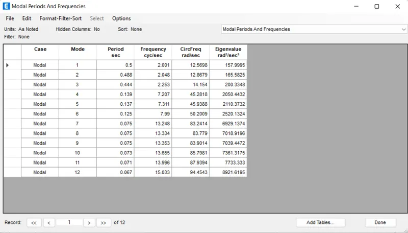
Click on Analysis Results
Click on Structure Output from the dropdown list
Click on modal information from the dropdown list
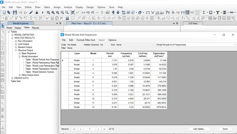
Select Table: Modal periods and Frequencies
MODEL-B
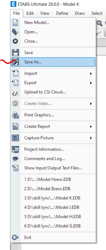
Click on FILE TAB
Click on Save as
Save the File as model B
Make the changes to the file as per given data
Click on EDIT TAB
Select Edit Stories and Grid Systems tool
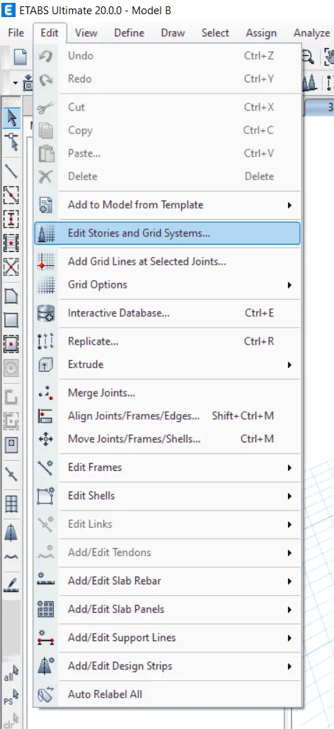
Edit Story and Grid System Data dialogue box opens
Click on Modify/Show Story Data option
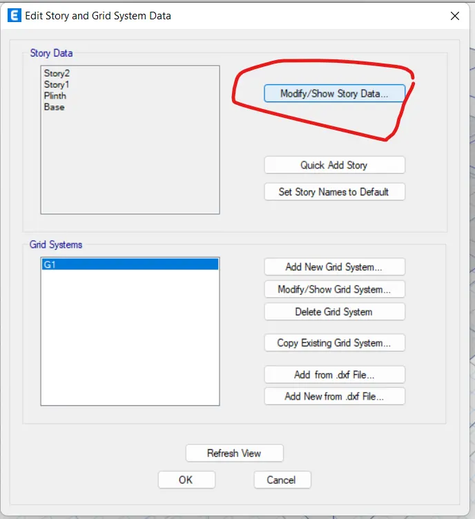
Story data dialogue box opens
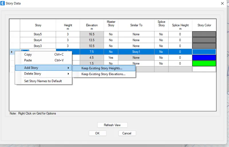
Right click on the story 3 and click on Add Story
Select keep Existing Story Heights option
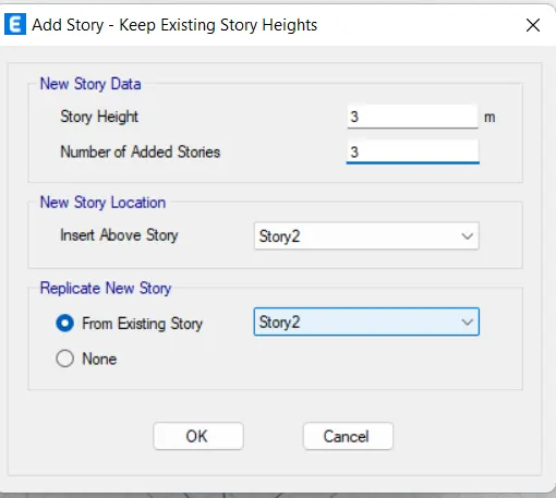
Add Story dialogue box opens
Enter the required data and press Ok
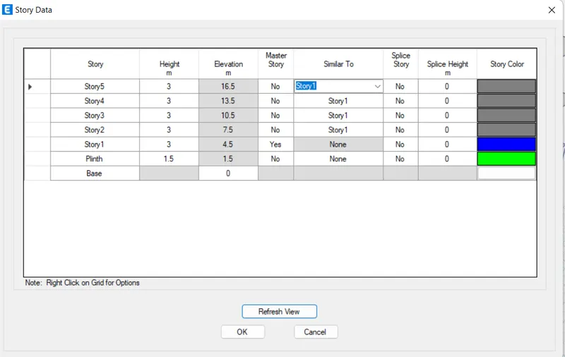
Select YES for the Story1 in Master Story column.
Select Story1 for the rest of the storeys in Similar To column
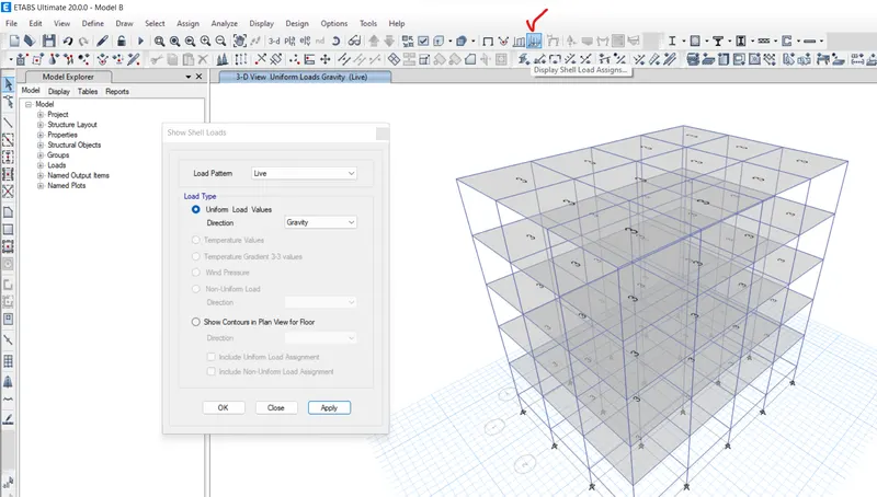
Click on the Display Shell Load icon on the screen to cross check whether live load is applied on all slabs.
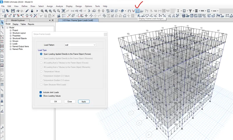
Click on the Display Frame Load icon on the screen to cross check whether wall load is applied on all beams.
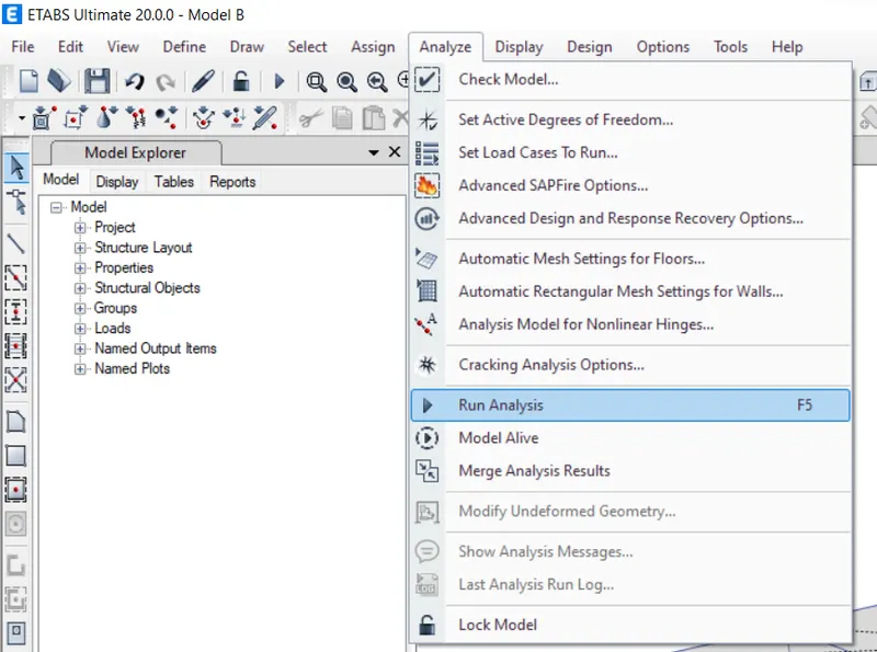
Click on Analyse Tab
Click on Run Analysis
Go to Model Explorer on the screen
Click on Analysis Results
Click on Structure Output from the dropdown list
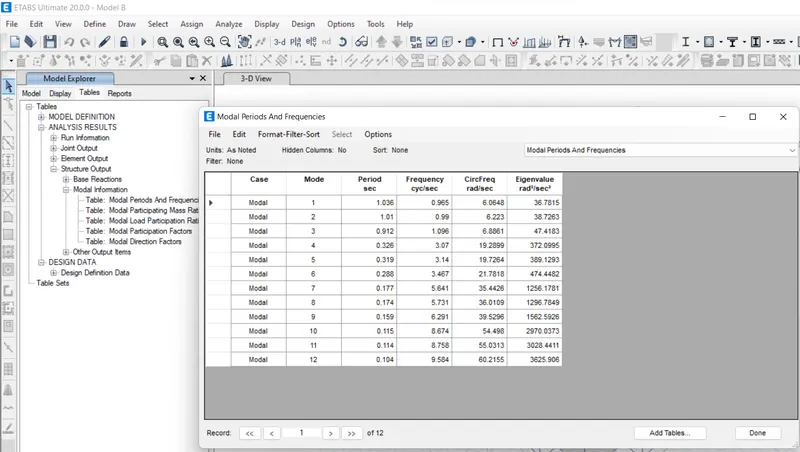
Click on modal information from the dropdown list
Select Table: Modal periods and Frequencies
MODEL-C
Click on FILE TAB
Click on Save as
Save the File as model C
Make the changes to the file as per given data
Click on the Define Tab
Click on Section Properties and select Frame Sections
Frame Properties dialogue box opens
Click on Add New Property
Frame Property Shape Type dialogue box opens
Section Shape: Concrete Rectangular
Click on Rectangle shape under Concrete
Frame Section Property data dialogue box opens
Enter the data
General Data
Propert Name: Column550x300
Material: M30
Section dimensions
Width: 300mm
Depth: 550mm
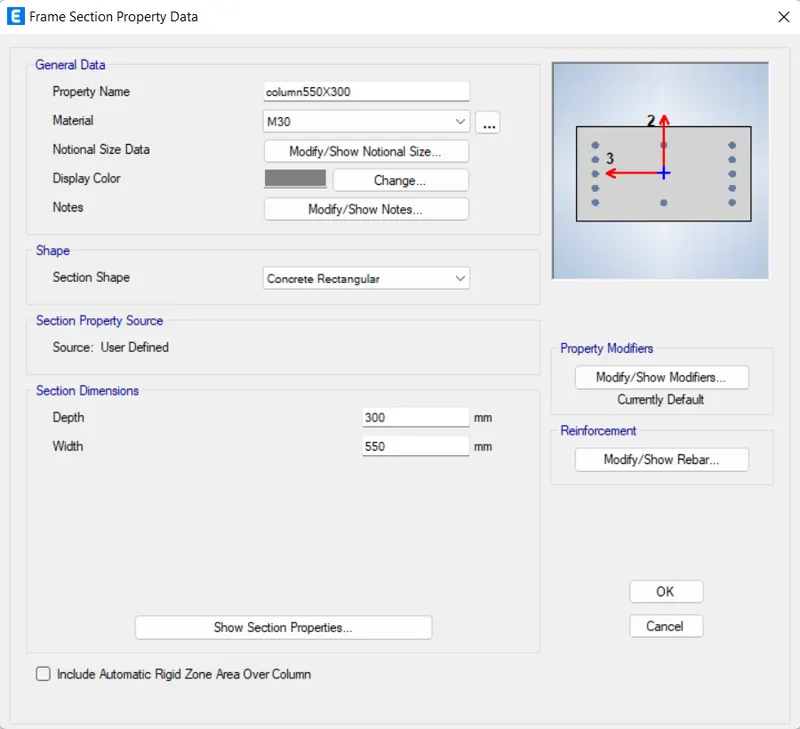
Frame Section Property Reinforcement data dialogue box opens
Design Type: P-M2-M3 Design(columns)
Rebar Material: HYSD415
Press Ok
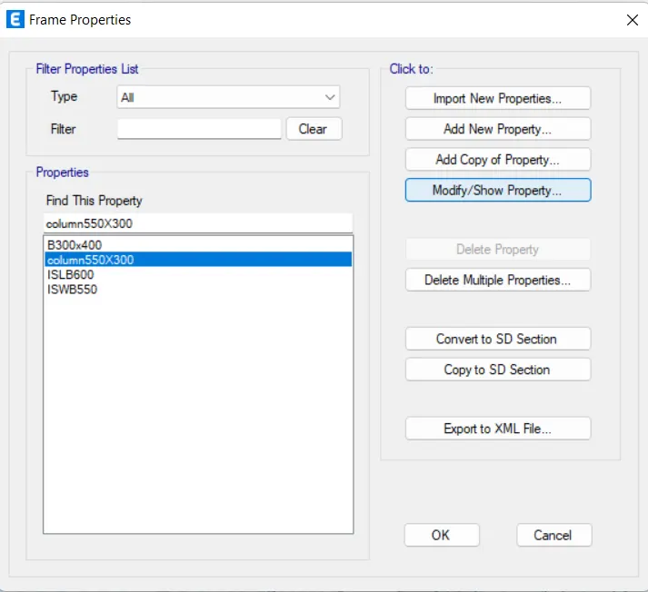
We can see the column550x300 in the Frame properties List
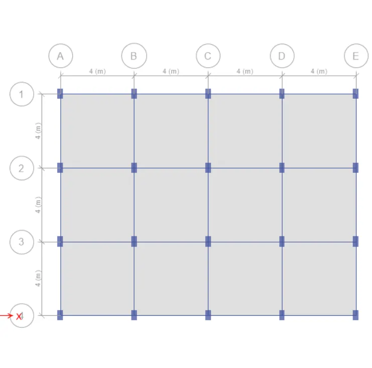
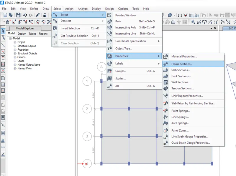
Click on SelectTab
Click on Select
Go to Properties from the list
Select Frame Sections
Select column550x300 from the list
Click on Assign Tab
Click on Frame
Select Local Axes
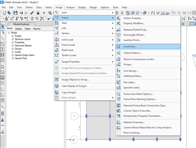
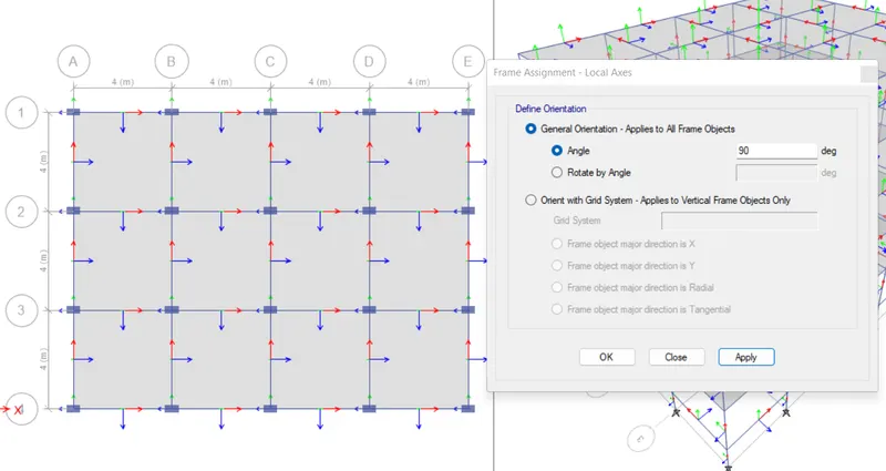
Frame Assignment dialogue box opens
General Orientation
Angle: 90 deg
Click on Apply
Press OK
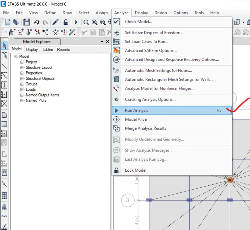
Click on Analyse Tab
Click on Run Analysis
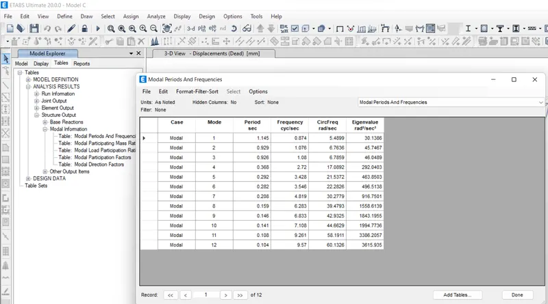
Go to Model Explorer on the screen
Click on Analysis Results
Click on Structure Output from the dropdown list
Click on modal information from the dropdown list
Select Table: Modal periods and Frequencies
MODEL-D
Click on FILE TAB
Click on Save as
Save the File as model D
Make the changes to the file as per given data
Click on SelectTab
Click on Select
Go to Properties from the list
Select Frame Sections
Select Column300x550 from the list
All the Columnss are selected
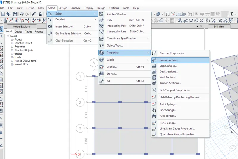
Click on Assign Tab
Click on Frame
Select Local Axes
Frame Assignment dialogue box opens
General Orientation
Angle: 0 deg
Click on Apply
Press OK
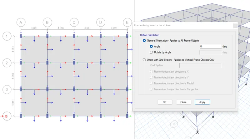
Click on Assign Tab
Click on shell tool
Select Diaphragms.
Shell Assignment- Diaphragms dialogue box opens
Select D1 in the list
Click on Apply and Press OK
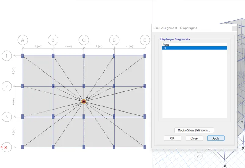
Click on Analyse Tab
Click on Run Analysis
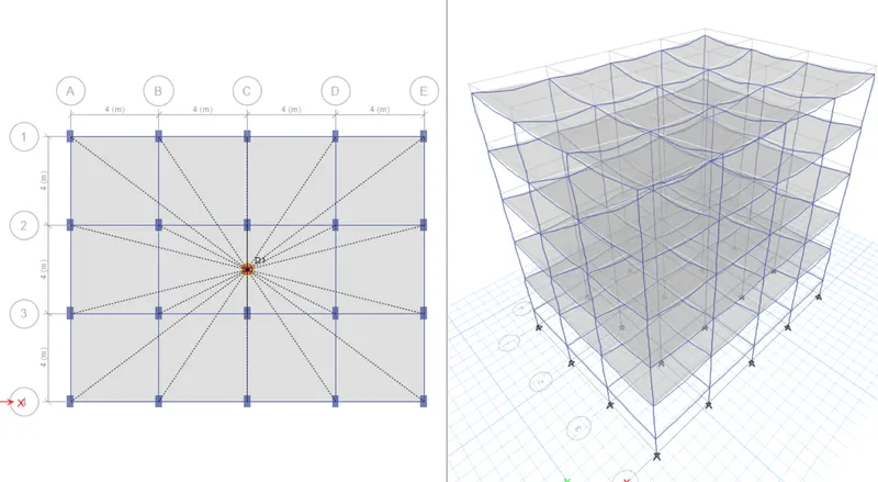
Go to Model Explorer on the screen
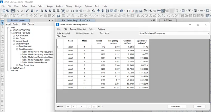
Click on Analysis Results
Click on Structure Output from the dropdown list
Click on modal information from the dropdown list
Select Table: Modal periods and Frequencies
MODEL-E
Click on FILE TAB
Click on Save as
Save the File as model E
Make the changes to the file as per given data
Click on EDIT TAB
Select Edit Stories and Grid Systems tool
Edit Story and Grid System Data dialogue box opens
Click on Modify/Show Story Data option
Story data dialogue box opens
Right click on the story 3 and click on Add Story
Select keep Existing Story Heights option
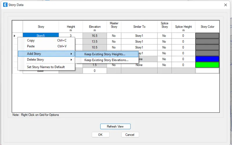
Add Story dialogue box opens
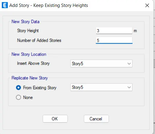
Enter the required data and press Ok
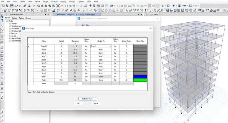
Select YES for the Story1 in Master Story column.
Select Story1 for the rest of the storeys in Similar To column
Click on the Define Tab
Click on Section Properties and select Frame Sections
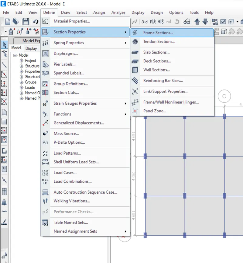
Frame Properties dialogue box opens
Click on modify/Show Property
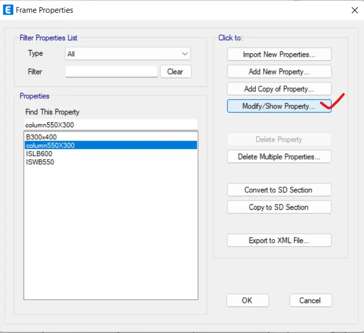
Enter the data
General Data
Propert Name: Column 600x600
Material: M30
Section dimensions
Width: 600mm
Depth: 600mm
Press OK
Click on the Define Tab
Click on Section Properties and select Frame Sections
Frame Properties dialogue box opens
Click on Add New Property
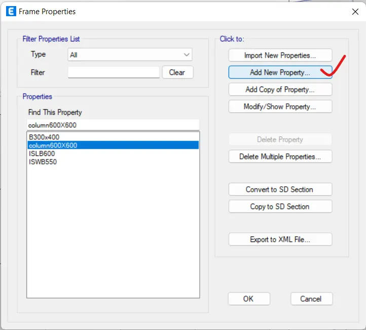
Frame Property Shape Type dialogue box opens
Section Shape: Concrete Rectangular
Click on Rectangle shape under Concrete
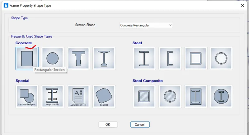
Frame Section Property data dialogue box opens
Enter the data
General Data
Propert Name: Column400x400
Material: M30
Section dimensions
Width: 400mm
Depth: 400mm
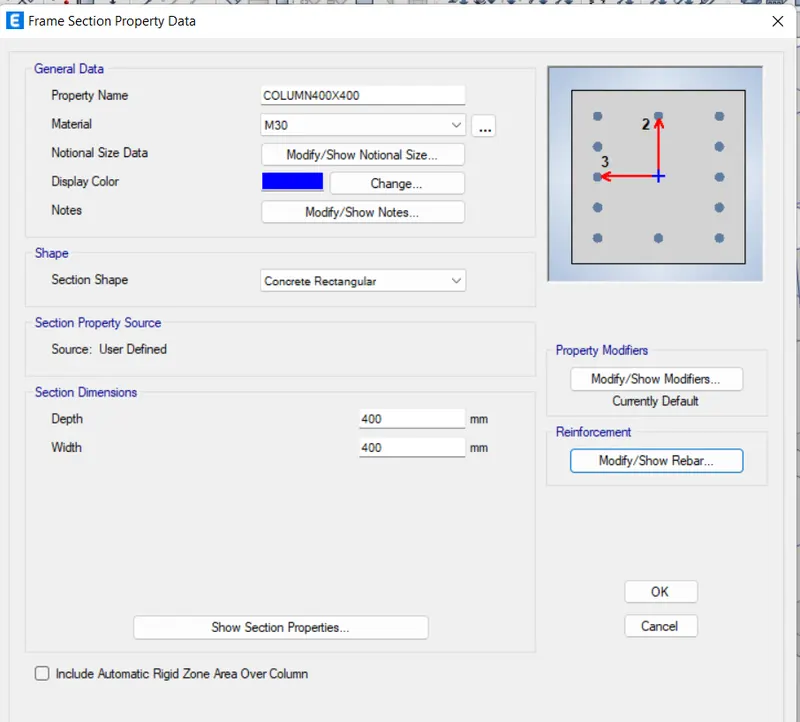
Click on Modify/Show Rebar option under Reinforcement
Frame Section Property Reinforcement data dialogue box opens
Design Type: P-M2-M3 Design(columns)
Rebar Material: HYSD415
Press Ok
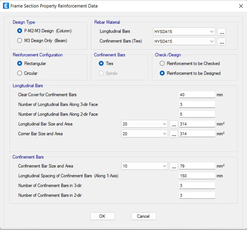
Click on VIEW TAB
Select Set Building View Limits from the dropdown list
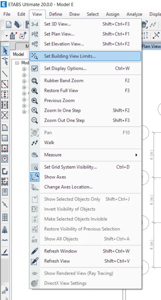
Set Building View Limits dialogue box opens
Set Story Range
Top Story: Story 10
Bottom Story: Story 6
Press OK
Click on Set Display option on the screen
Untick beams and Floors from the List
Click on Apply
Press OK
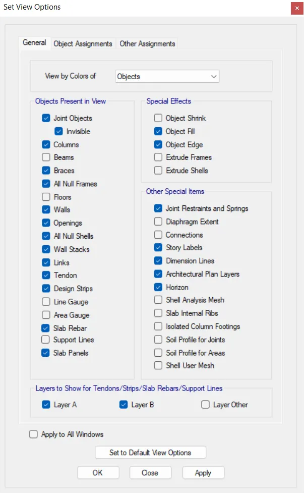
Select all the Columns on the Screen
Click on Assign Tab
Click on Frame
Select Section Property.
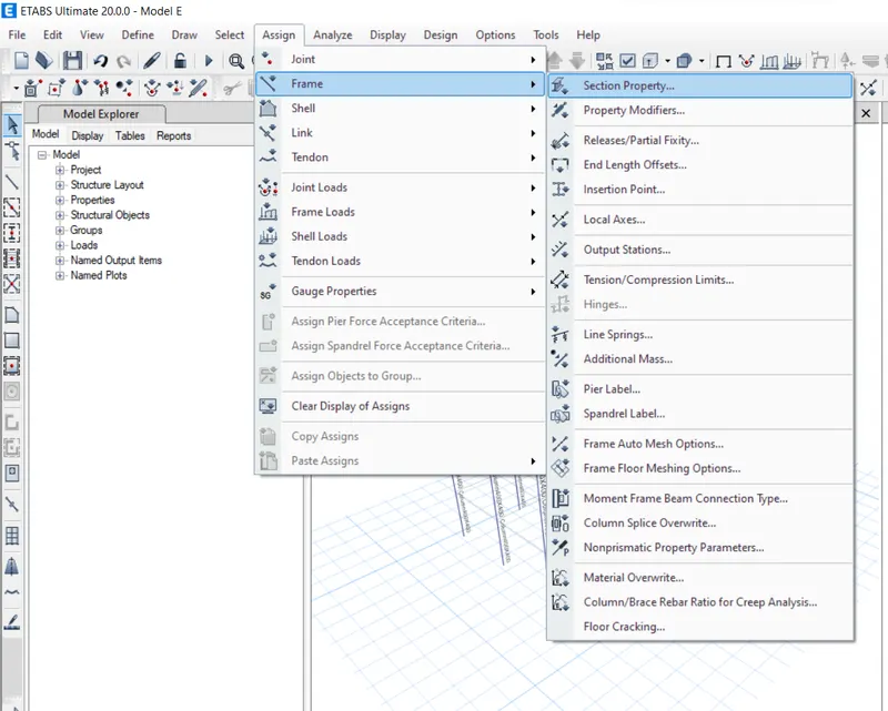
Frame Assignment-Section property dialogue box opens
Select Column400x400 section in the list.
Click on Apply
Press Ok
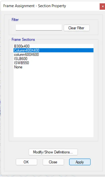
Column 400x400 is applied to the columns from the story 6 to Story 10.
Click on Set Display option on the screen
Tick diaphragms from the List
Click on Apply
Press OK
We confirmed that diaphragms are applied to all floors.
Click on Analyse Tab
Click on Run Analysis
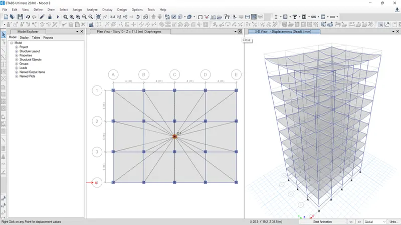
Go to Model Explorer on the screen
Click on Analysis Results
Click on Structure Output from the dropdown list
Click on modal information from the dropdown list
Select Table: Modal periods and Frequencies.
MODEL-F
Click on FILE TAB
Click on Save as
Save the File as model F
Make the changes to the file as per given data
Click on Set Display option on the screen
Untick beams and Floors from the List
Click on Apply
Press OK
Click on VIEW TAB
Select Set Building View Limits from the dropdown list
Set Building View Limits dialogue box opens
Set Story Range
Top Story: Story 10
Bottom Story: Story 6
Press OK
Click on Assign Tab
Click on Frame
Select Section property.
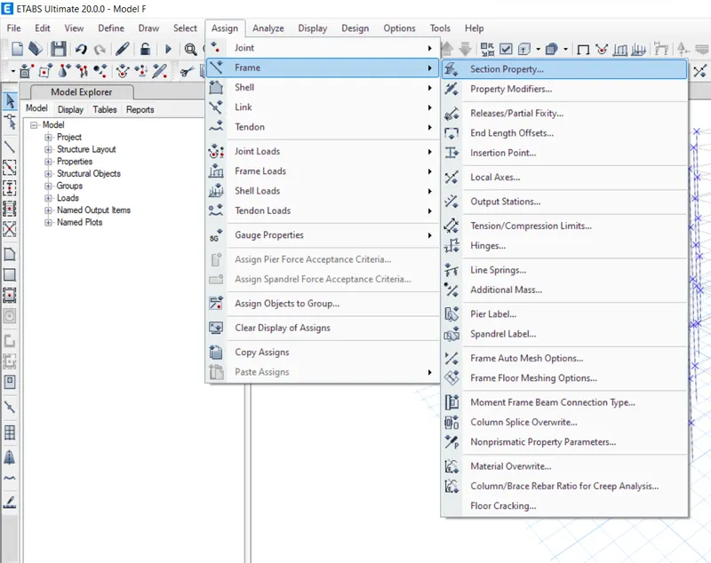
Frame Assignment-Section property dialogue box opens
Select Column600x600 section in the list.
Click on Apply
Press Ok
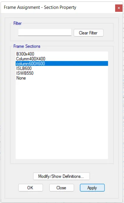
Column 600x600 is applied to the columns from the story 6 to Story 10.
Click on Set Display option on the screen
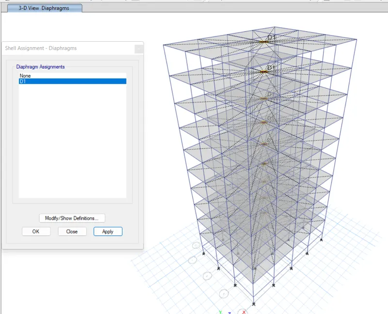
Tick diaphragms from the List
Click on Apply
Press OK
We confirmed that diaphragms are applied to all floors.
Click on Analyse Tab
Click on Run Analysis
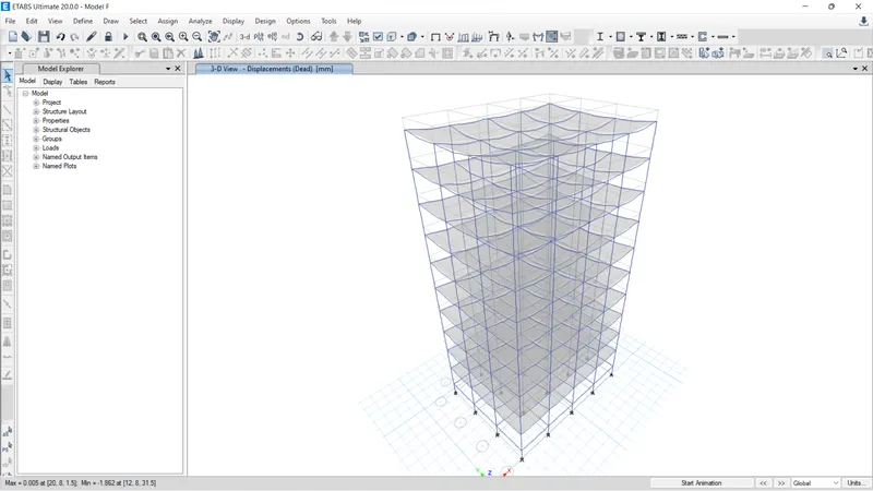
Go to Model Explorer on the screen
Click on Analysis Results
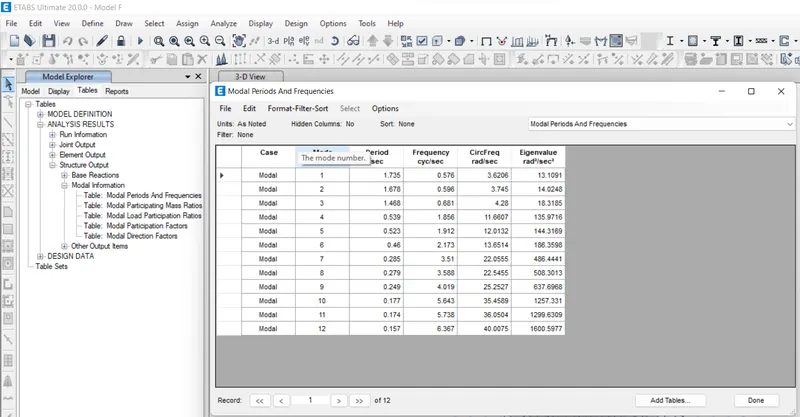
Click on Structure Output from the dropdown list
Click on modal information from the dropdown list
Select Table: Modal periods and Frequencies.
MODEL-G
Click on FILE TAB
Click on Save as
Save the File as model G
Make the changes to the file as per given data
Click on Set Display option on the screen
Untick beams and Floors from the List
Click on Apply
Press OK
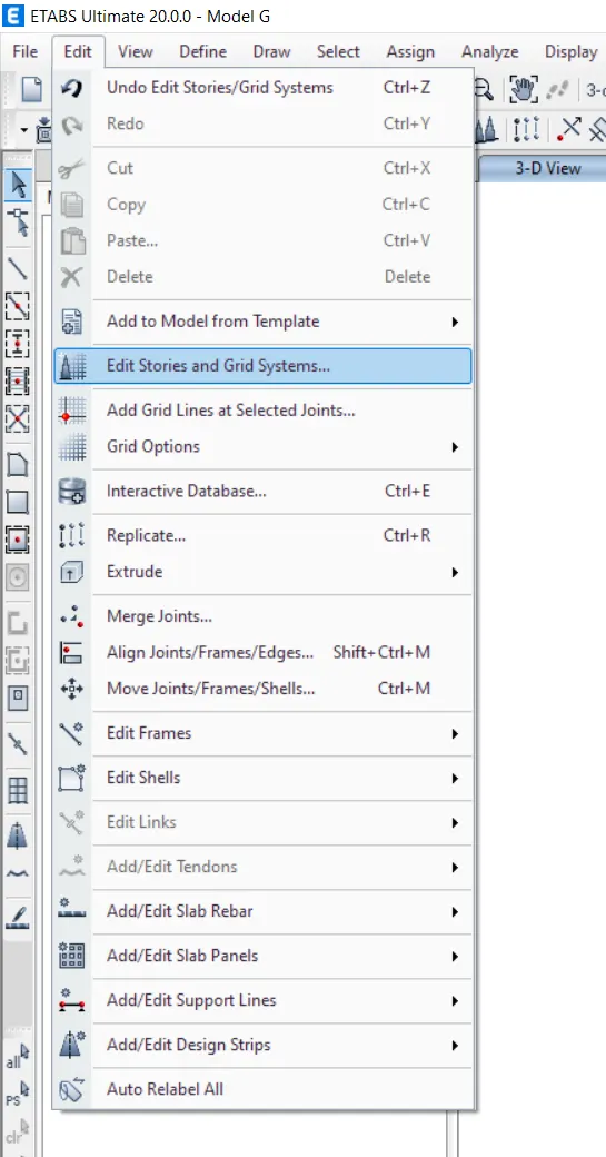
Click on Edit Stories and Grid Systems
Click on Modify/Show Story Data
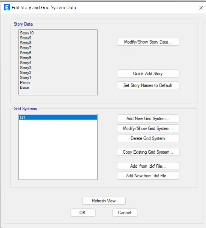
Story Data dialogue box opens
Right click on the story 10 and click on Add Story
Select keep Existing Story Heights option
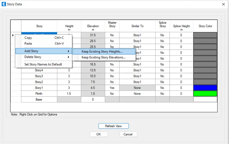
Add Story dialogue box opens
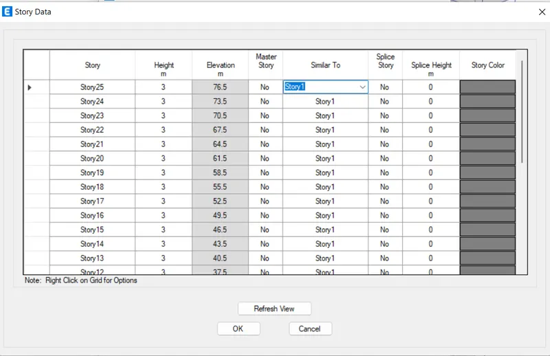
Enter the required data and press Ok
Select YES for the Story1 in Master Story column.
Select Story1 for the rest of the storeys in Similar To column
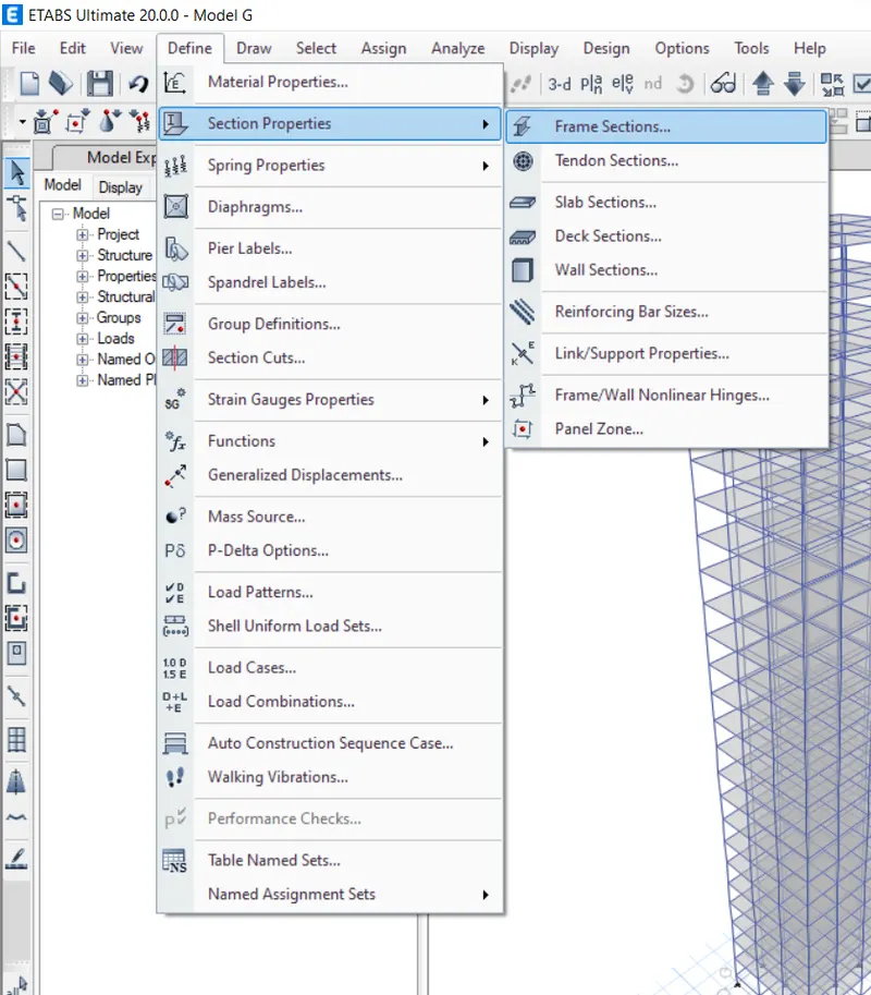
Click on the Define Tab
Click on Section Properties and select Frame Sections
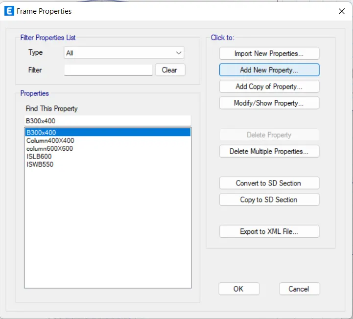
Frame Properties dialogue box opens
Click on Add New Property
Frame Property Shape Type dialogue box opens
Section Shape: Concrete Rectangular
Click on Rectangle shape under Concrete
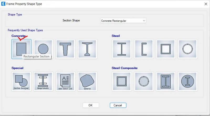
Frame Section Property data dialogue box opens
Enter the data
General Data
Propert Name: Column800x800
Material: M30
Section dimensions
Width: 800mm
Depth: 800mm
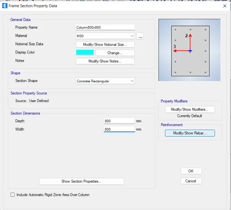
Click on Modify/Show Rebar option under Reinforcement
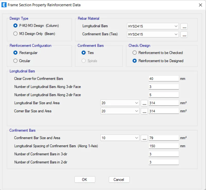
Frame Section Property Reinforcement data dialogue box opens
Design Type: P-M2-M3 Design(columns)
Rebar Material: HYSD415
Press Ok
Click on VIEW TAB
Select Set Building View Limits from the dropdown list
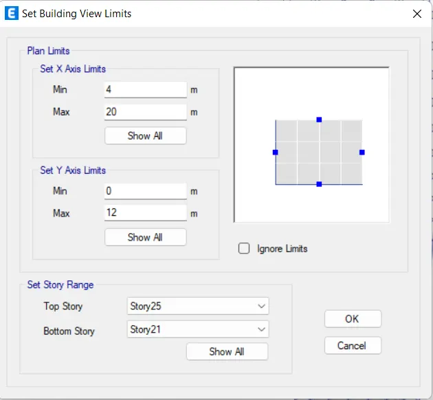
Set Building View Limits dialogue box opens
Set Story Range
Top Story: Story 25
Bottom Story: Story 21
Press OK
Select the all the columns from Story 21 to Story 25
Click on Assign Tab
Click on Frame
Select Section property.
Frame Assignment-Section property dialogue box opens
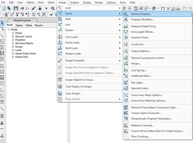
Select Column400x400 section in the list.
Click on Apply
Press Ok
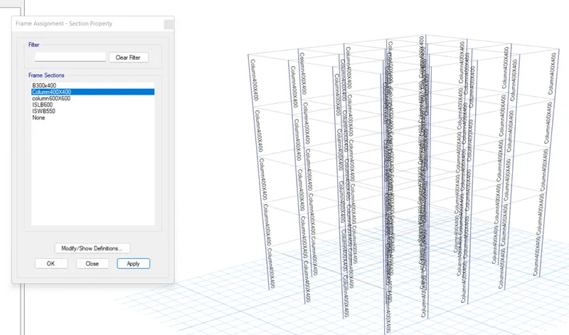
Column400x400 Section is applied to the Selected columns.
Click on VIEW TAB
Select Set Building View Limits from the dropdown list
Set Building View Limits dialogue box opens
Set Story Range
Top Story: Story 10
Bottom Story: Base
Press OK
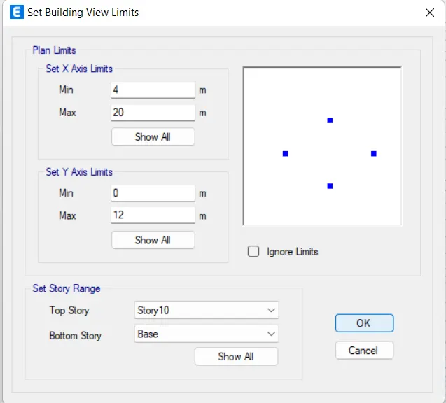
Select all the columns from story 10 to Base story
Click on Assign Tab
Click on Frame
Select Section property.
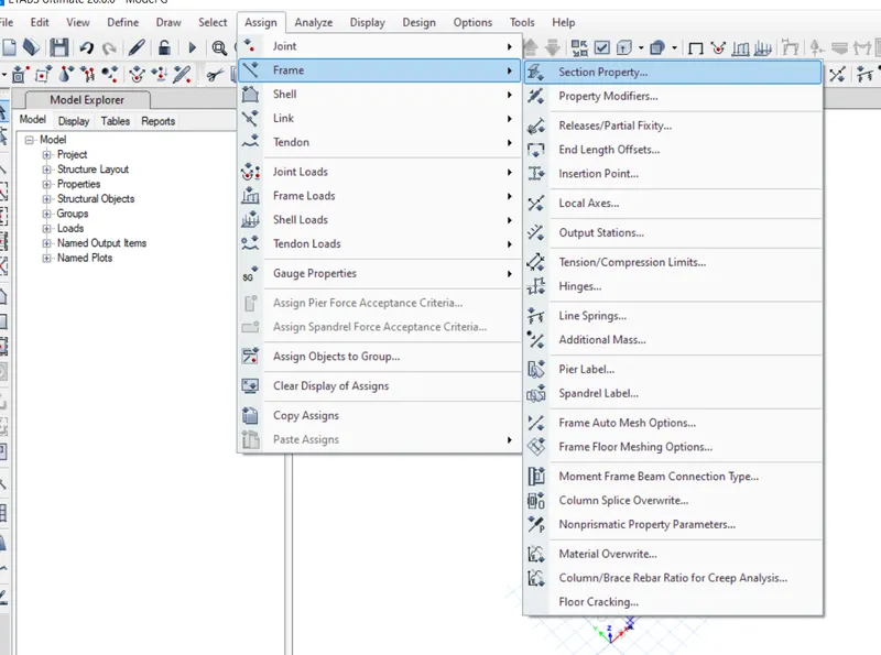
Select Column800x800 section in the list.
Click on Apply
Press Ok
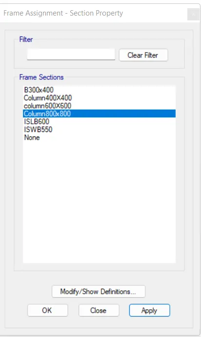
Column800x800 Section is applied to the Selected columns.
Click on Analyse Tab
Click on Run Analysis
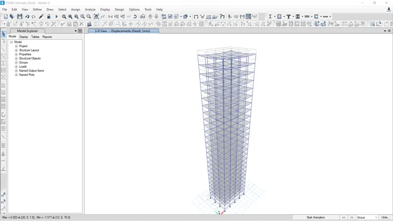
Go to Model Explorer on the screen
Click on Analysis Results
Click on Structure Output from the dropdown list
Click on modal information from the dropdown list
Select Table: Modal periods and Frequencies.
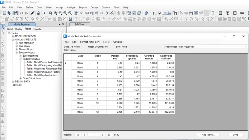
MODEL-H
Click on FILE TAB
Click on Save as
Save the File as model H
Make the changes to the file as per given data
Click on Set Display option on the screen
Untick beams and Floors from the List
Click on Apply
Press OK
Click on VIEW TAB
Select Set Building View Limits from the dropdown list
Set Building View Limits dialogue box opens
Set Story Range
Top Story: Story 25
Bottom Story: Story 11
Press OK
Select the all the columns from Story 11 to Story 25 on the screen
Click on Assign Tab
Click on Frame
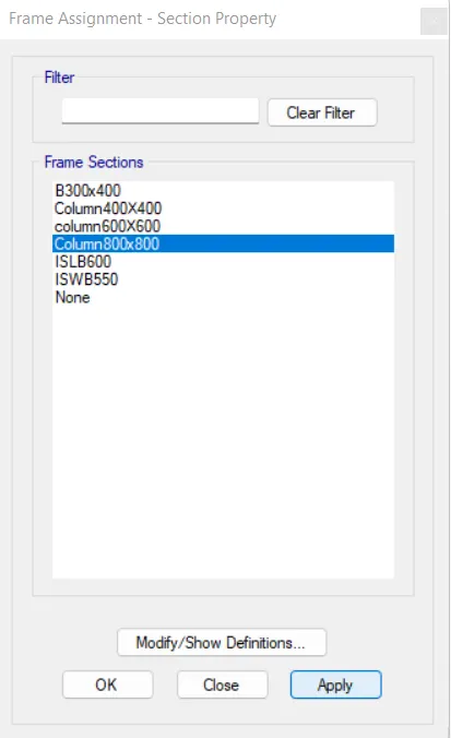
Select Section property.
Frame Assignment-Section property dialogue box opens
Select Column800x800 section in the list.
Click on Apply
Press Ok
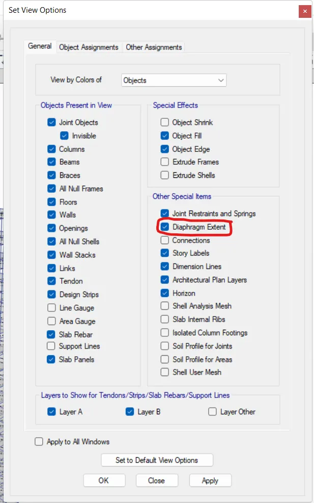
Click on Set Display option on the screen
Tick diaphragms from the List
Click on Apply
Press OK
Click on Analyse Tab
Click on Run Analysis
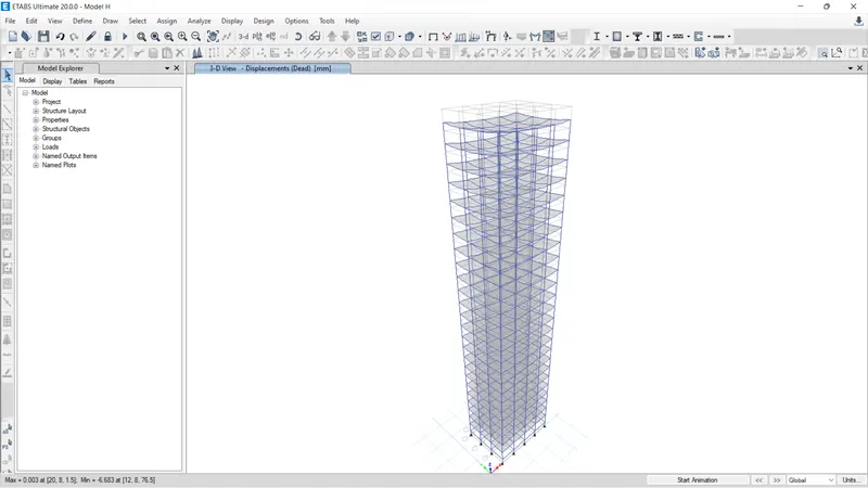
Go to Model Explorer on the screen
Click on Analysis Results
Click on Structure Output from the dropdown list
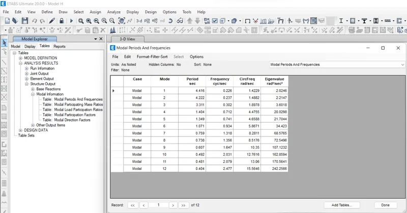
Click on modal information from the dropdown list
Select Table: Modal periods and Frequencies.
MODEL-J
Click on FILE TAB
Click on Save as
Save the File as model J
Make the changes to the file as per given data
Click on Assign Tab
Click on shell Loads
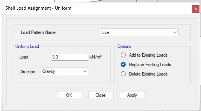
Select Uniform option.
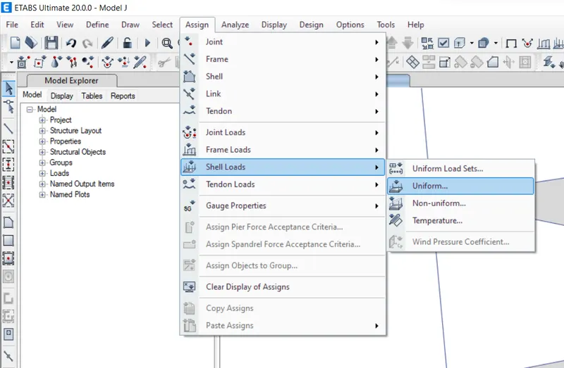
Shell load Assignment-Uniform dialogue box opens
Load Pattern: live load
Load: 3.3 Kn/m
Click Apply and Press OK
Click on Set Display option on the screen
Tick diaphragms from the List
Click on Apply
Press OK
Click on Analyse Tab
Click on Run Analysis
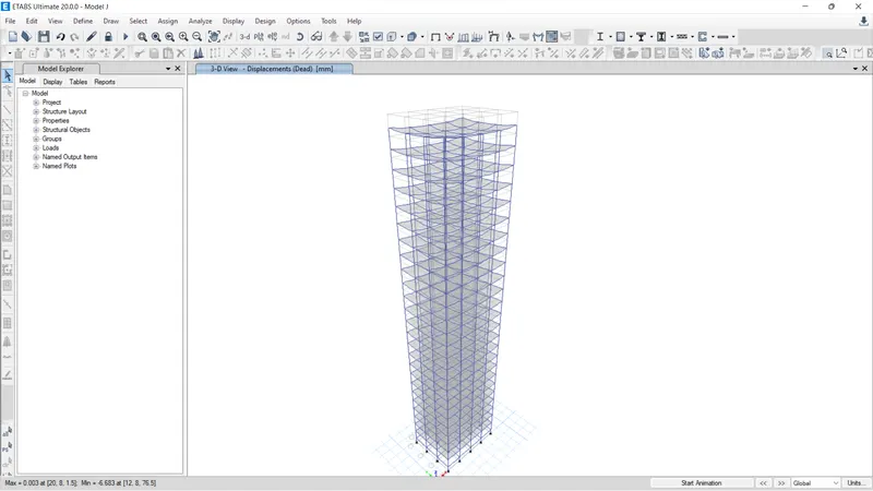
Go to Model Explorer on the screen
Click on Analysis Results
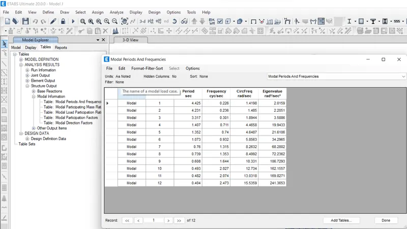
Click on Structure Output from the dropdown list
Click on modal information from the dropdown list
Select Table: Modal periods and Frequencies.
MODEL-K
Click on FILE TAB
Click on Save as
Save the File as model K
Make the changes to the file as per given data
Click on Assign Tab
Click on shell Loads
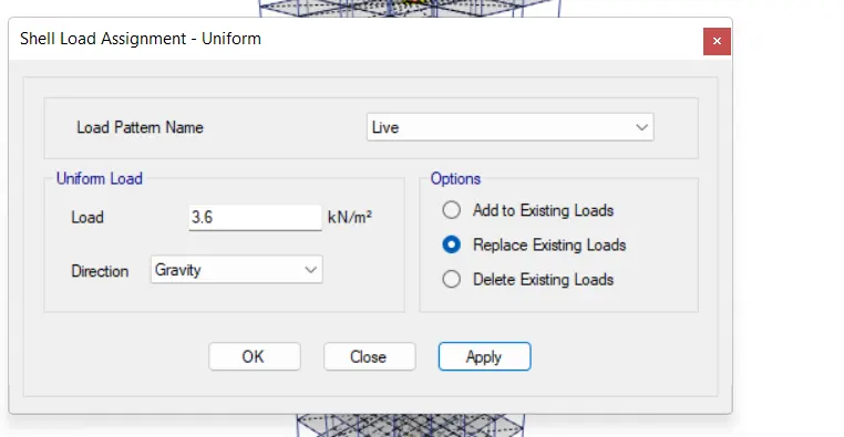
Select Uniform option.
Shell load Assignment-Uniform dialogue box opens
Load Pattern: live load
Load: 3.6 Kn/m
Click Apply and Press OK
Click on Set Display option on the screen
Tick diaphragms from the List
Click on Apply
Press OK
Click on Analyse Tab
Click on Run Analysis
Go to Model Explorer on the screen
Click on Analysis Results
Click on Structure Output from the dropdown list
Click on modal information from the dropdown list
Select Table: Modal periods and Frequencies.
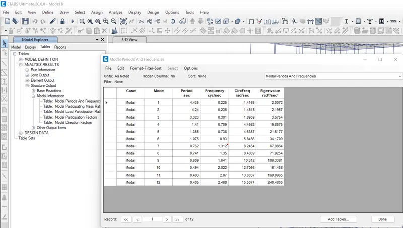
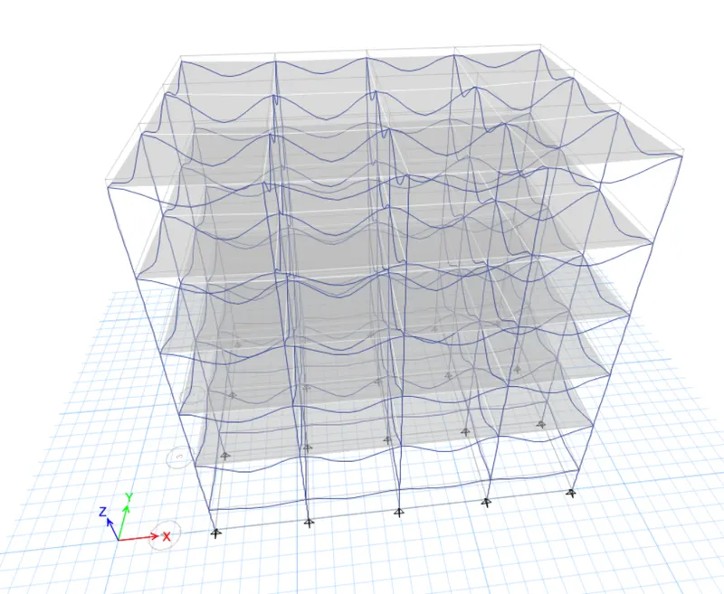
MODEL Bzero Axial Stiffness of Column close to NIL
Click on FILE TAB
Open the Model B
Click on Save as
Save the File as Model Bzero
Make the changes to the file as per given data
Click on the Define Tab
Click on Section Properties and select Frame Sections
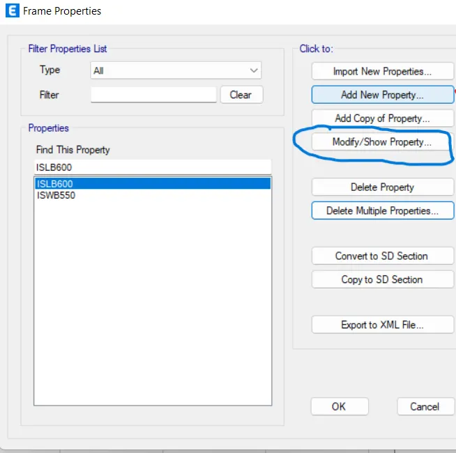
Frame Properties dialogue box opens
select the Beam 300x400
Click on Modify/Show Property
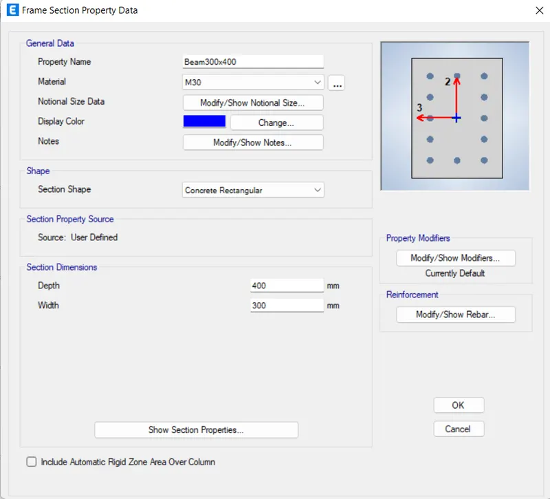
Frame Section Property Data dialogue box opens
Under Property Modifiers, click on Modify/show modifiers
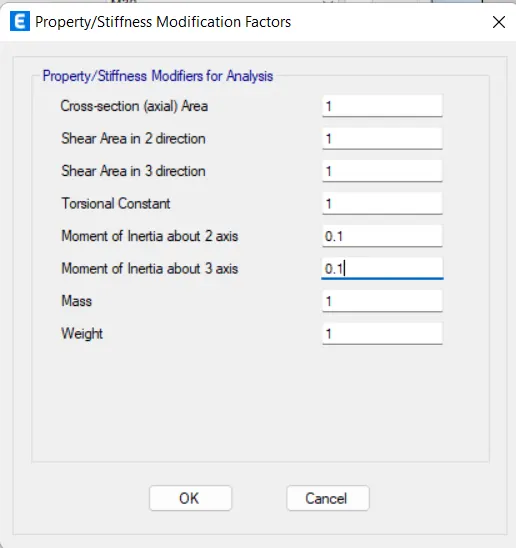
property/Stiffness Modification factors dialogue box opens
moment of inertia about 2 axis: 0.1
moment of inertia aout 3 axis: 0.1
press Ok
Click on Analyse Tab
Click on Run Analysis
Go to Model Explorer on the screen
Click on Analysis Results
Click on Structure Output from the dropdown list
Click on modal information from the dropdown list
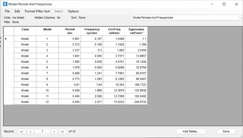
Select Table: Modal periods and Frequencies
MODEL Hzero - flexural stiffness of Beam close to NIL
Click on FILE TAB
Open the Model H
Click on Save as
Save the File as Model Hzero
Make the changes to the file as per given data
Click on the Define Tab
Click on Section Properties and select Frame Sections
Frame Properties dialogue box opens
select the Column
Click on Modify/Show Property
Frame Section Property Data dialogue box opens
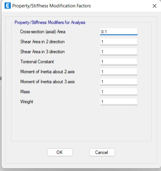
Under Property Modifiers, click on Modify/show modifiers
property/Stiffness Modification factors dialogue box opens
Cross Section Axial Area: 0.1
press Ok
Click on Analyse Tab
Click on Run Analysis
Go to Model Explorer on the screen
Click on Analysis Results
Click on Structure Output from the dropdown list
Click on modal information from the dropdown list
Select Table: Modal periods and Frequencies
RESULT: -
We created all the given 10 models in ETABS.
We noted down the Time periods of all the models.
We compared the Analysis results for each of the criteria.
Identified the reasons for the influences and reported in tabulation form.
Factors influencing the Natural Period of a building
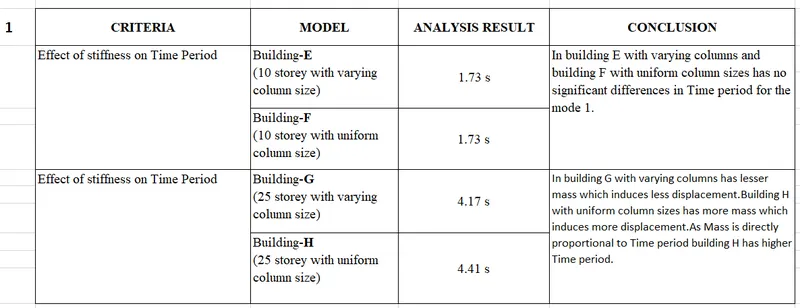
- Effect of stiffness on T:
- Compared fundamental natural periods of buildings E & F as well as G & H.
- We observed and noted down what could be the factors affecting for the differences in the Time period.
- Effect of mass on T:
- Compared fundamental natural periods of buildings H, J and K.
- We noted down observations about buildings become more flexible or stiff due to change in mass.
- Effect of Building Height on T:
- Compared fundamental natural periods of buildings A,B,F and H.
- We observed and noted How fundamental natural periods of Buildings A, B, F and H change with change in building height
- Effect of Column Orientation on T:
- Compared fundamental natural periods of buildings B,C and D.
- We observed and drawn conclusion about change in the fundamental natural periods of Buildings B, C and D with change in column orientation
Factors influencing the Mode shape of oscillations
- Effect of Flexural Stiffness of Structural Elements on mode shapes:
- Compared fundamental mode shape of Building B in two situations when flexural stiffness of beams relative to that of adjoining columns is very small versus when it is large.

- Effect of Axial Stiffness of Vertical Members on mode shapes:
- Compared fundamental mode shape of Building H in two situations when axial cross-sectional area of columns is very small versus when it is large.

- Effect of Degree of Fixity at column bases on mode shape:
- Compared fundamental mode shape of Building B in two situations when base of columns is pinned versus when it is fixed.
