Project 1_Comparative study of different storey buildings for Seismic forces
Project 1_Comparative study of different storey buildings for Seismic forces
Jagadeep.M.M
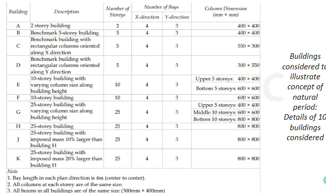
AIM: To analysis 10 different Buildings with same Beam size but different column size & find the modal time poeriod of each building for given condition.
Procedure:
Building A:
- Open the ETABS software & click on the new model.
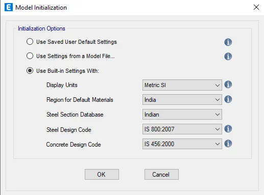
- The model initiation box will appear to select the use built-in setting with & modify it then press ok.
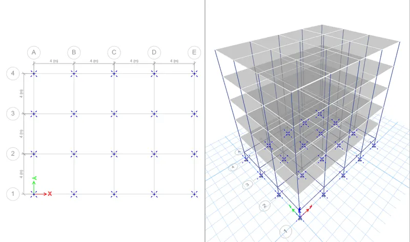
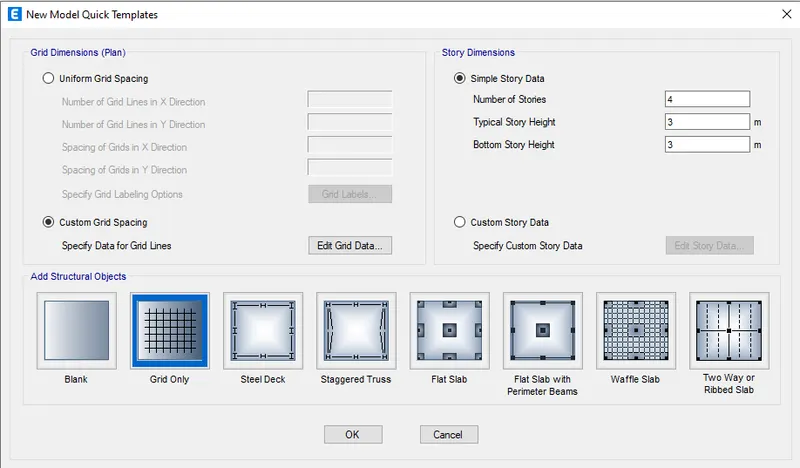
- In New model Quick Templates click on custom grid spacing & enter X,Y grid data as shown below.
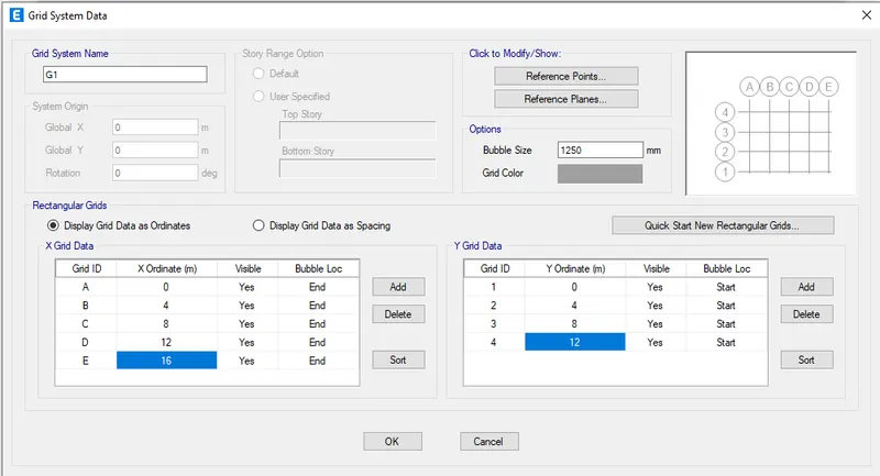
- Press ok.
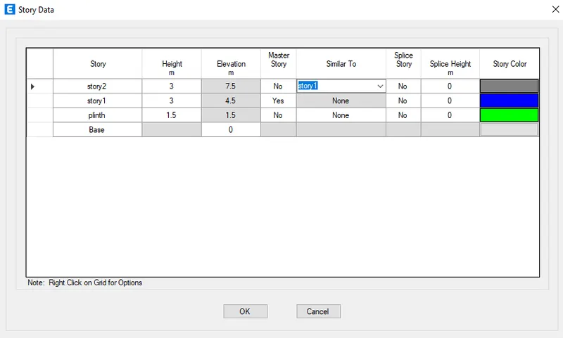
- Next click the storey & create 2 storeys with ech storey height of 3m & plinth level height as 1.5m.
- change the master "story 1" as "yes" & remaining storeys as "No".
- Change the "similar" to "storey 1" .
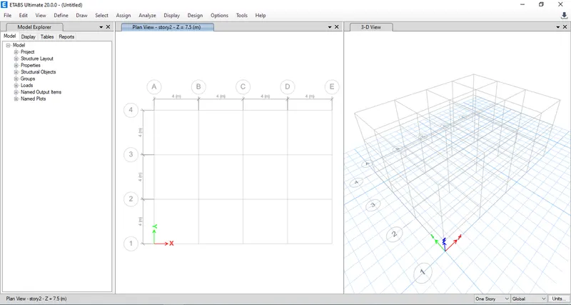
- Now go to "Define" for assigning the properties.
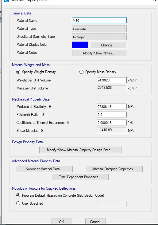
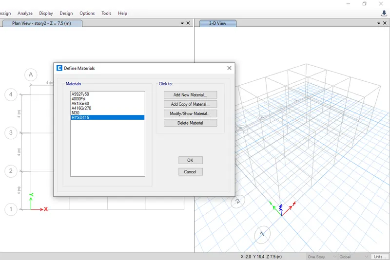
- Click on Material properties.
- Click on "add new materials" (for concrete).

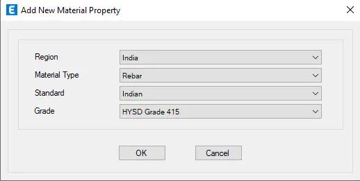
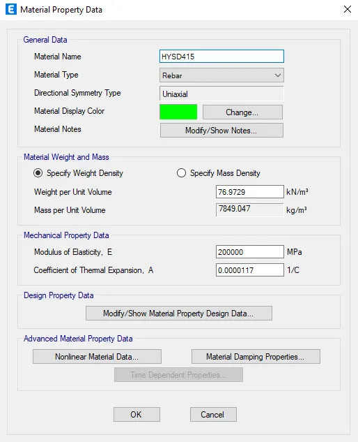
- Similar add another material for steel reinforcement bars.
- Define BEAM,SLAB,COLUMN.
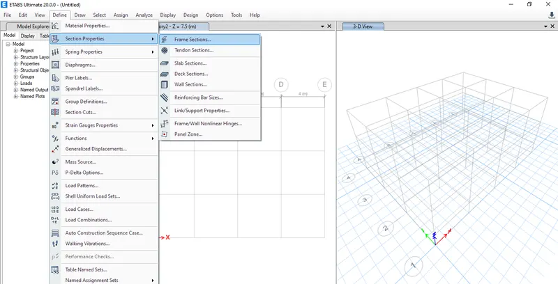
- Click on define & select sectin prooerties.
- Select the frame sections.
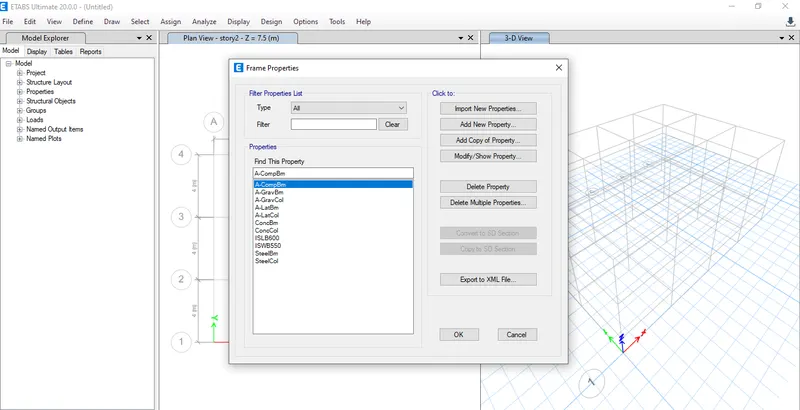
- Select the frame properties.
- Choose "Add properties" & select concrete.
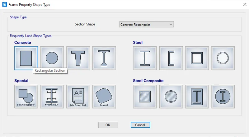
- Frame section property data appears in which enter details to the beam.
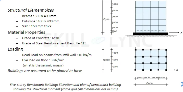
- Beam size taken as 300mmX400mm.
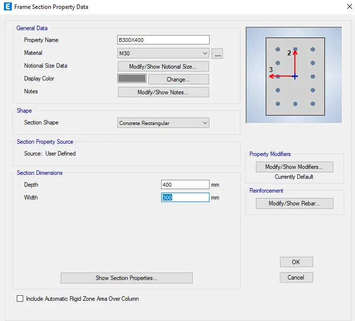
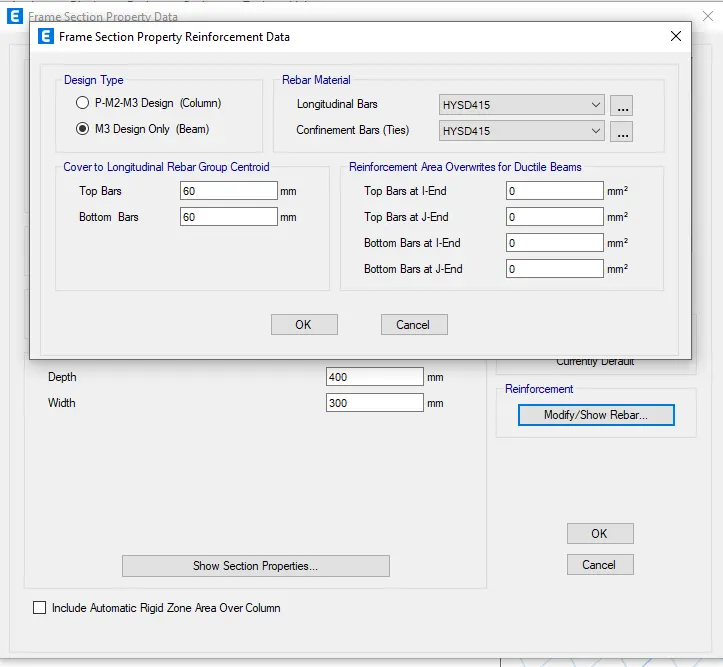
- Frame section property data appears in which enter details to the column.
- column size taken as 400mmX400mm.
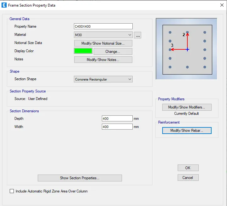
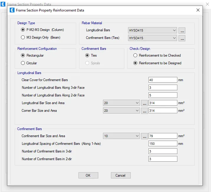
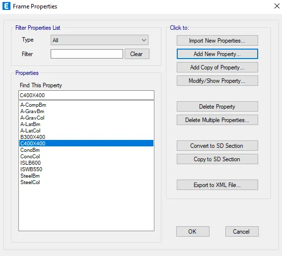
- Now design slab properties.
- Click on define,go to section properties & select slab properties.
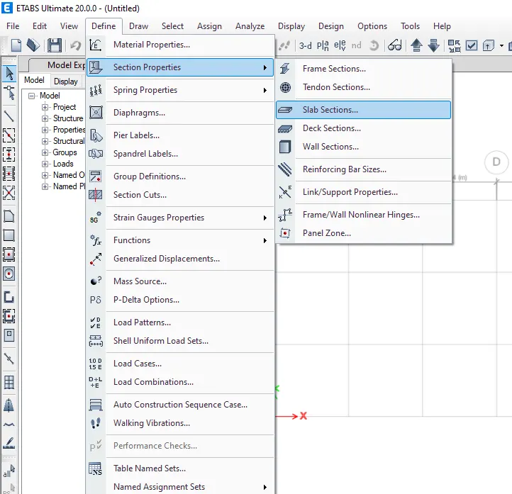
- Click on the add new property & modify it.
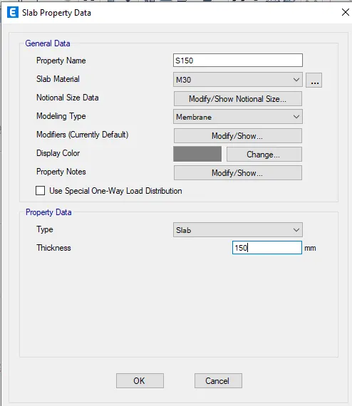
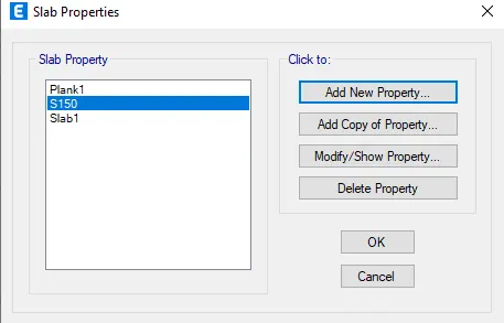
- Define the loads, click on "Define" then select "Load patterns".
- Enter brick wall load as a super dead load & add it as new load.
- Similarly add sesimic loads.
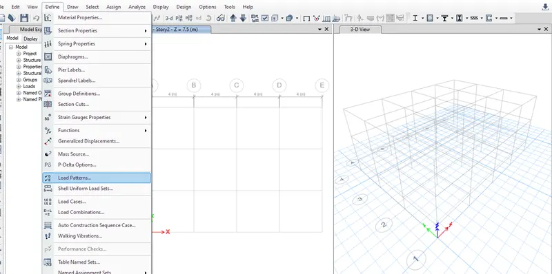
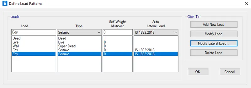
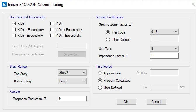
- Modify the seismic loads as shown below in EQX.
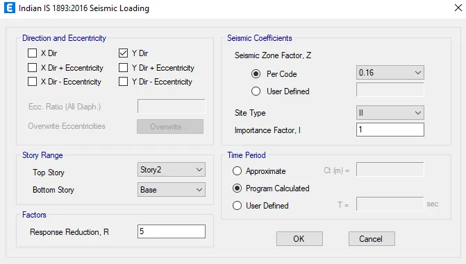
- Modify the seismic loads as shown below in EQY.
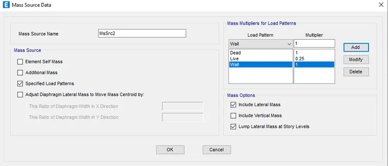
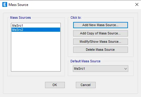
- Assign the mass source.
- Go to "Define" select mass source, click on modify.
- Select only "Specified load patterns".
- Add dead load,brick wall load,live load click ok.
- Live load of the multiplier of 25%.press ok
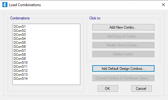
- Click on the "load combination".
- go to "Define", select load combination.
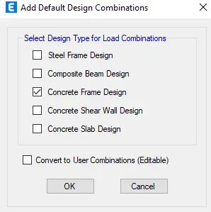
- Select add default design combos.
- Select concrete fram design.
- Select convert to user combination & click ok.
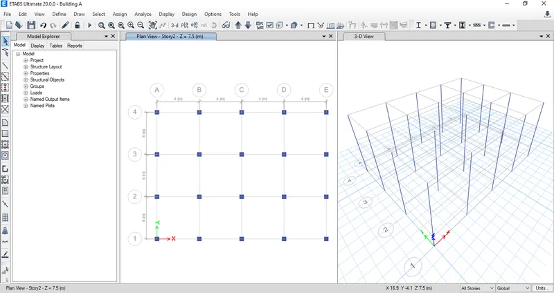
- Click on draw column,select 400X400 column & draw column for all storeys.
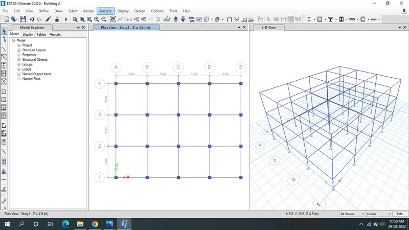
- Click on draw column,select 300X400 beam & draw beam for all storeys.
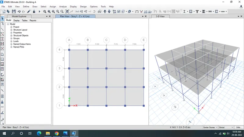
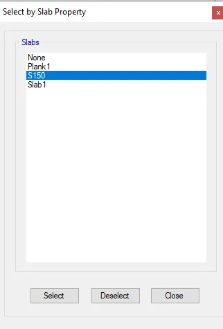
- Click on the Quick draw floor & select the slab 150 & assign.
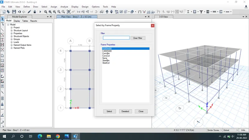
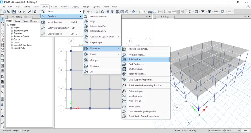
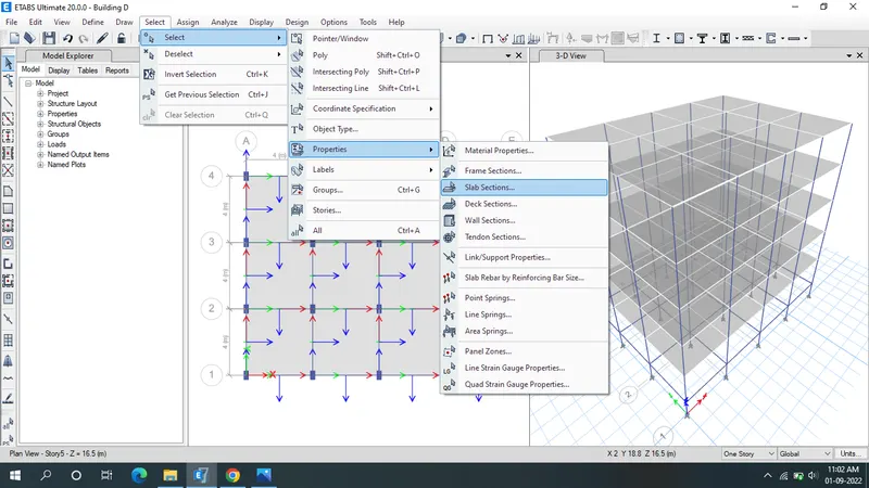
- Go to "select" option & click the "properties".
- Then select the "fram sections".
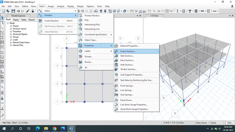
- select the beam 300X400.
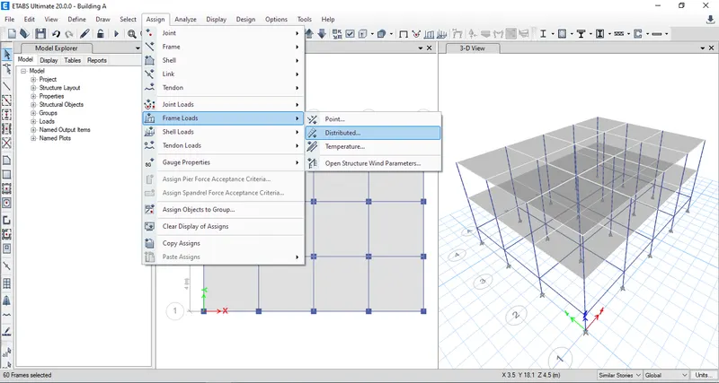
- Click the "assign" & select the fram loads.
- Then select the Distributed.
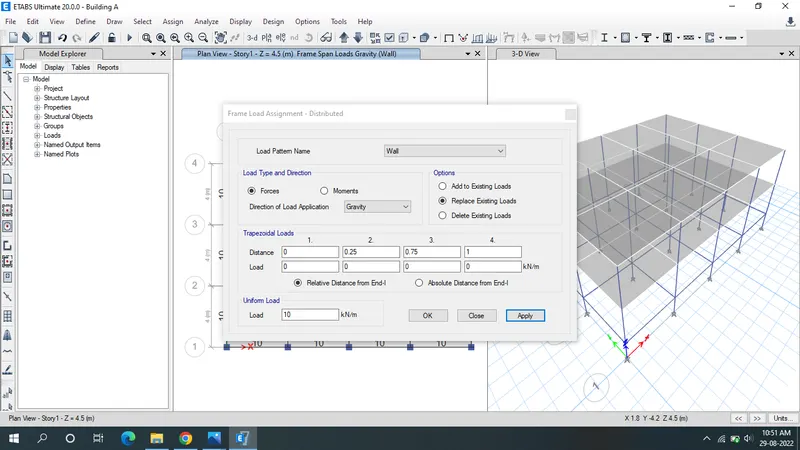
- Load pattern name as Brick wall.
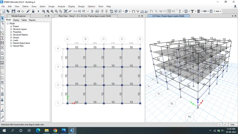
- Uniform load as 10KN/m, apply ,ok.
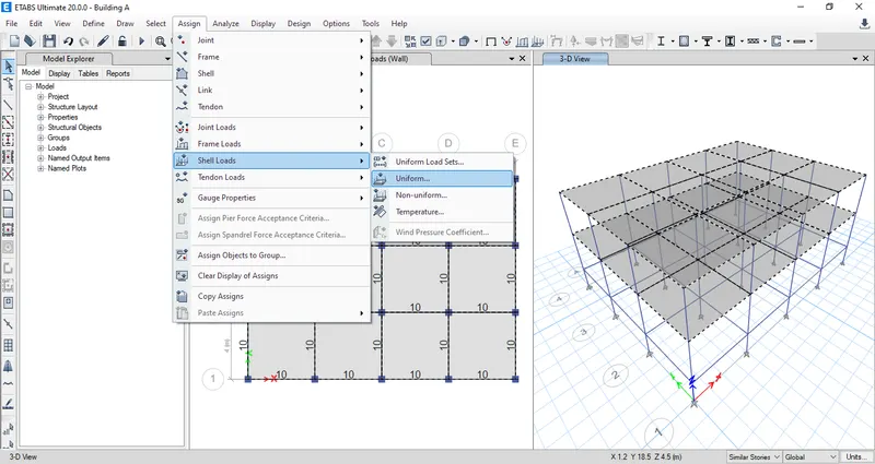
- Click the "Assign" & select the shell loads.
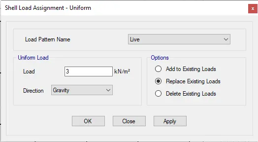
- Click the "uniform", Add the load pattern name as "Live".
- Uniform load as 3KN/m2, apply, ok.
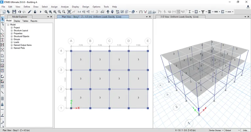
- Again select the slab.
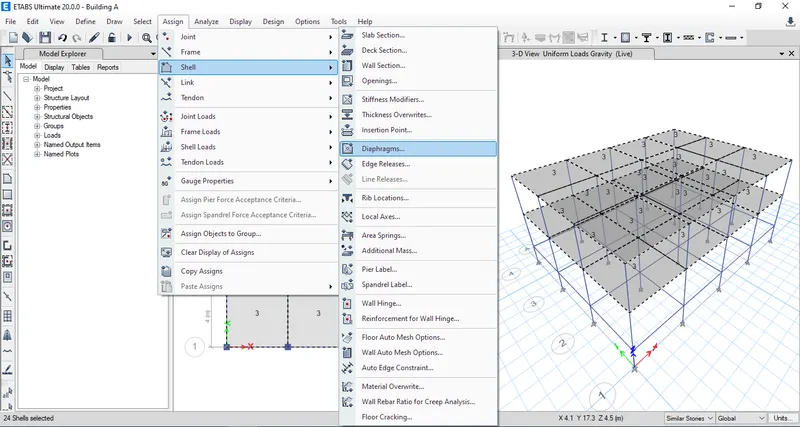
- Click the "Assign" select the shell.
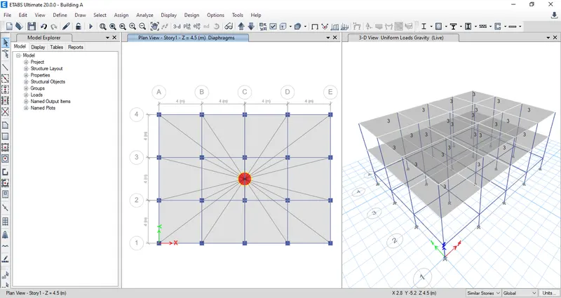
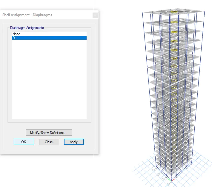
- Then select the "Diaphagms".
- Click the D1 & apply,ok
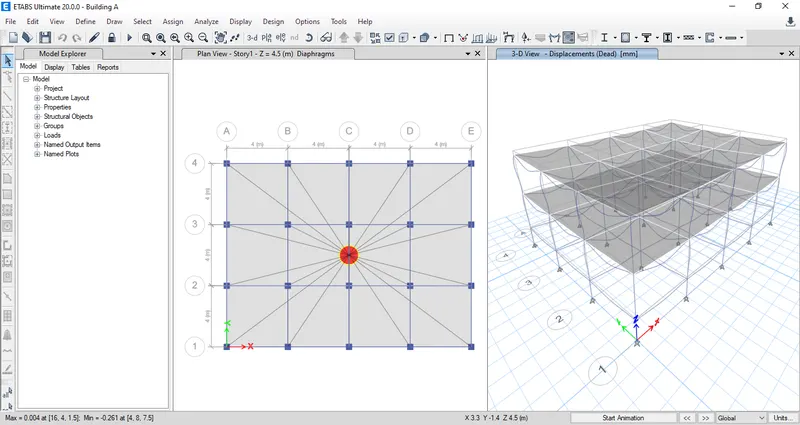
- Click the run Analysis.
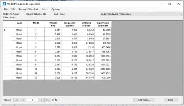
- Result will shown below.
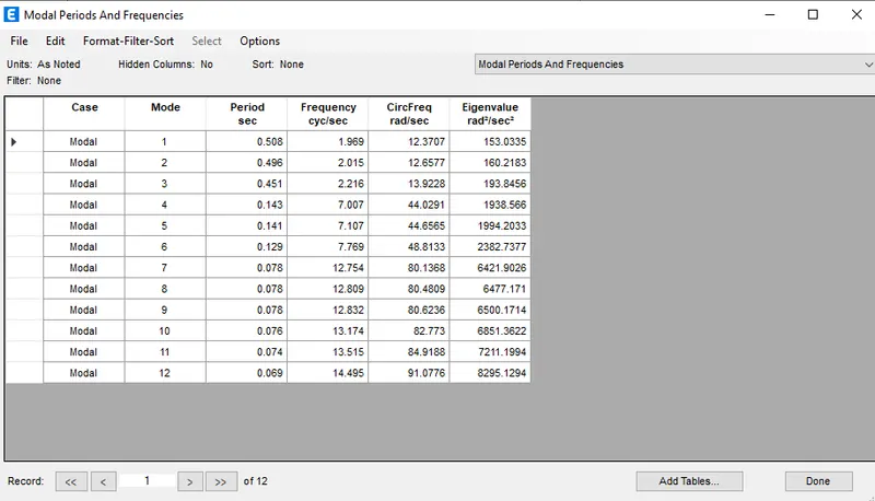
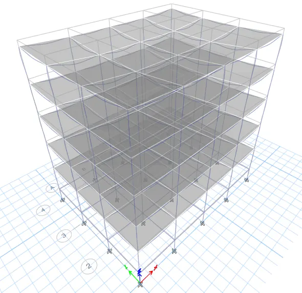
Building B:
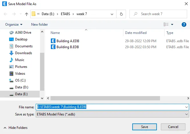
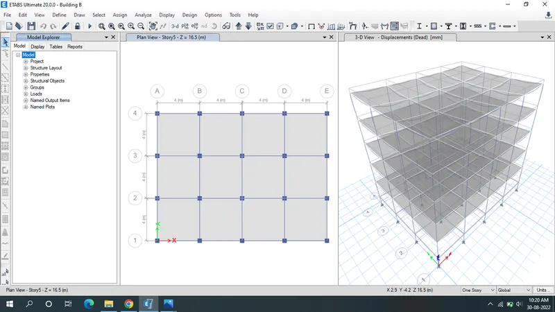
- Go to file menu & save the Building A as Building B.
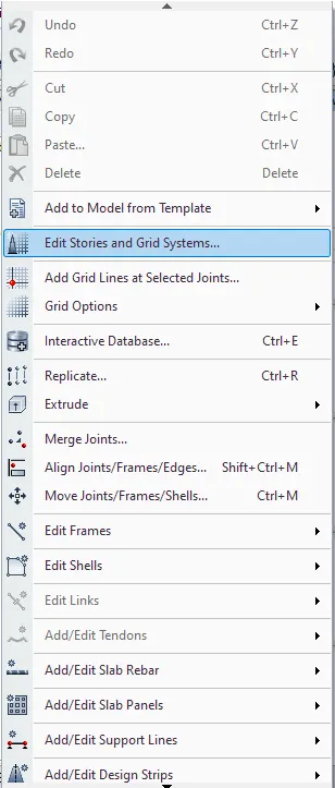
- Building B should be designed for 5 story with same column & beam size as Building A model go to edit & select edit stories & gride system.
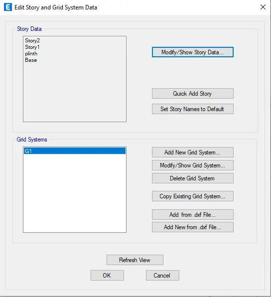
- Click on Modify/show story data already 2 story is there by right clicking the arrow given in top row add 3 more story and do the settings accordingly and press ok.
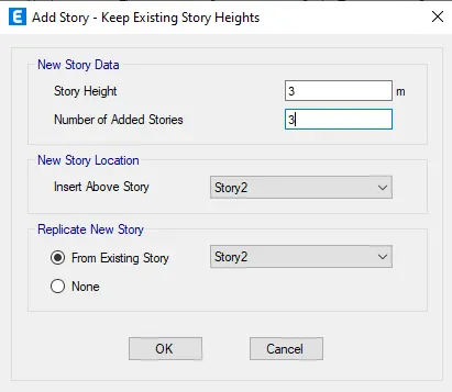
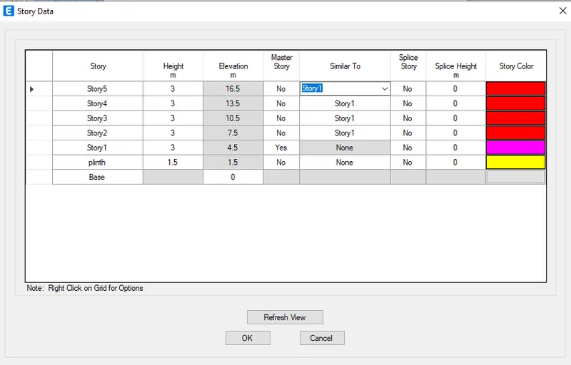
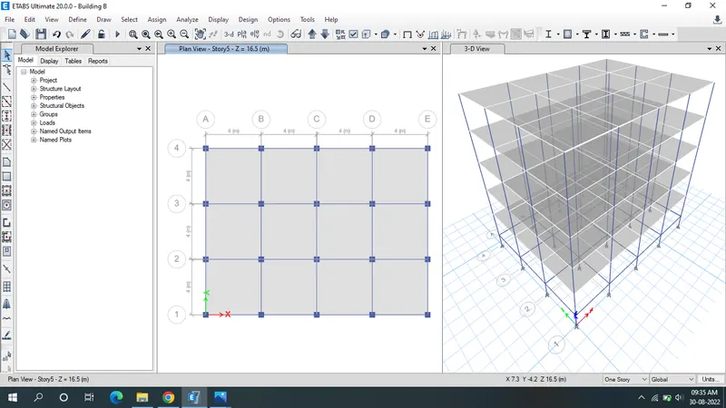
- check the wall load are assigned to the beams & live load are assigned to the floor
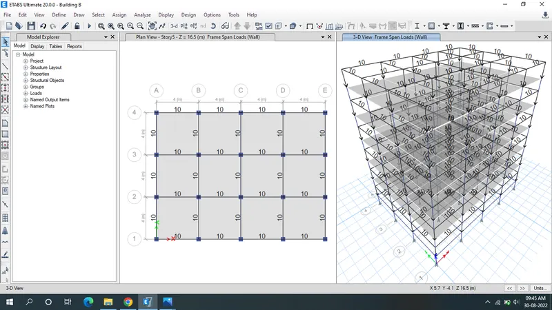
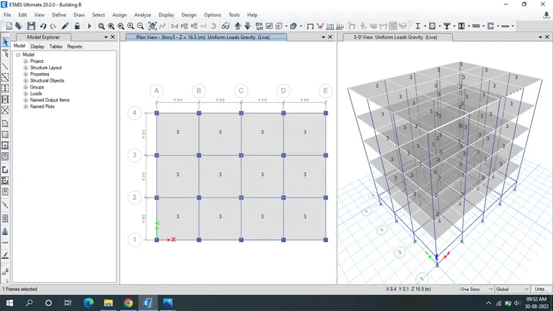
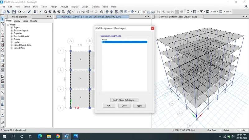
- select the slab.
- Click the "Assign" select the shell.
- Then select the "Diaphagms".
- Click the D1 & apply,ok
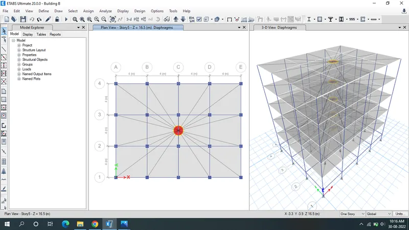
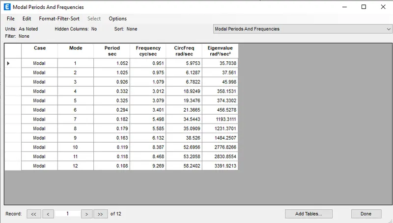
- Click the run Analysis.
- Result will shown below.
Building C:
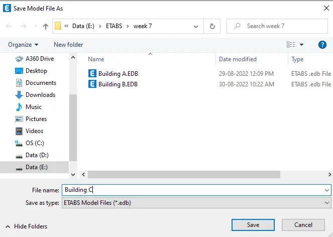
- Go to file menu & save the Building B as Building C.
- The Stories is same as that of building B but the column size is different 550X300 mm.
- Go to define tab select section properties and in that frame section s and modify the column 400X400 mm to 550X300mm and refresh the view.
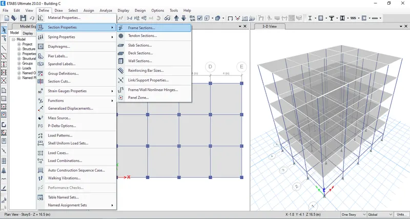
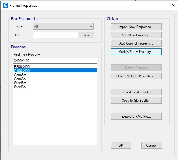
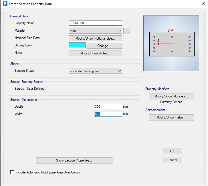
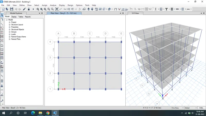
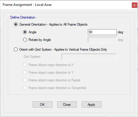
- In the above view the column as oriented in y direction but we need it in x direction
- Go to select tab in that select properties and select frame section and select column 550 X 300
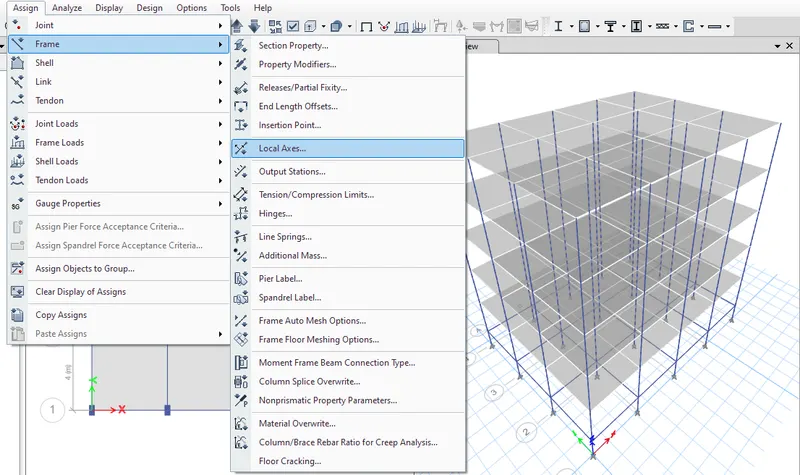
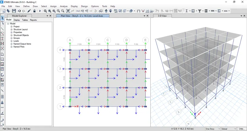
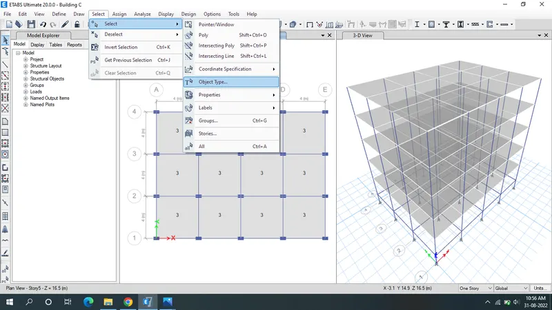
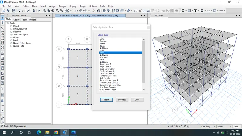
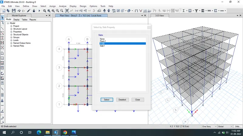
- To create the diaphragm to the shell go to select in that select object type and in that select floors and click select and press close.
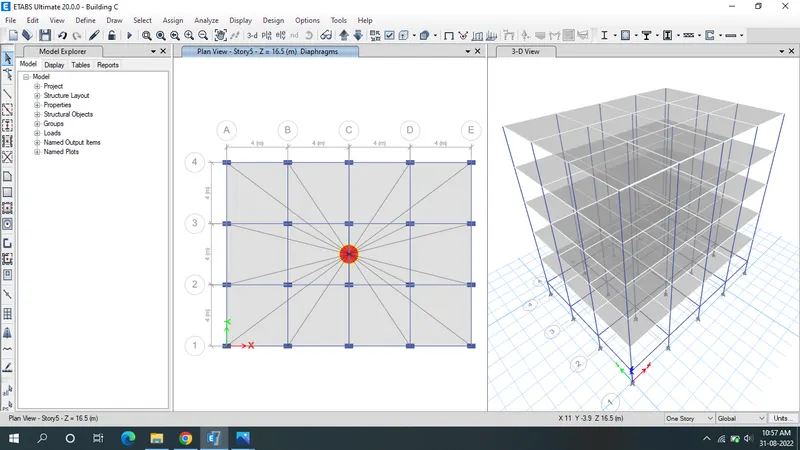
- Click the run Analysis.
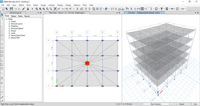
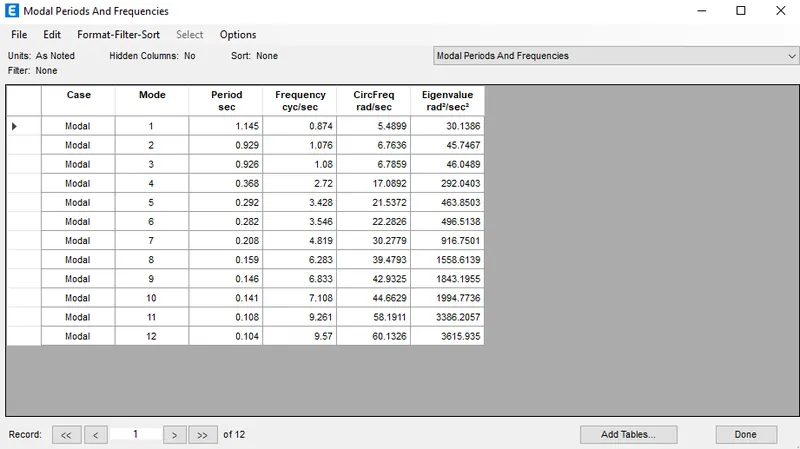
- Result will shown below.
Building D:
- Go to file menu & save the Building C as Building D.
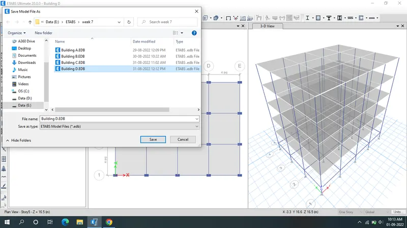
- The Stories is same as that of building C but the column size is different 300X550 mm
- Go to select tab in that select properties and select frame section and select column 550X300.
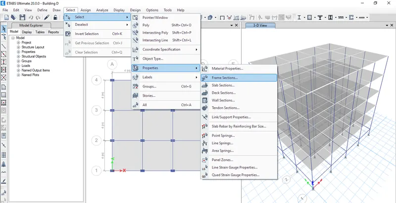
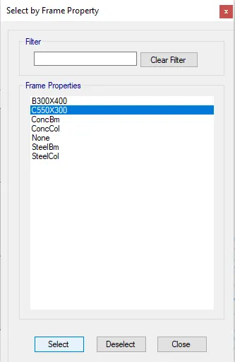
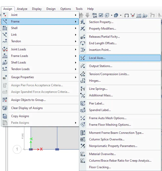
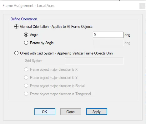
- Go to Asiign tab in tha select frame and local axies and keep the angle as 0 degree
- The column will rotate towards y direction

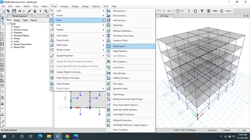
- Go to assign tab select shell in that select diaphragms and select D1 and click ok
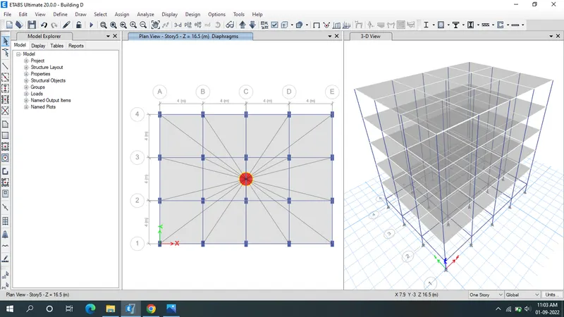
- Click the run Analysis.
- Result will shown below.
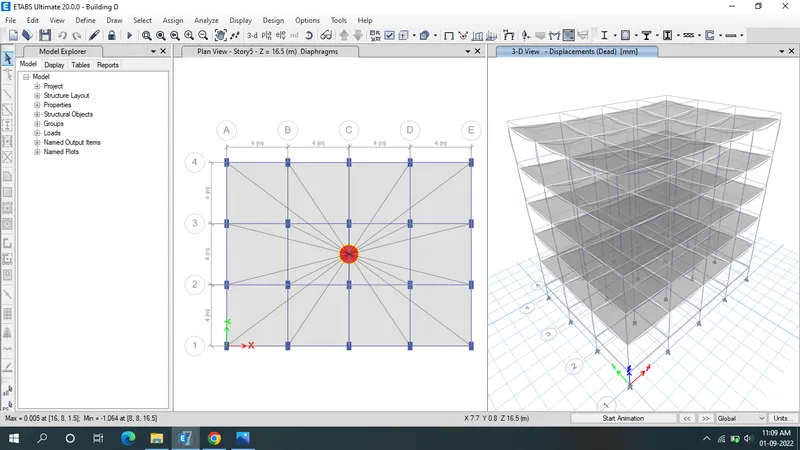
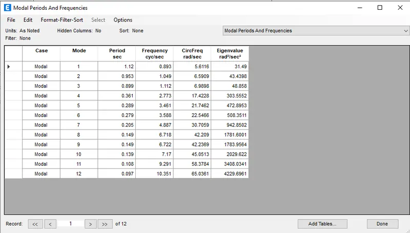
Building E:
- Go to file menu & save the Building D as Building E.
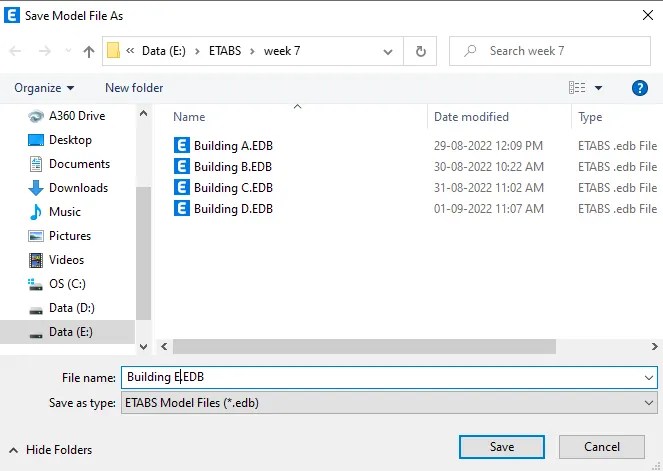
- Building E model sould be designed for 10 story
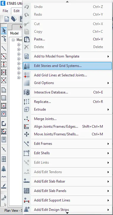
- Go to edit tab select Edit stories and grid system
- Click on Modify/show story data already 5 story is there by right clicking the arrow given in top row add 5 more story and do the settings accordingly and press ok
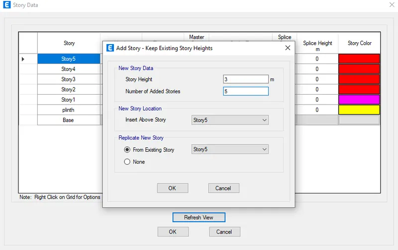
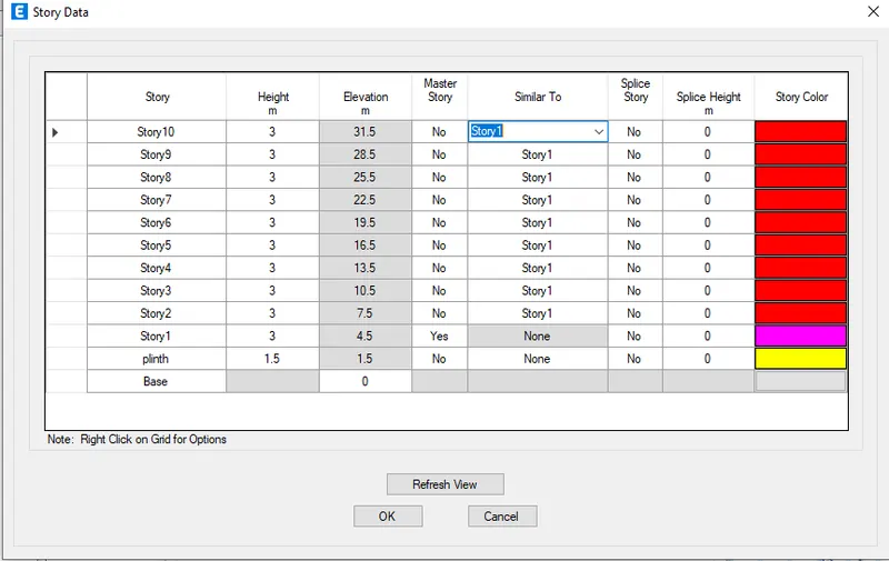
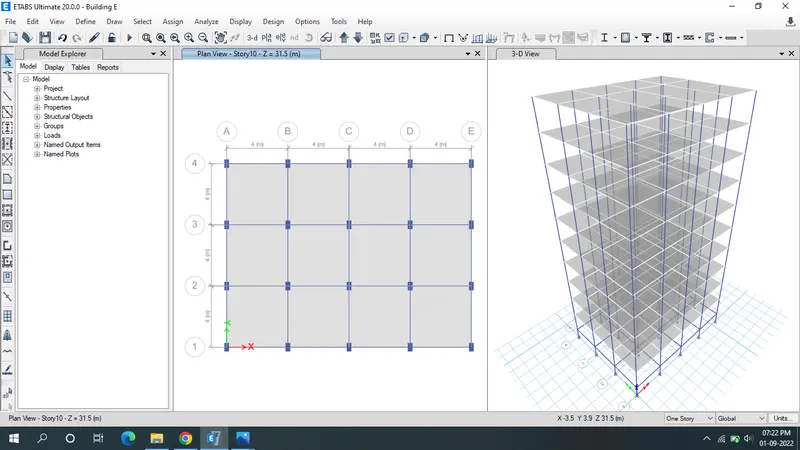
- Now check whether the brickwall load assigned to beams and live load is aasigned to all the floors
- Click on display frame load assigned and check whether the load is assigned by clicking on apply
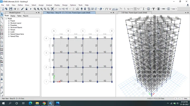
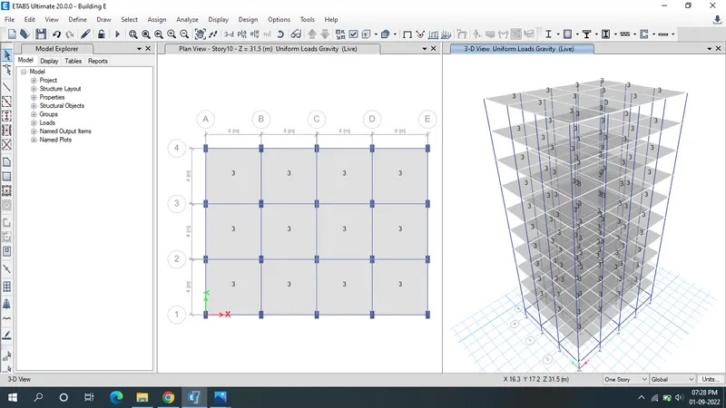
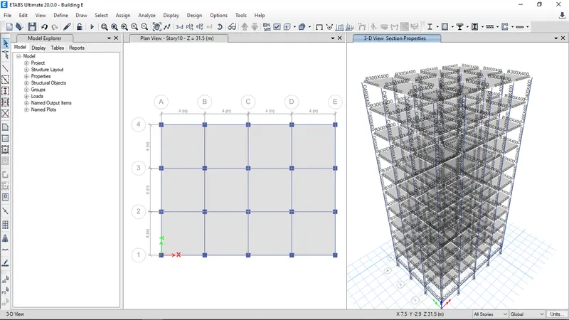
- There are 2 different size columns i.e, for upper 5 story the column size is 400X400 mm and for the bottom 5 stories the column size is 600X600 mm.
- Go to define tab select section properties and in that frame section s and modify the column 550X300 mm to 600X600mm and add other column as 400X400 mm and refresh the view.
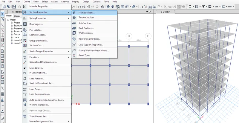
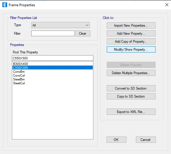

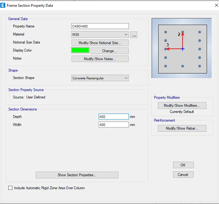
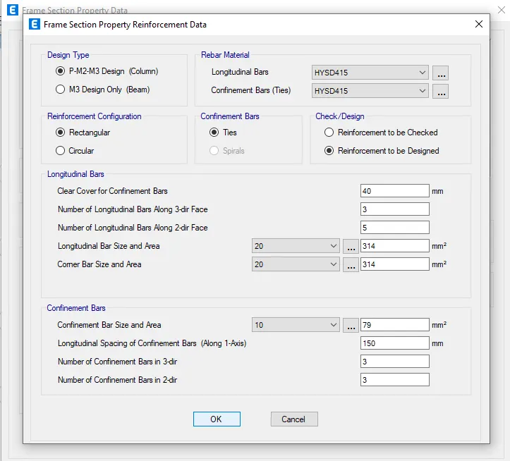
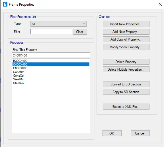
- As per model created all the columns in all the story is 600 X 600 mm, now we need to change the column size as 400 X 400 mm from story 6 to story 10.
- We have hide beams and slabs, Click on set display option and select beams and floors so that they will hide.
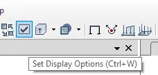
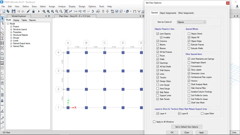
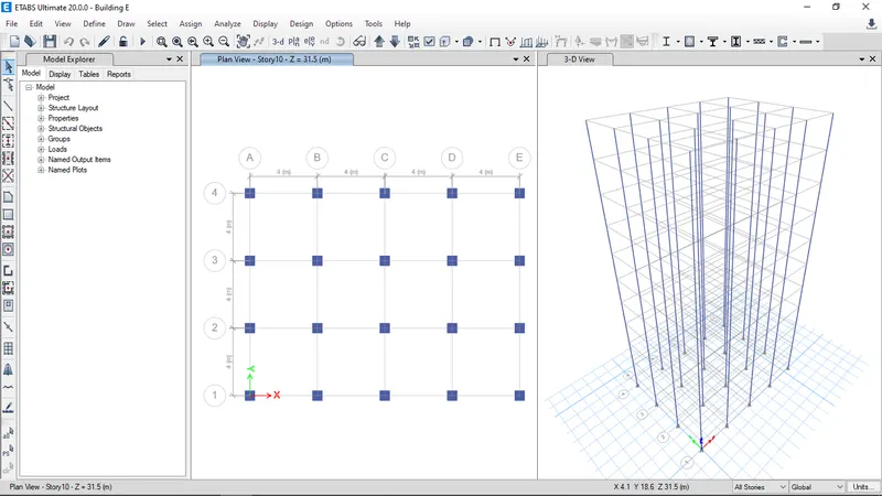
- Go to view tab and select set building view limits give the inputs as story 6 to story 10 and click on ok
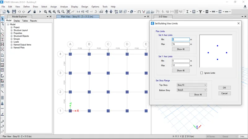
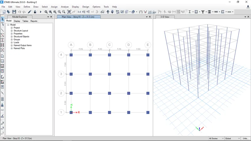
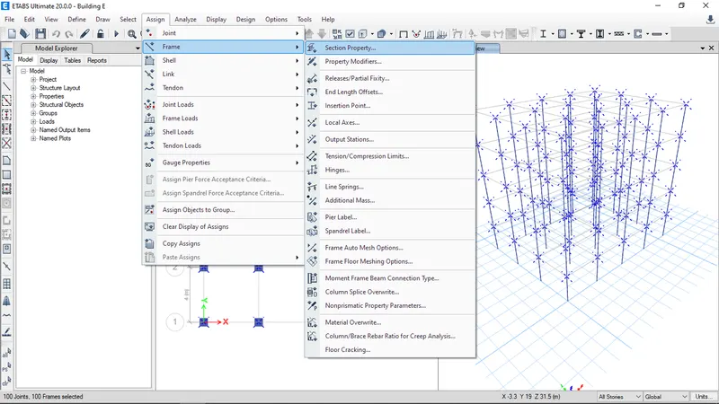
- Select the columns go to assign in that select frame and section properties
- Select column 400X400 mm and apply
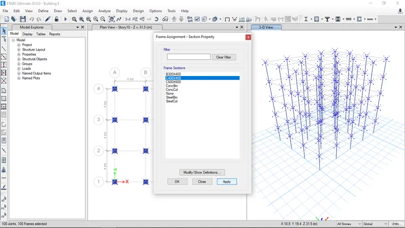
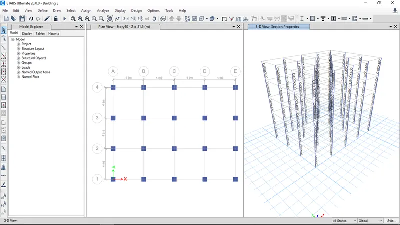
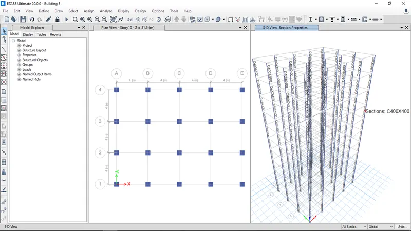
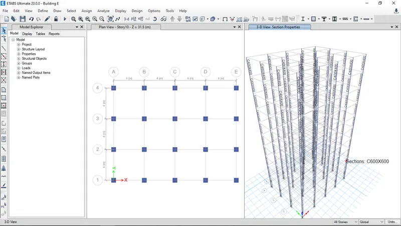
- Click on set display option and select beams and floors so that they will unhide
- To create the diaphragm to the shell go to select in that select object type and in that select floors and click select and press close.
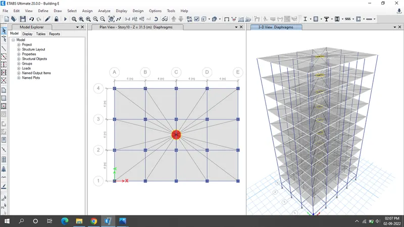
- Click the run Analysis.
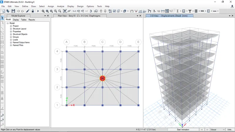
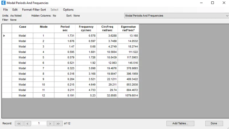
- Result will shown below.
Building F:
- Go to file menu & save the Building E as Building F.
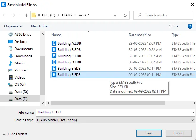
- Story of Building F is as same as Building E model
- But all the story have same column size as 600X600mm so wherver change the column size from story 6 to story 10
- We have hide beams and slabs, Click on set display option and select beams and floors so that they will hide.
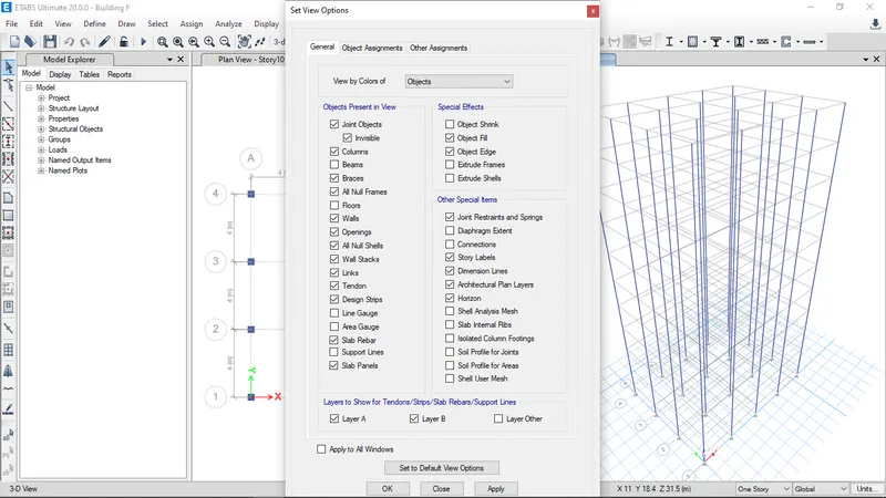
- Now beams and slabs are not visible
- Go to view tab and select set building view limits give the inputs as story 6 to story 10 and click on ok.
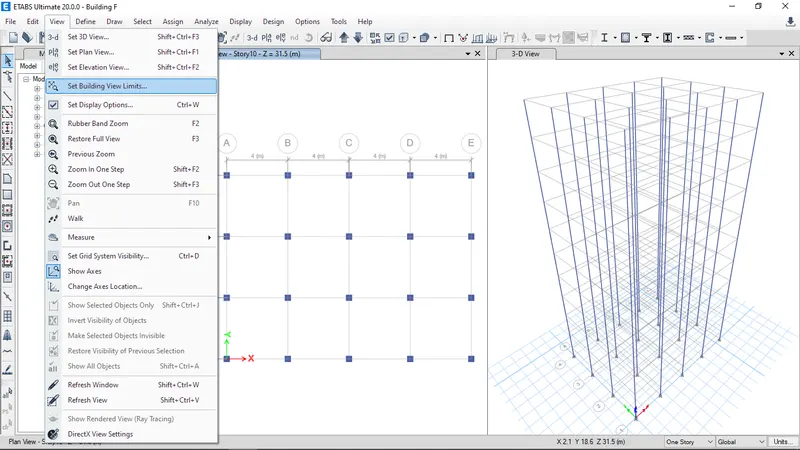
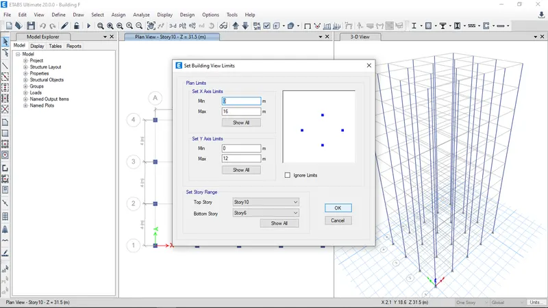
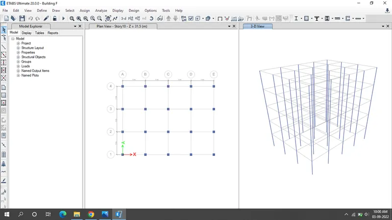
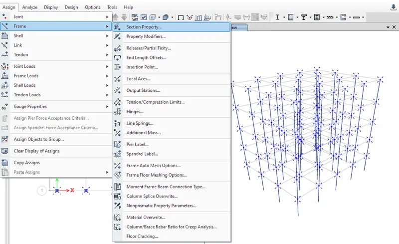
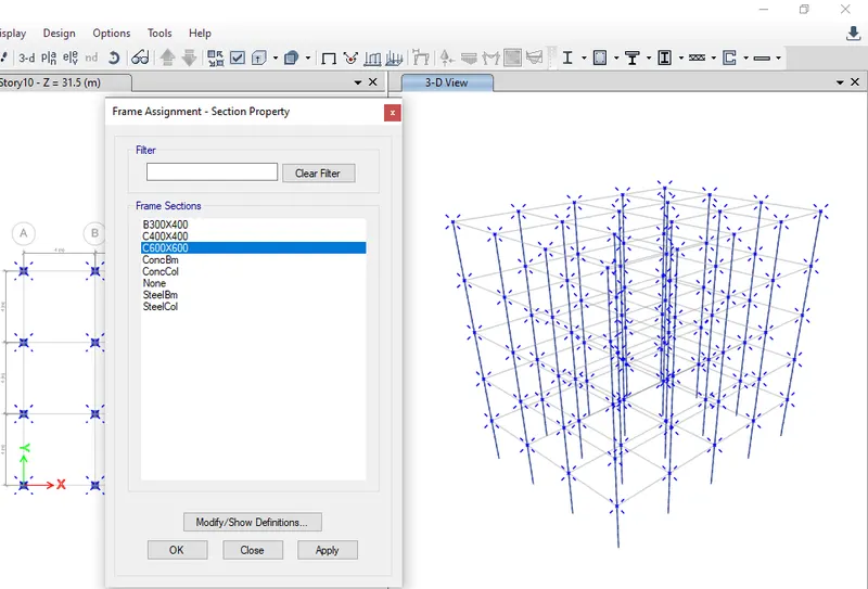
- Select the columns go to assign in that select frame and section properties
- Select column 600X600mm and apply.
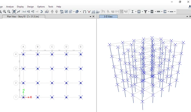
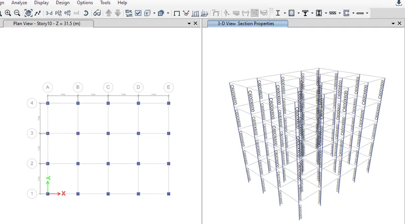
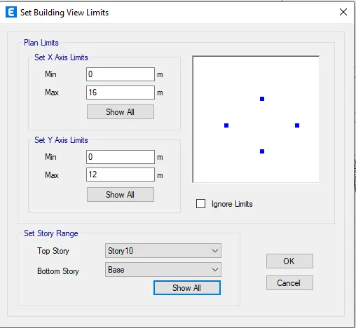
- Go to view tab and select set building view limits give the inputs as base to story 10 and click on ok.
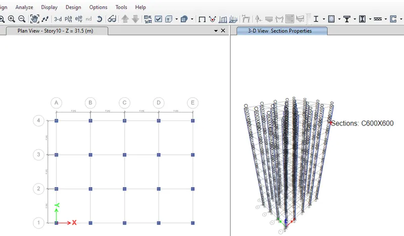
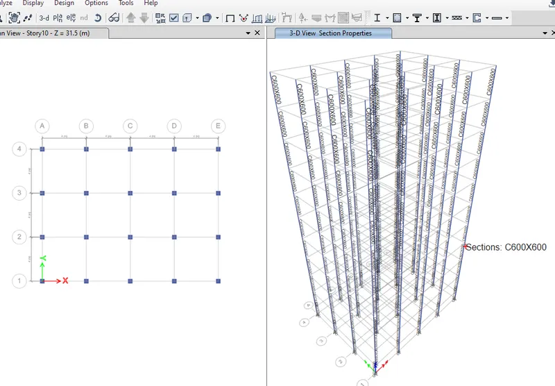
- Click on set display option and select beams and floors so that they will unhide.
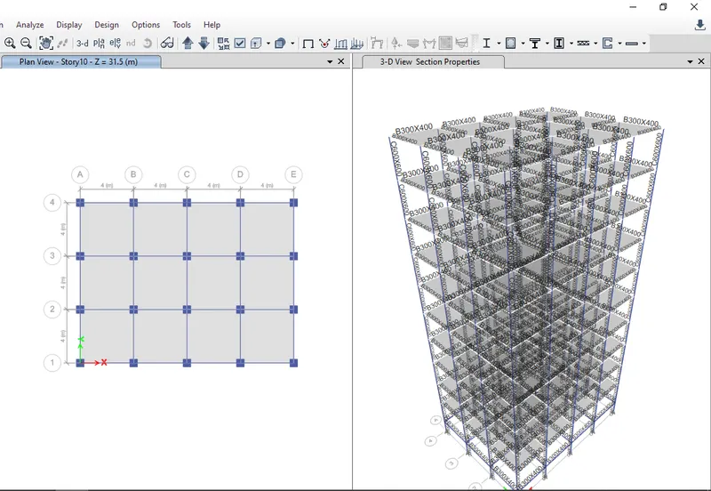
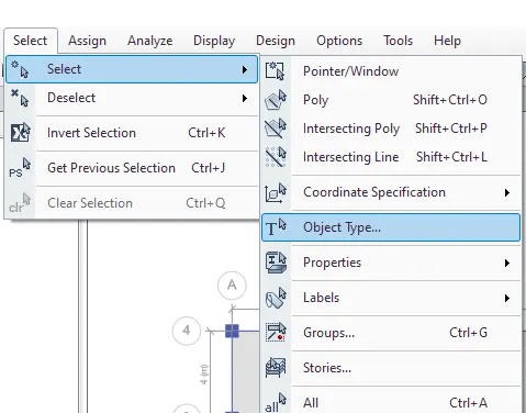
- To create the diaphragm to the shell go to select in that select object type and in that select floors and click select and press close.
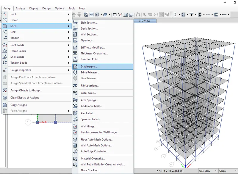
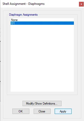
- Go to assign tab select shell in that select diaphragms and select D1 and click ok.
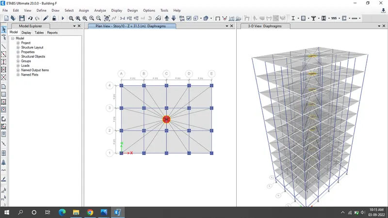
- Click the run Analysis.
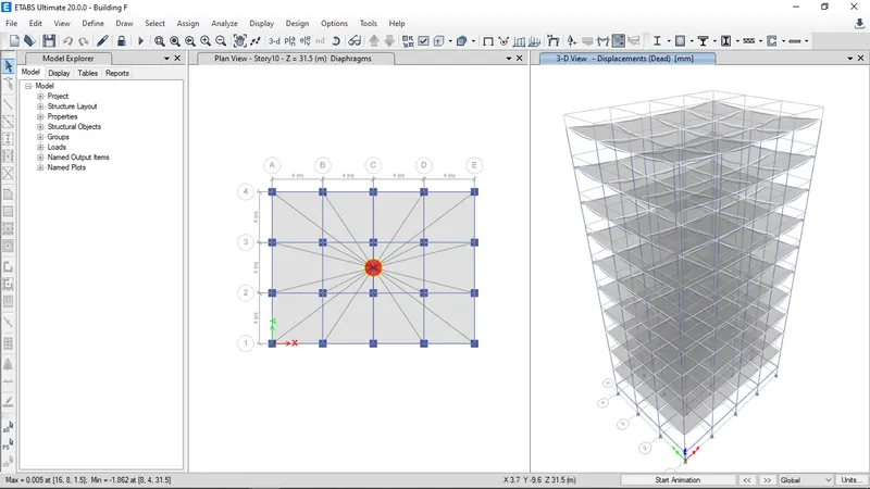
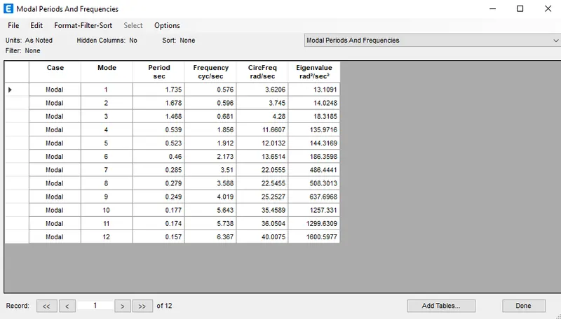
- Result will shown below.
Building G:
- Go to file menu & save the Building F as Building G.
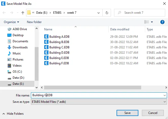
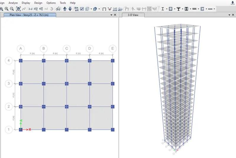
- Building G model sould be designed for 25 story
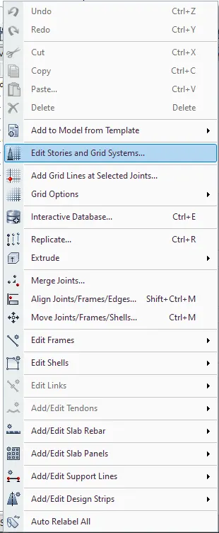
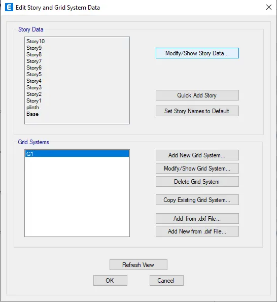
- Go to edit tab select Edit stories and grid system
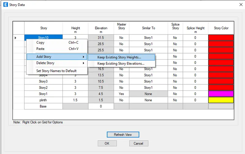
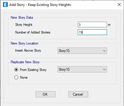
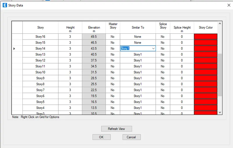
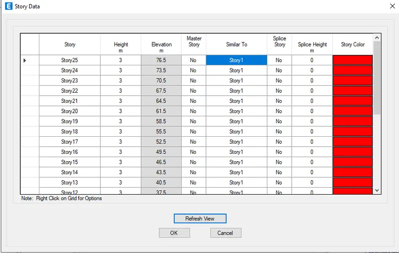
- Click on Modify/show story data already 10 story is there by right clicking the arrow given in top row add 15 more story and do the settings accordingly and press ok.
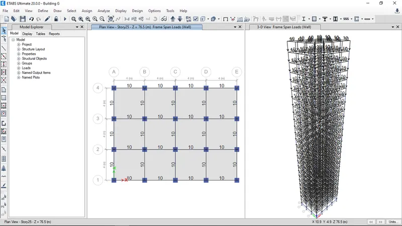
- Now check whether the brickwall load assigned to beams and live load is aasigned to all the floors
- Click on display frame load assigned and check whether the load is assigned by clicking on apply
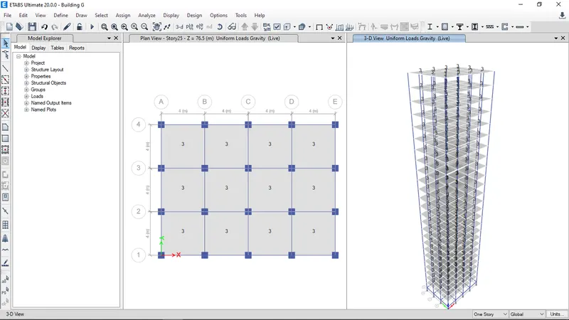
- There are 3 different size columns i.e, for upper 5 story the column size is 400X400mm, for the middle 10 stories the column size is 600X600mm and for the bottom 5 stories the column size is 800X800 mm
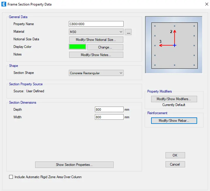
- In the model column 400X400mm and column 600 X 600 mm is already created now we need to create only column 800X800mm.
- Go to define tab select section properties and add new property as column 800X800mm.
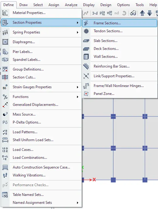
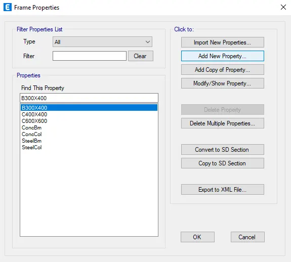
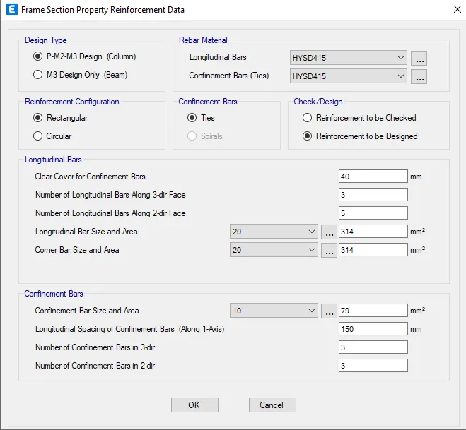
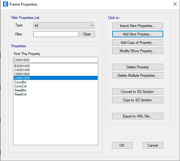
- As per model created all the columns in all the story is 600X600mm, now we need to change the column size as 400X400mm from story 21 to story 25, Column size as 600X600mm from story 11 to 20 and column size as 800X800mm from base to story 10.
- We have hide beams and slabs, Click on set display option and select beams and floors so that they will hide.
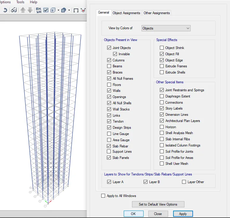
- Now beams and slabs are not visible
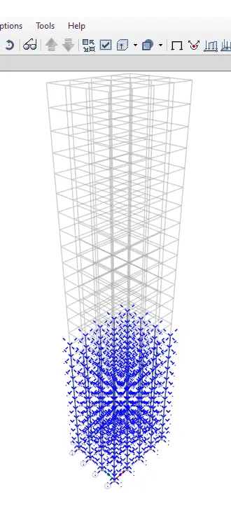
- Go to view tab and select set building view limits give the inputs as base to story 10 and click on ok.
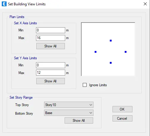
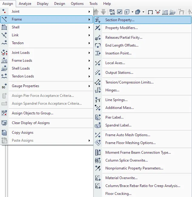
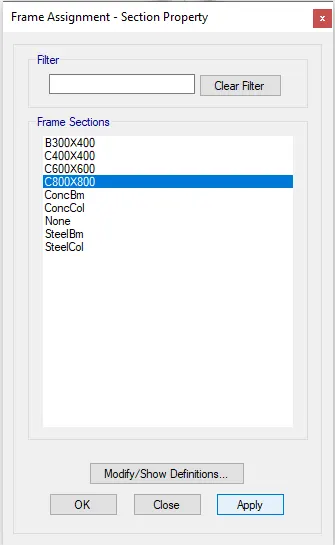
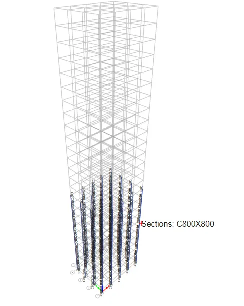
- Select the columns go to assign in that select frame and section properties
- Select column 800X800mm and apply
- Go to view tab and select set building view limits give the inputs as story 11 to story 20 and click on ok.
- The column size is already column 600X600mm so need to change.
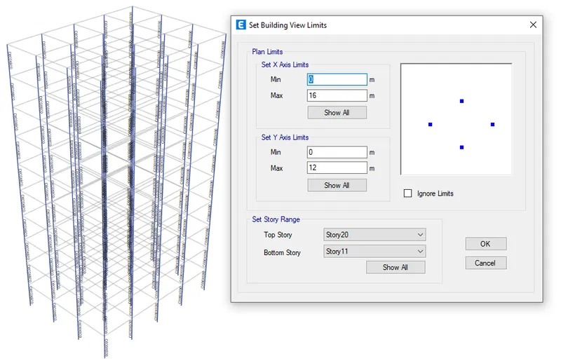
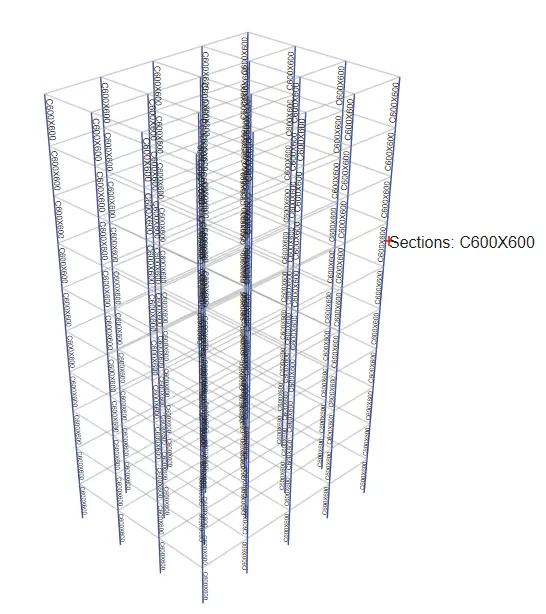
- Go to view tab and select set building view limits give the inputs as story 21 to story 25 and click on ok.
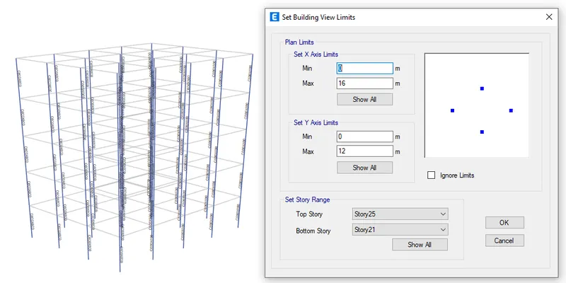
- Select the columns go to assign in that select frame and section properties.
- Select column 400X400mm and apply.
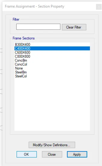
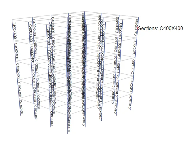
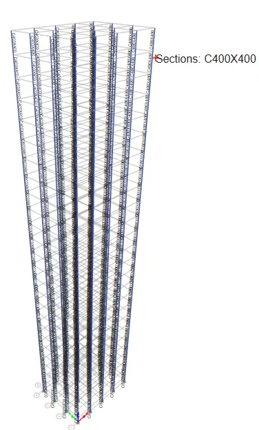
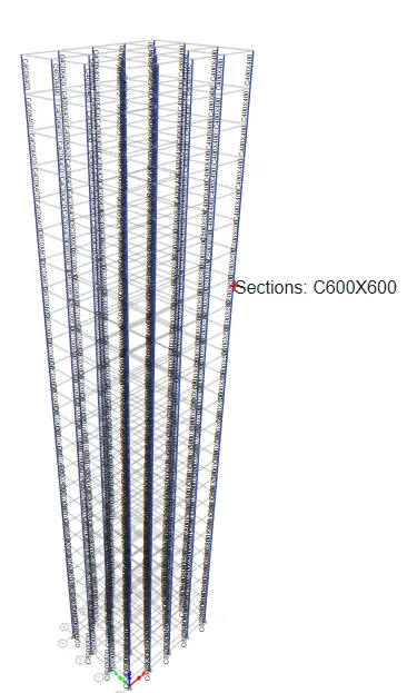
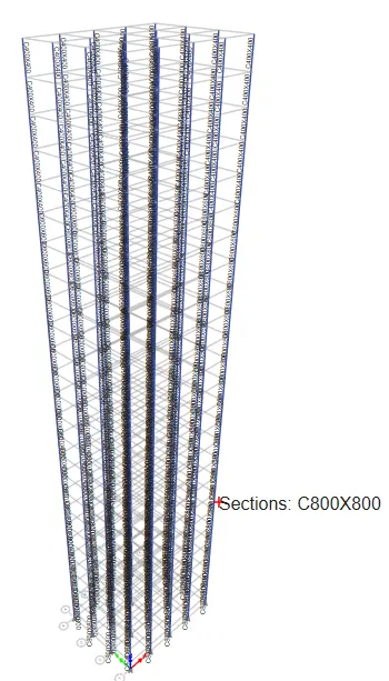
- Click on set display option and select beams and floors so that they will unhide.
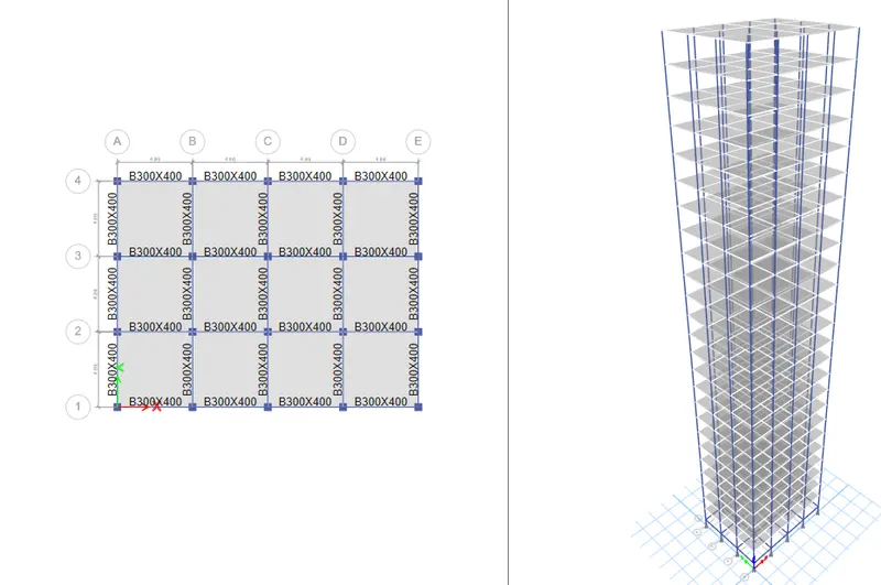
- To create the diaphragm to the shell go to select in that select object type and in that select floors and click select and press close.
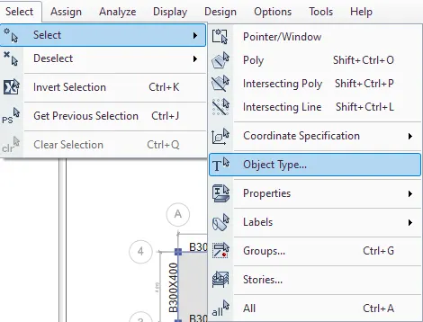
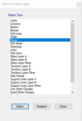
- Go to assign tab select shell in that select diaphragms and select D1 and click ok.
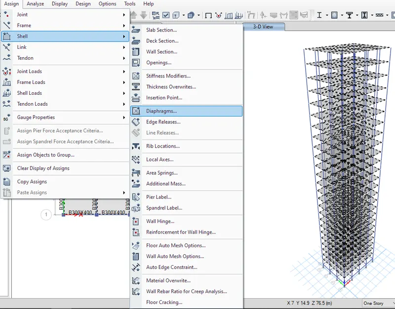
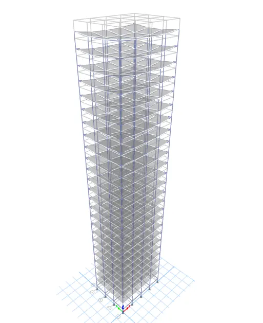
- Click the run Analysis.
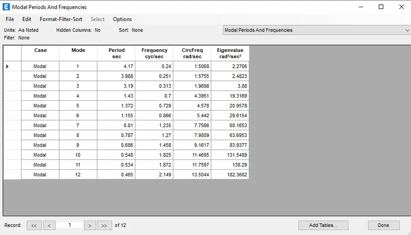
- Result will shown below.
Building H:
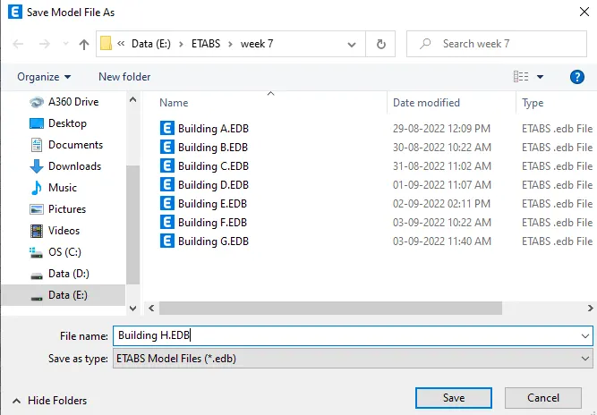
- Go to file menu & save the Building G as Building H.
- Story of Building H is as same as Building G model
- But all the story have same column size as 800X800mm so wehave change the column size from story 11 to story 25
- We have hide beams and slabs, Click on set display option and select beams and floors so that they will hide.
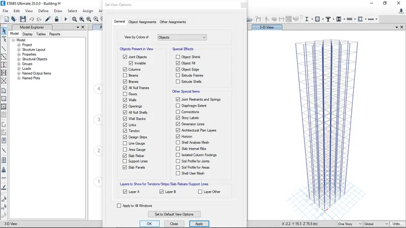
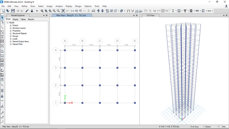
- Go to view tab and select set building view limits give the inputs as story 11 to story 25 and click on ok.
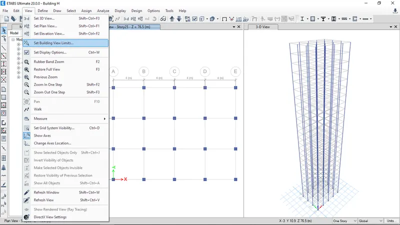
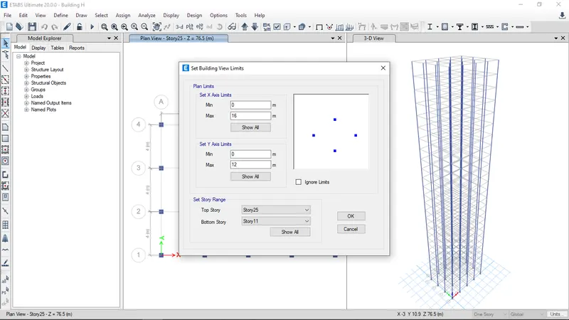
- Select the columns go to assign in that select frame and section properties
- Select column 800X800mm and apply.
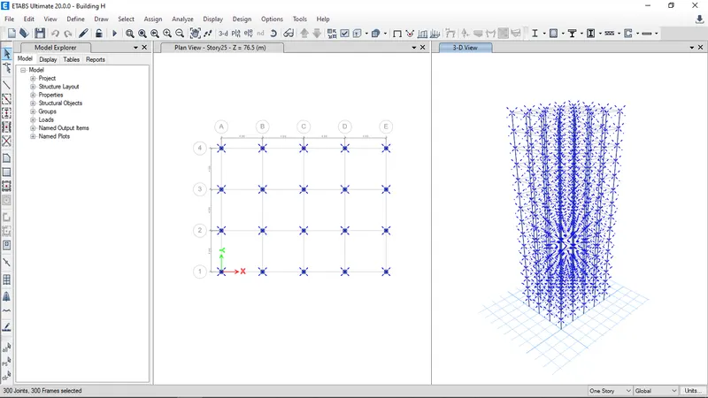
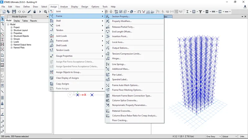
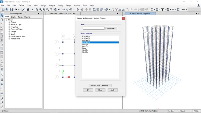
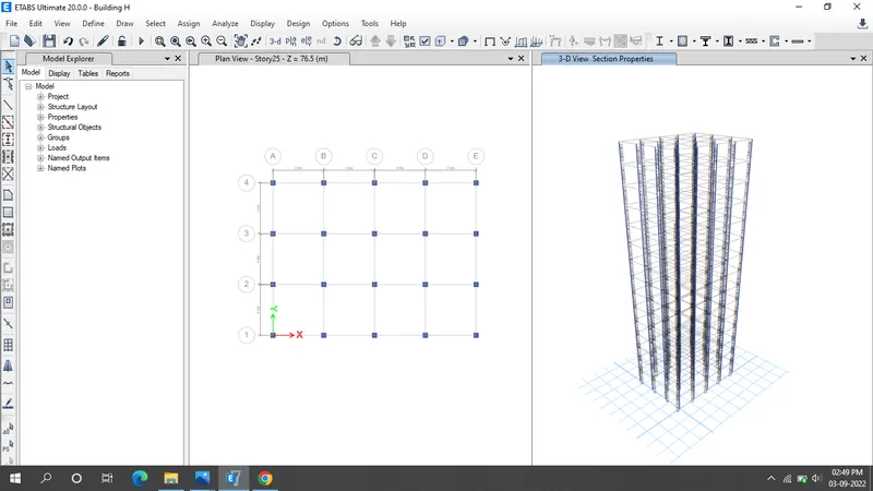
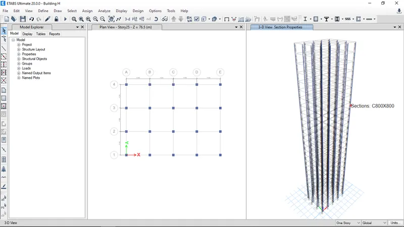
- Click on set display option and select beams and floors so that they will unhide.
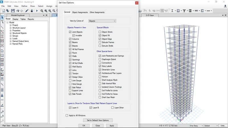
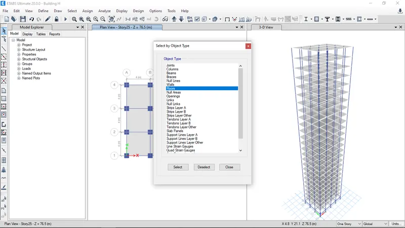
- To create the diaphragm to the shell go to select in that select object type and in that select floors and click select and press close.
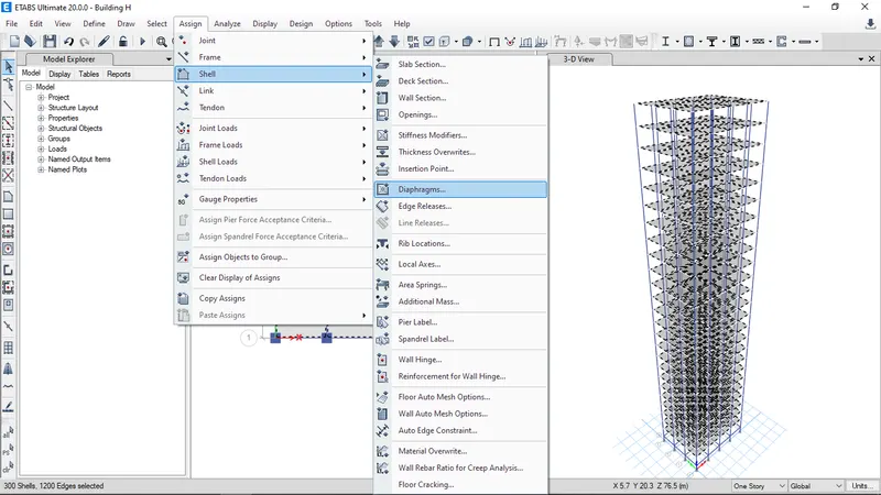
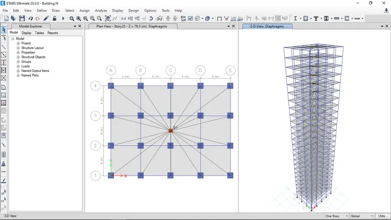
- Click the run Analysis.
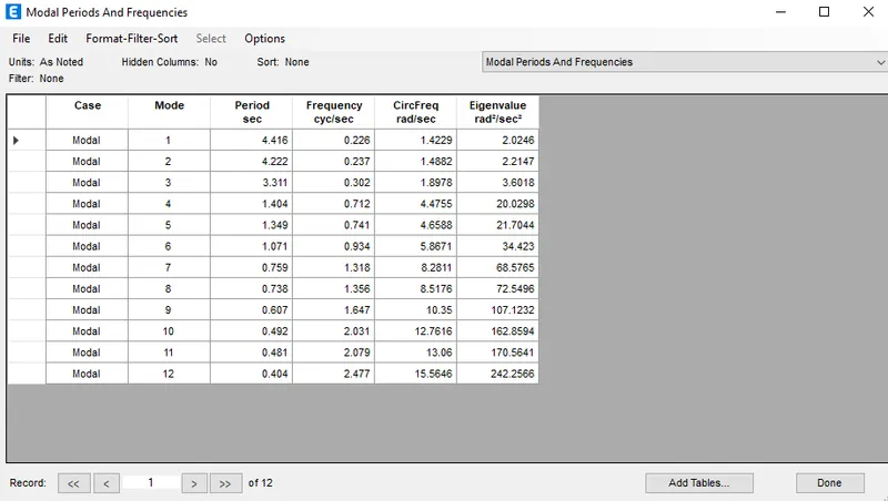
- Result will shown below.
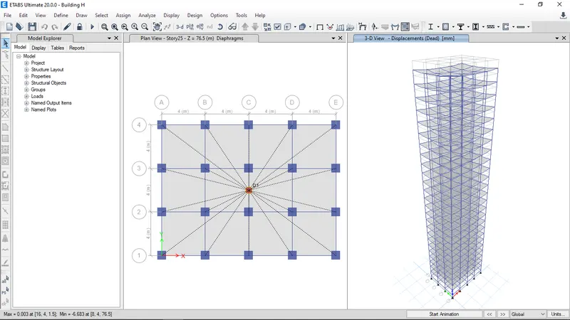
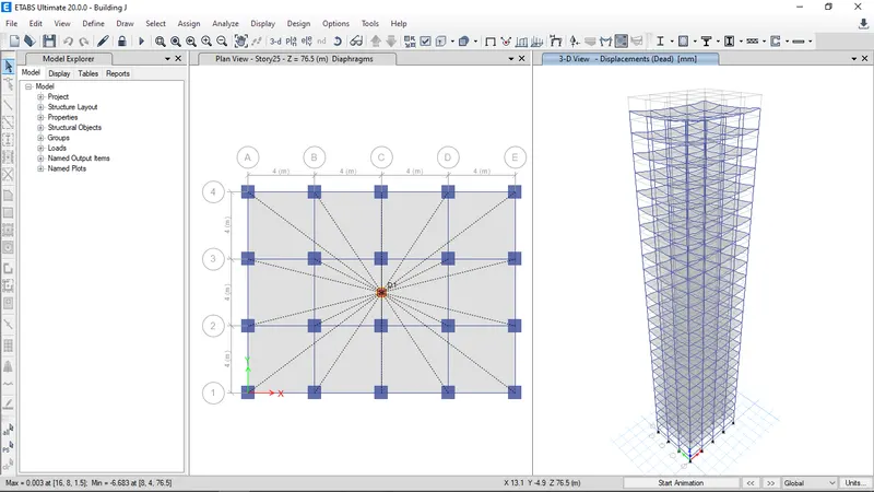
Building J:
- Go to file menu & save the Building H as Building J.
- Story of Building J is as same as Building H model ,Even column sizes are same
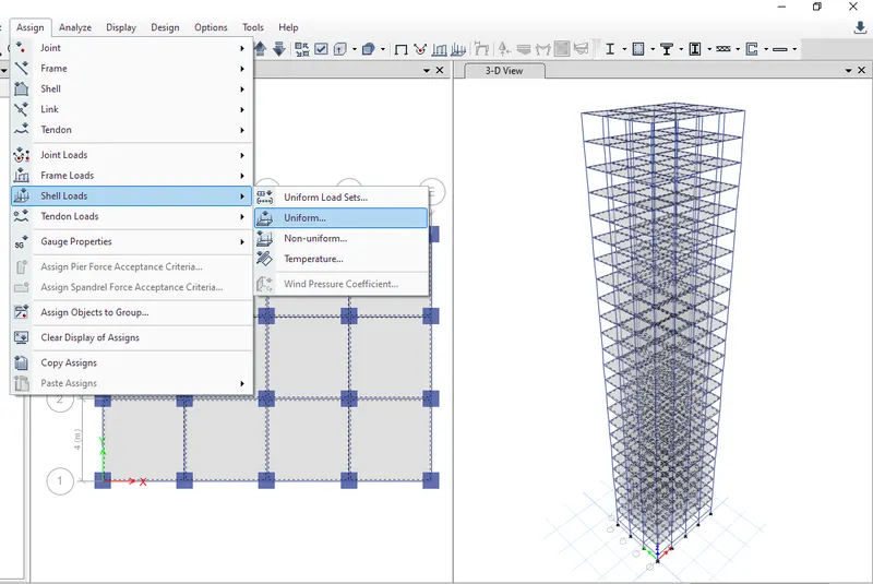
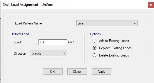
- But the live load acting on the slab is 10% more than the Building H i.e, 3.3 kN/m^2
- Go to select in that select object type and in that select floors and click select and press close.
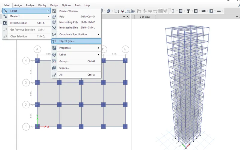
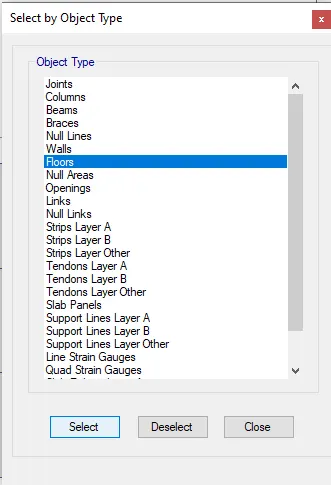
- Go to assign in that select shell load and select uniform load.
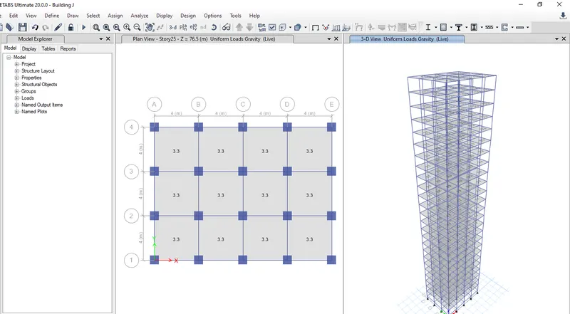
- To create the diaphragm to the shell go to select in that select object type and in that select floors and click select and press close.
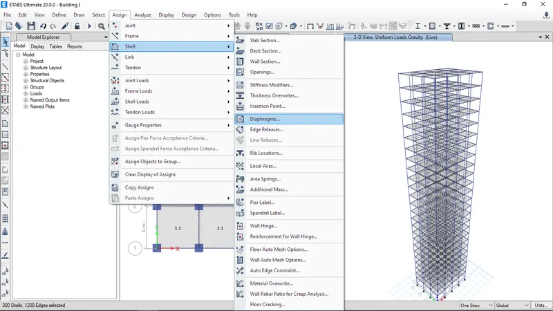
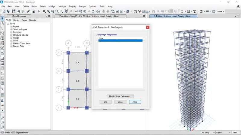
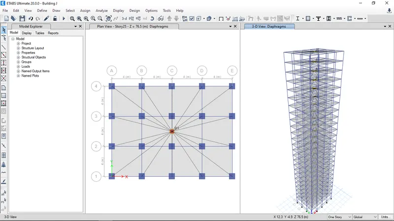
- Go to assign tab select shell in that select diaphragms and select D1 and click ok.
- Click the run Analysis.
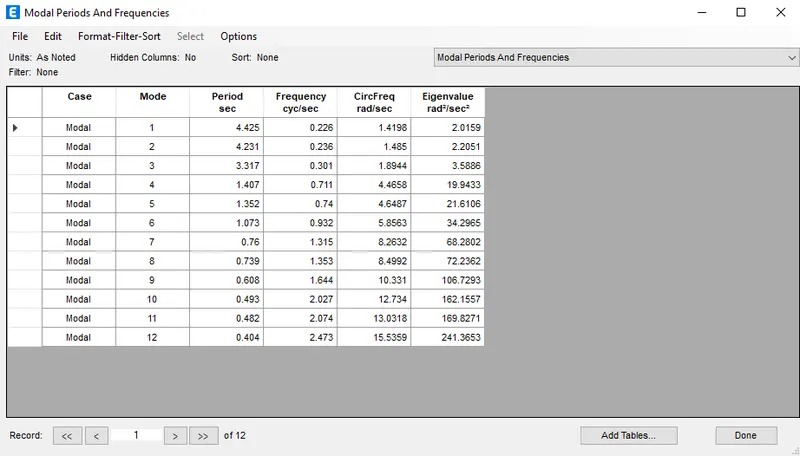
- Result will shown below.
Building K:
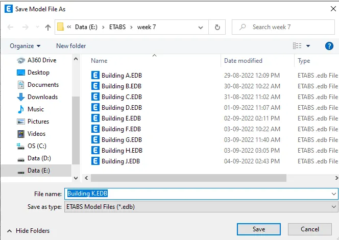
- Go to file menu & save the Building J as Building K.
- Story of Building K is as same as Building J model ,Even column sizes are same
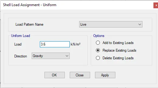
- But the live load acting on the slab is 20% more than the Building H i.e, 3.6 kN/m^2
- Go to select in that select object type and in that select floors and click select and press close.
- Go to assign in that select shell load and select uniform load.
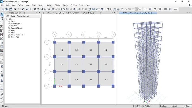
- To create the diaphragm to the shell go to select in that select object type and in that select floors and click select and press close.
- Go to assign in that select shell load and select uniform load.
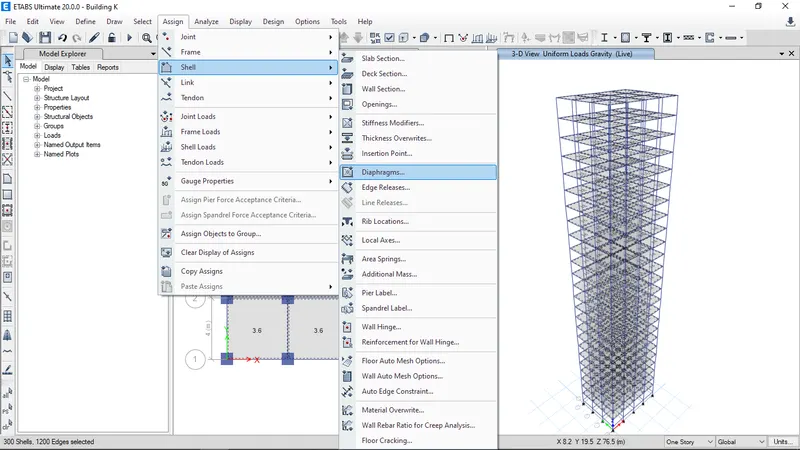
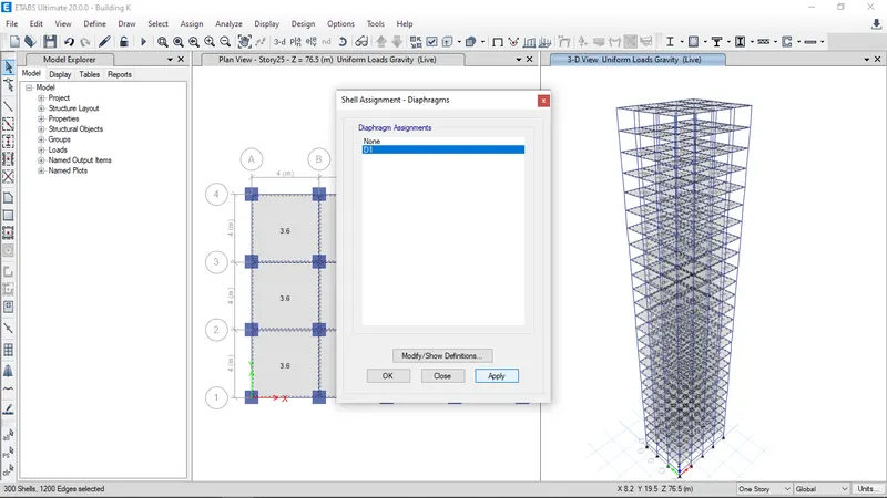
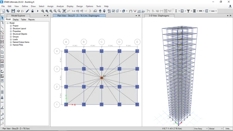
- Click the run Analysis.
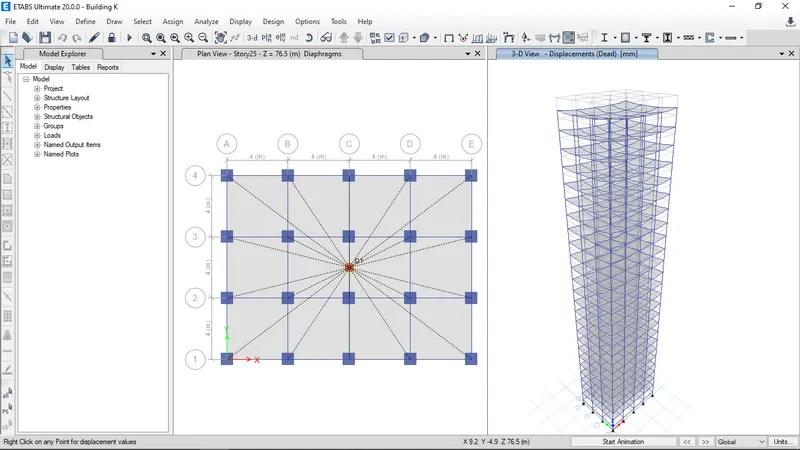
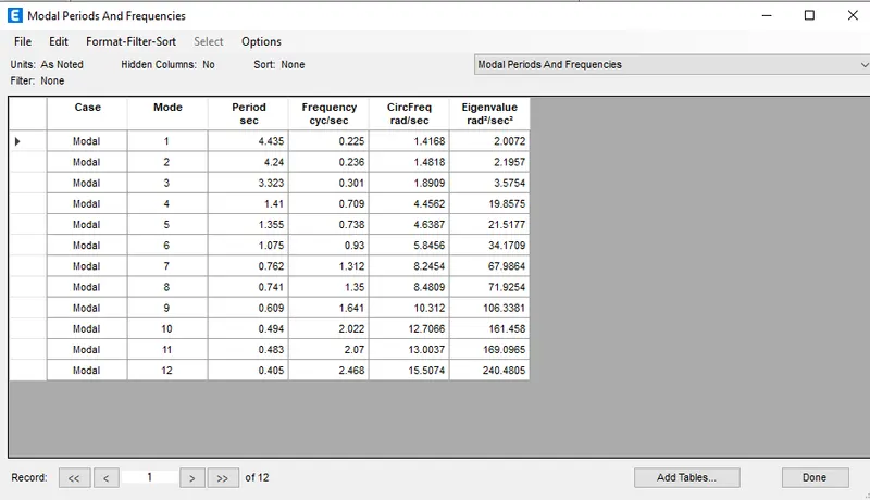
- Result will shown below.
Result:
1.Effect of stiffness on T: Compare fundamental natural periods of buildings E & F as well as G & H. Why is there a marginal or significant difference in the fundamental natural periods?
| Criteria | Building Model | Analysis Result |
| Effect of stiffness on Time period |
Building E (10 story with varying column size) Building F (10 story with uniform column size) |
1.731s 1.735s |
| Effect of stiffness on Time period |
Building G (25 story with varying column size) Building H (25 story with uniform column size) |
4.17s 4.416s |
In 10 story building there is no significant difference in the fundamental natural periods in the mode 1
In 25 story building the varying column sizes are more stable than uniform colum sizes because in uniform column size buiding the excess mass is lumped at the top story of the building so the mass directly proportional to the lateral load acting on the building that induces more lateral displacement of the building leading to greater time period
2.Effect of mass on T: Compare fundamental natural periods of buildings H, J and K. Have the buildings become more flexible or stiff due to change in mass?
| Criteria | Building model | Analysis Result |
| Effect of mass on time period |
Building H (25 story with 3KN/sq.m imposed load) Building J (25 story with 3.3KN/sq.m imposed load) Building K (25 story with 3.6KN/sq.m imposed load) |
4.416s 4.425s 4.435s |
- There is a difference in time period but not so significant variations in the time period because the imposed load acting on all the floors are same. If there is only variation in the top floor of the building then they are significant.
- Mass is directly proportion to the lateral displacement, so the time period of the building is increased
3.Effect of Building Height on T: How does the fundamental natural periods of Buildings A, B, F and H change with change in building height?
| Criteria | Building model | Analysis Result |
| Effect of Building Height on Time period |
Building A (2 story with uniform column size) Building B (5 story with uniform column size) Building F (10 story with uniform column size) Building G (25 story with uniform column size) |
0.5s
1.036s
1.735s
4.416s |
- As height increase the time period will also increases because height of the building is directly proportion to the time period
4.Effect of Column Orientation on T: How does the fundamental natural periods of Buildings B, C and D change with change in column orientation?
| Criteria | Building model | Analysis Result |
| Effect of mass on Time period |
Building B (All floor column size is 400X400) Building C (All floor column size is 550X300 oriented in X-direction) Building D (All floor column size is 300X550 oriented in Y-direction) |
1.036s
1.145s
1.2s |
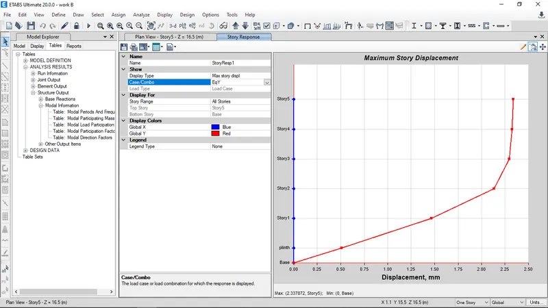
Building B
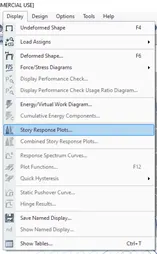
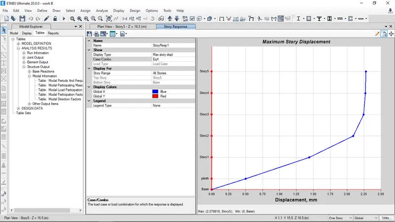
Go to display tap select story response plots.
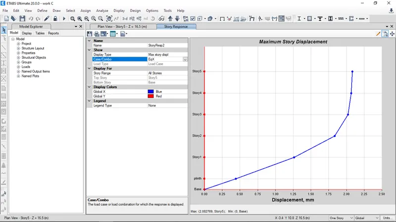
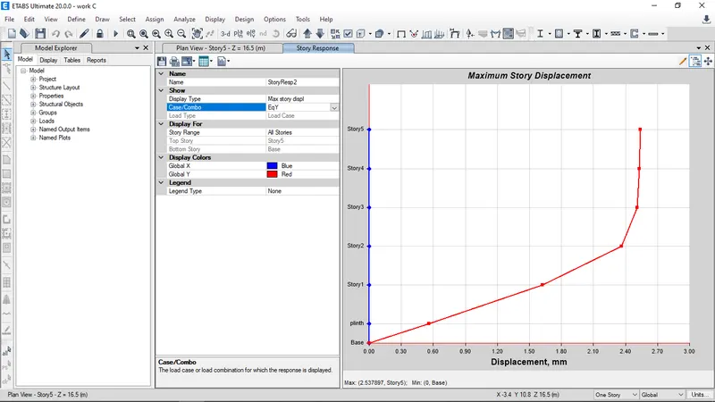
Building C
Go to display tap select story response plots.
Building D
Go to display tap select story response plots.
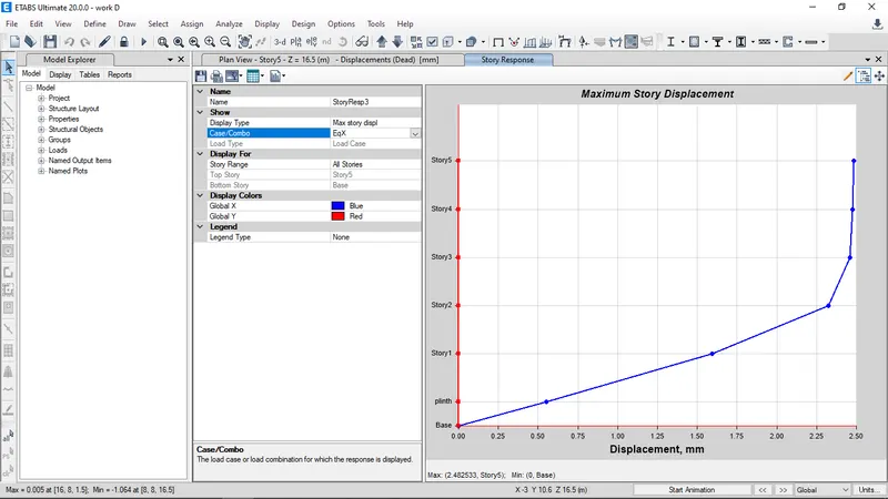
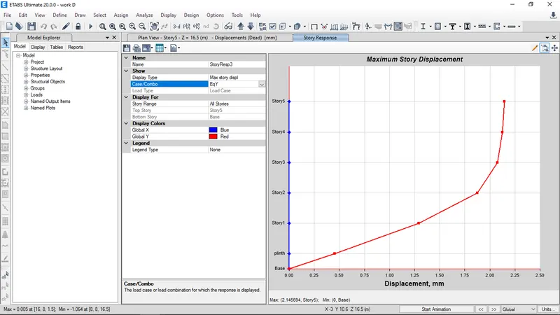
- Effect of column orientation depends on the flexible behaviour of the building.
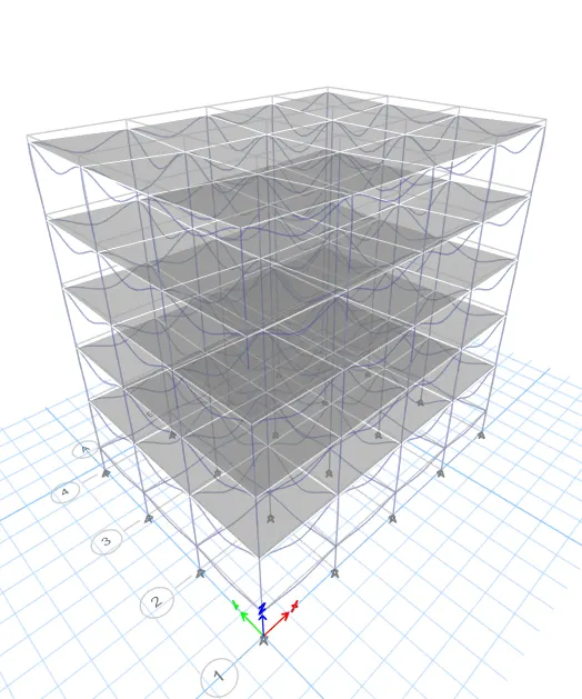
5.Effect of Flexural Stiffness of Structural Elements on mode shapes: Compare fundamental mode shape of Building B in two situations when flexural stiffness of beams relative to that of adjoining columns is very small versus when it is large.
| Criteria | Building model | Case | Analysis Result |
| Effect of Flexual stiffness of structural elements on mode shapes |
Building B |
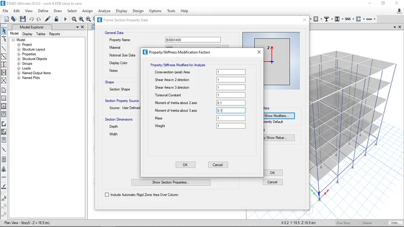
Flexual stiffness beam close to nil(zero inertia) Full flexual stiffness of beams (Regular) |
2.633s
1.036s |
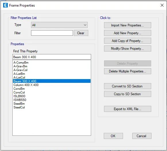
Open Building B model and save as the model
Go to define tab select section properties in that select frame sections select beam 300 X 400 and modify the property
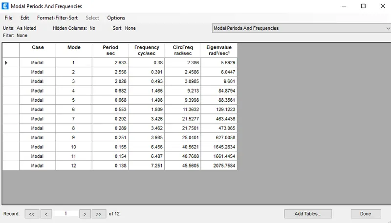
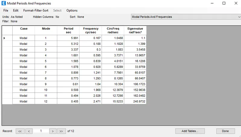
6.Effect of Axial Stiffness of Vertical Members on mode shapes: Compare fundamental mode shape of Building H in two situations when axial cross-sectional area of columns is very small versus when it is large.
| Criteria | Building model | Case | Analysis Result |
| Effect of Axial stiffness of vertical members on mode shapes |
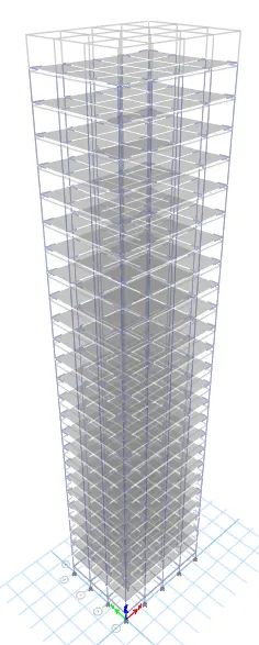
Building H |
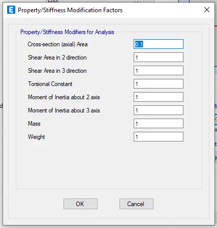
Axial cross section for columns in close to nil(zero inertia) Full Axial cross section for columns (Regular) |
5.991s
4.416s |
Open Building H model and save as the model
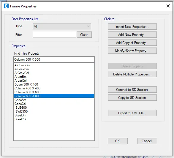
Go to define tab select section properties in that select frame sections select column 800 X 800 and modify the property.
7.Effect of Degree of Fixity at column bases on mode shape: Compare fundamental mode shape of Building B in two situations when base of columns is pinned versus when it is fixed.
| Criteria | Building model | Case | Analysis Result |
| Effect of Degree of fixity at column base on mode shape |
Building B |
Column support pinned (Regular) Column support fixed |
1.036s
0.941s |
- Open Building B model and save as the model
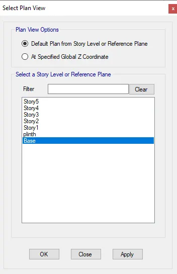
- Select all the joints in the base view
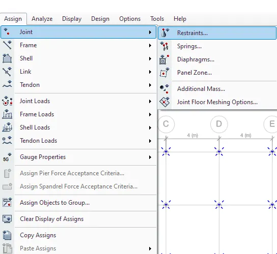
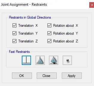
- Go to Assign tab select joints in that restraints and select fixed support