Project 1_Comparative study of different storey buildings for Seismic forces
PROJECT - 1
AIM :-
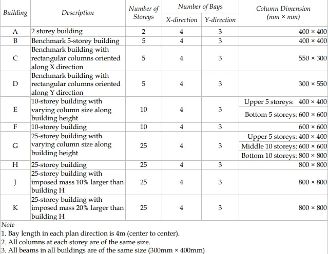
To create a building with following properties and also to compare the time period of different buildings and it's factors influencing time period and other factors of the model.
INTRODUCTION :-
ETABS is an engineering software which can be used for multi-story building analysis and design. Modeling tools and templates, code-based load prescriptions, analysis methods and solution techniques, all coordinate with the grid-like geometry.
PROCEDURE :-
a.For Model A :-
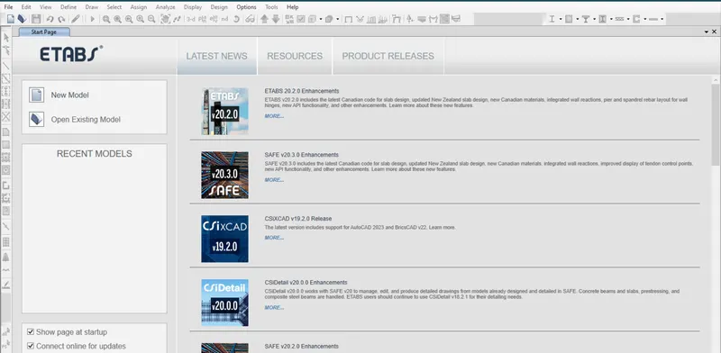
Open E tabs software and interface will look like this
Then click on the new model option to create a specific model with elements column and beam of dimensions
column - 400 x 400 mm
beam - 300 x 400 mm
slab - 150 mm
Grade of concrete Material - M30
Grade of reinforcement rebars - Fe415
Load on infill walls - 10kn/m2
Live load on floors - 3kn /m2
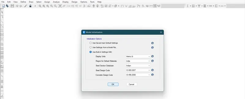
Then a new dialogue box will open
Select the properties which we have chosen in challenge 6
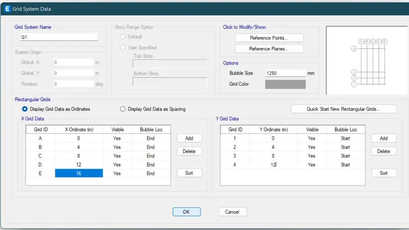
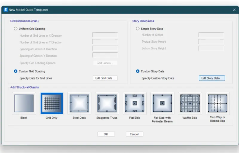
Then click on the custom grid spacing and click on edit grid data
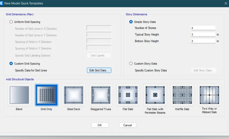
Then provide four grid at a distance of 4 m in X coordinate and provide three grids in wide direction at a distance of 4 m and then click on ok
Then click on the custom story data and click on the edit story data
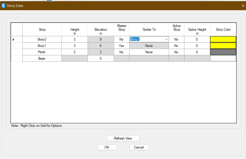
Provide the number of stories required and also mention the height
Here,
The story height is 3 m and the plinth height is 1.5 m
Make the story one as master story and other story similar to Story 1
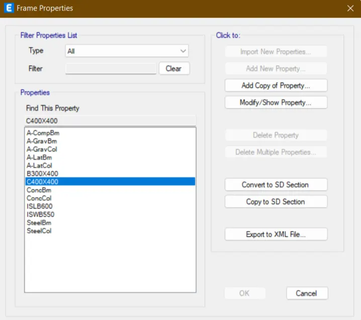
Then go to the define option and click on the frame properties and select the type of columns and beams which we want to provide
We can always modify or create new property as per our requirement
After defining the loads, slabs, beams and columns
Our created model will look like this
Here after column assigned in the model
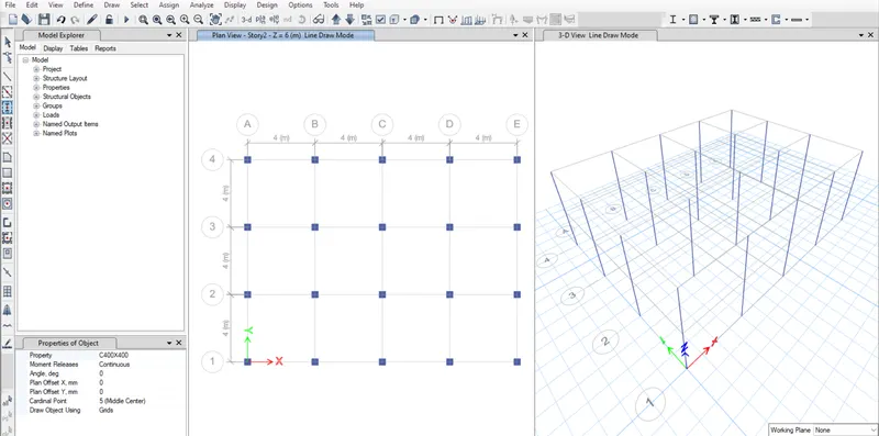
Now beams are attached
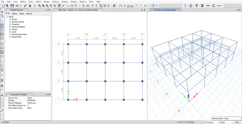
Then save the model file
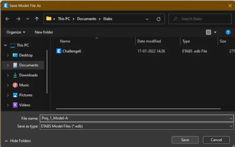
After that run the analysis by clicking on the run analysis or by shortcut key F5
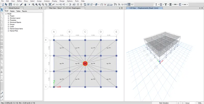
b.For model B :-
After saving the file of model a
For creating the model b and its properties
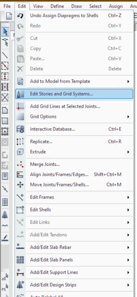
Go to edit option then go to edit story and grid system
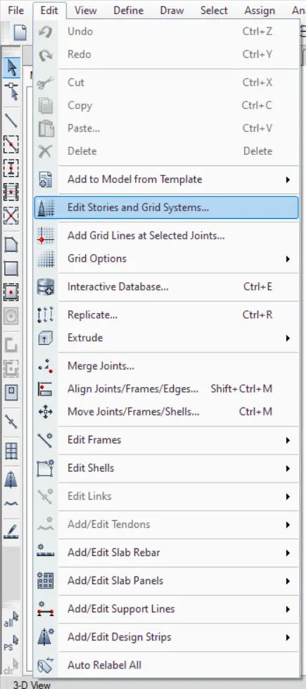
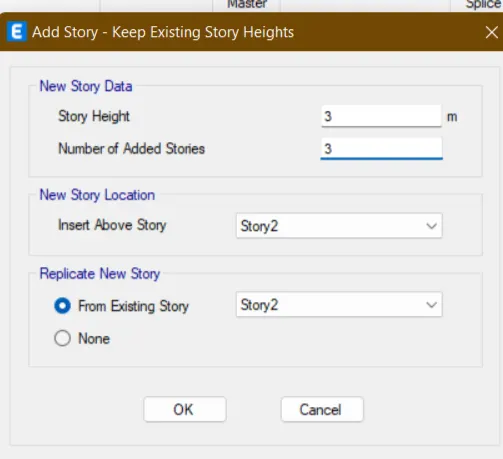
Then enter the number of added stories as 3
then click ok
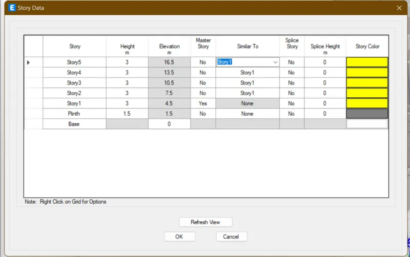
Now you can see that the stories have been added
Then change the similar to option to story 1 and then click ok
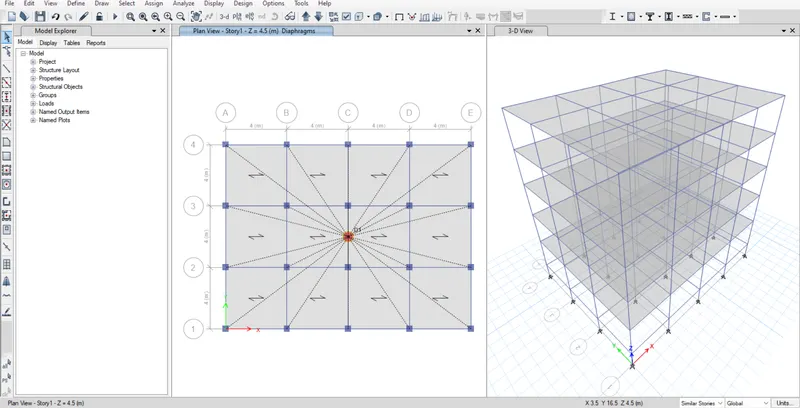
Now you can see that our model will look like this and then select the slab and find the diaphragm for it.
After that save the file and then run the analysis to see the result
c.For model C :-
Go to define then go to Section properties and then click on the frame sections
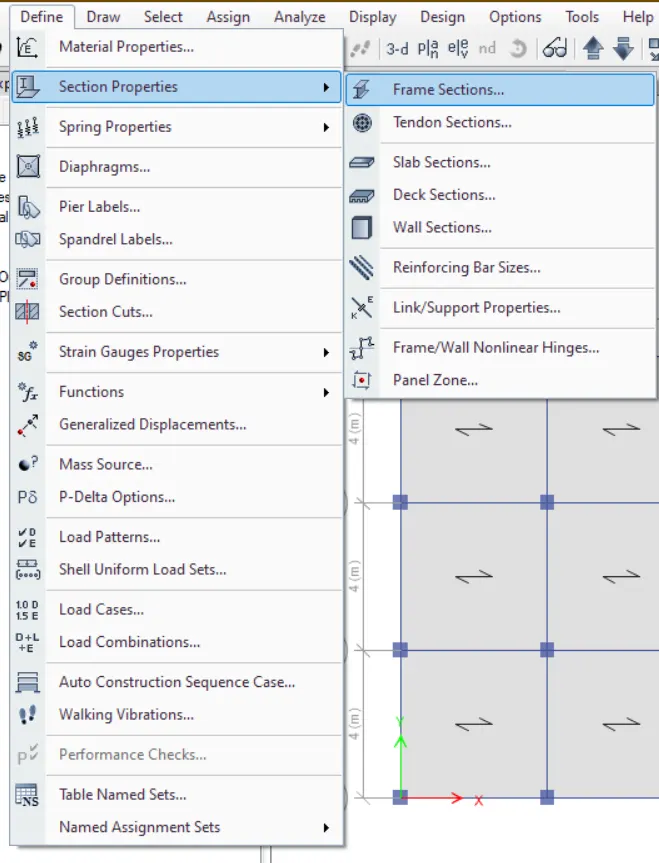
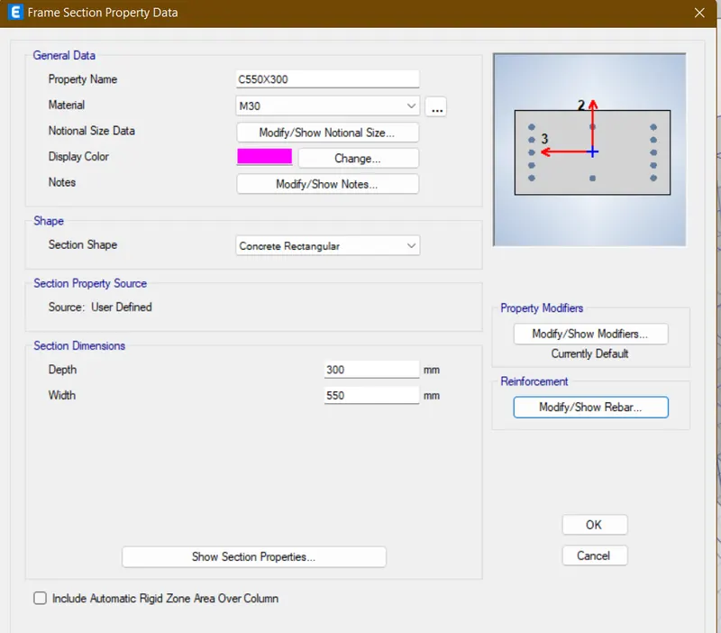
After that click on the modify or add option and then type the properties as
Property name - C550X300
Material- M30
depth -300
width -550 then click ok
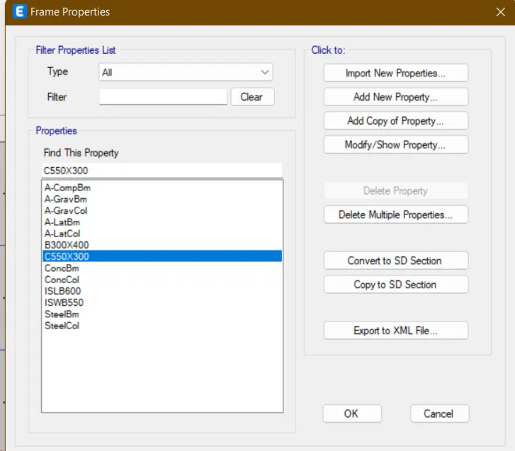
Then select the created property
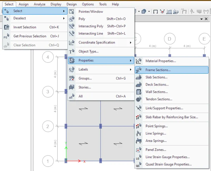
Then go to select then properties then click on the frame properties to select the column
Then go to assign then frame and then click on local axes.
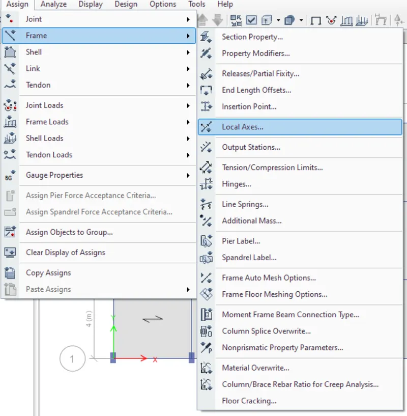
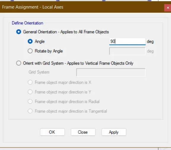
A new dialogue box will open
Go to angle and enter the angle at 90 degree and then click apply
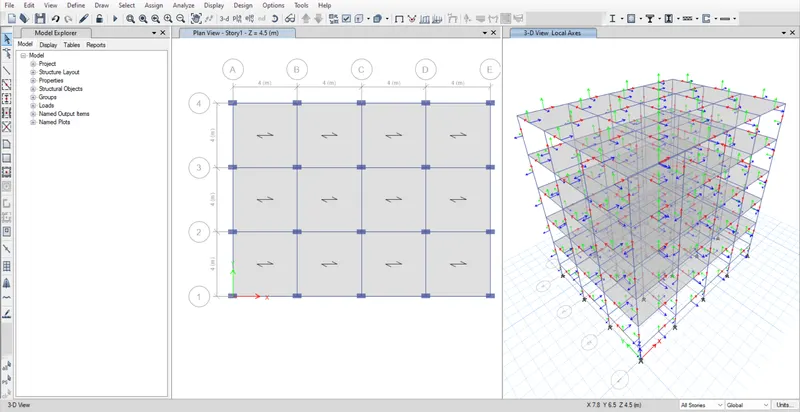
Now you can see that our selected columns have been rotated to 90 degree as per the given criteria in the question
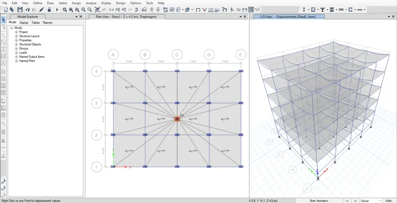
Now select the slab and assign the diaphragm for it
Save the model and run the analysis
d.For Model D :-
Do follow the same steps we followed for model C
Then enter the angle has zero degree and then click on ok button.
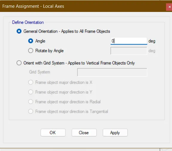
Now you can see that our selected column section have been rotated from 90 degree to 0 degree.
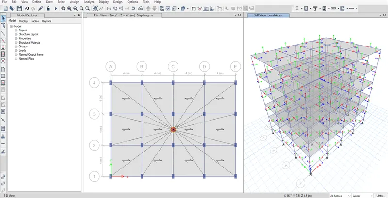
Select the slabs and then assign the diaphragm for the model
Save the model and then run the analysis for it
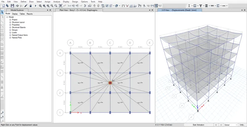
e.For Model E :-
Open the frame properties section and then create the required properties of columns
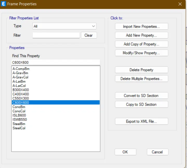
Then go to edit and click on the edit stories and grid systems and select the story which you want to see
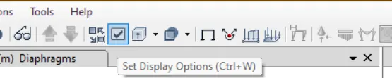
After that go to set display option
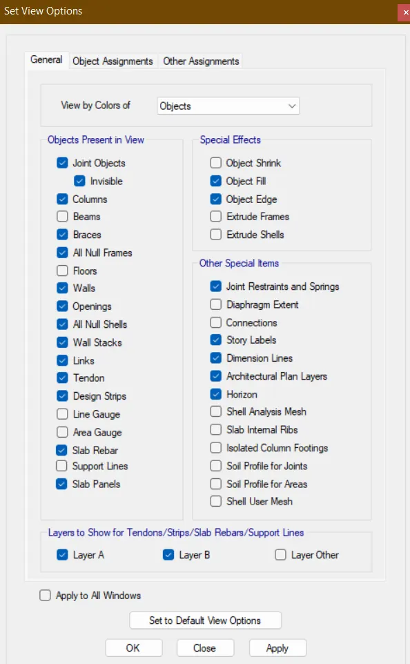
And uncheck the beams and floor s option and click apply
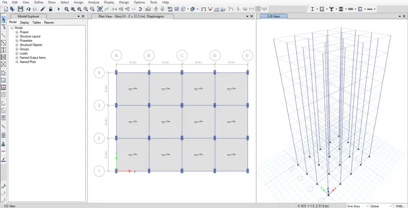
Now we can see that the columns only are visible now
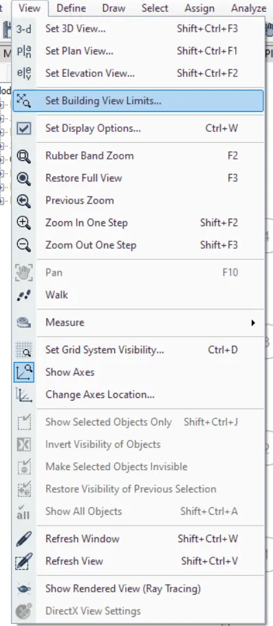
Then go to set building view limits option in the view button and assign the view limit from story 5 to story number 10
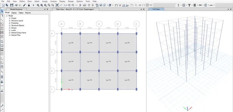
Now we can see that the upper five stories are visible
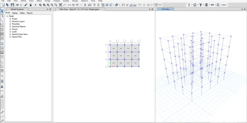
Select the columns
Then go to assign option then frame then section properties
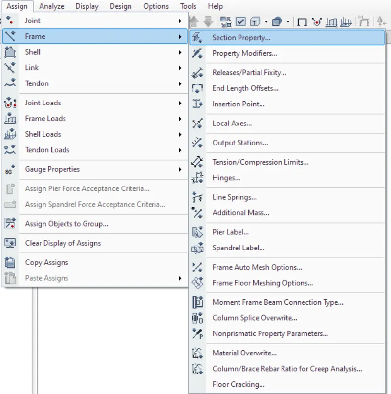
Select the created model property and click apply
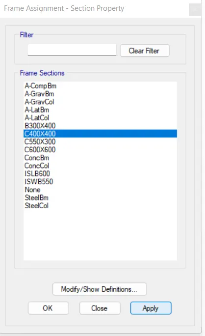
Hence the upper 5 stories property have been changed to colum 400 x 400
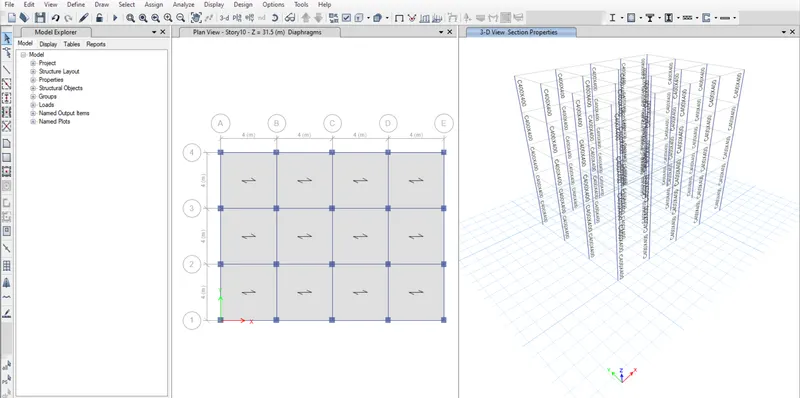
Also follow the same procedure to assign the bottom five stories as column 600 X 600
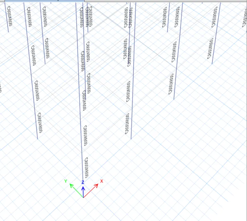
Hence the given story properties have been assigned in the model
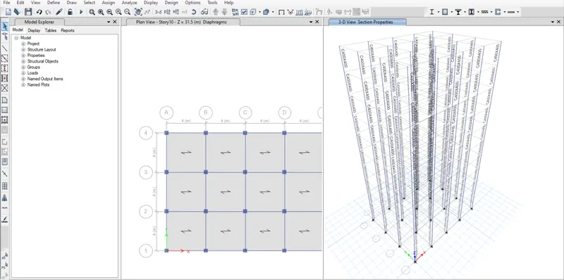
Then save the model and then run the analysis
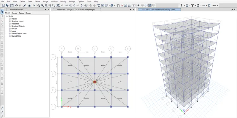
f.For model F:-
For model f just select the Apartment stories and then change the property as we have changed in for the model e as in the given question
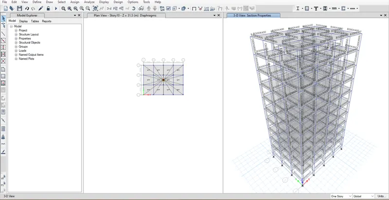
After that save the model naming model f and then run the analysis
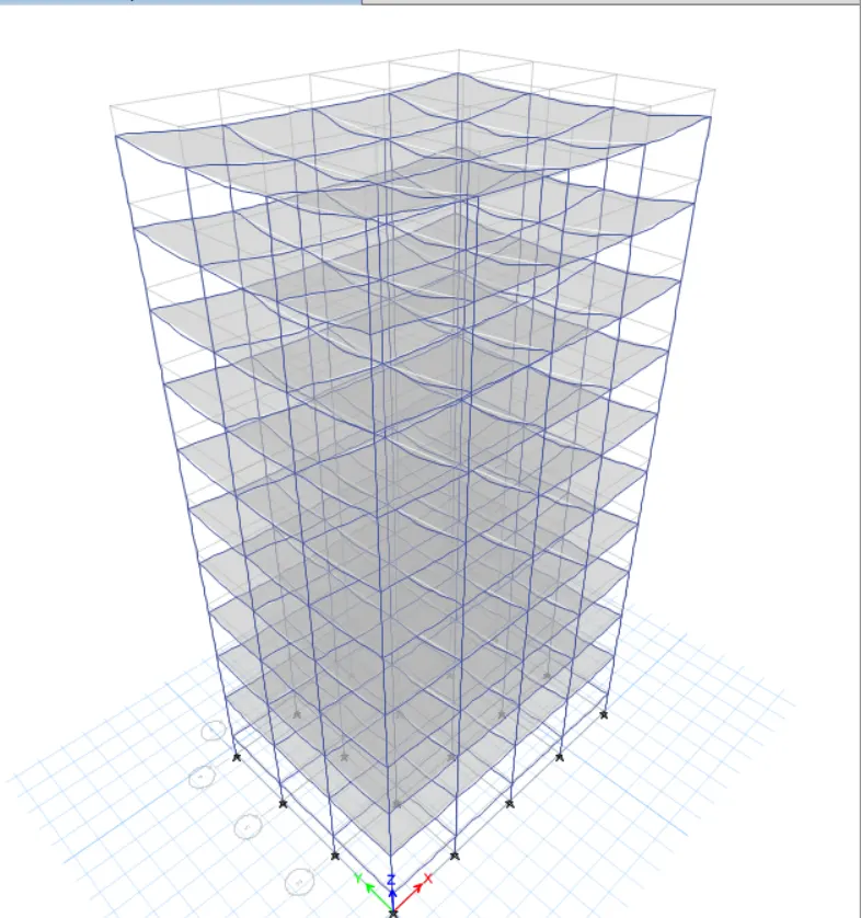
g.For model G :-
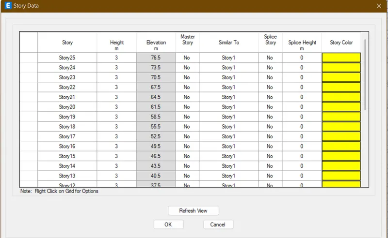
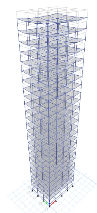
To at the stories to our model just go to the story data option and then add 15 stories as the required number of stories are 25
Change the similar to option from none to Story 1
Then click ok
Then go to view and click on set building view limits
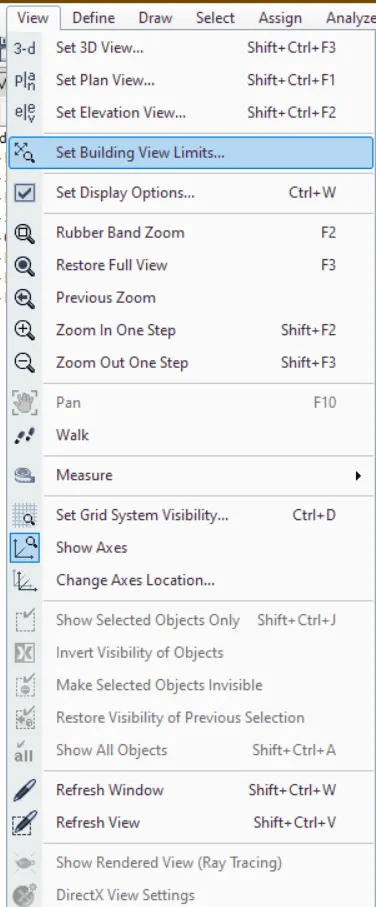
In the dialogue box
Go to the Set story range and set the range as bottom story story 21 and top story as story 25 then click ok
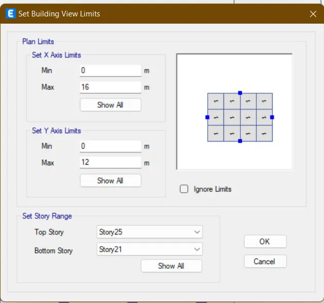
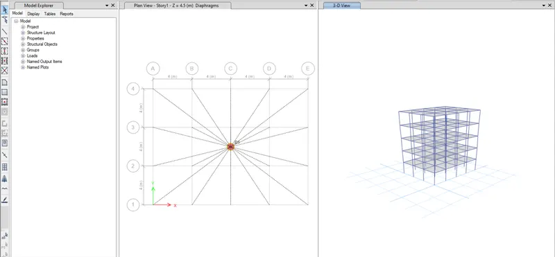
Now you can see that the only story from 21 to 25 are visible
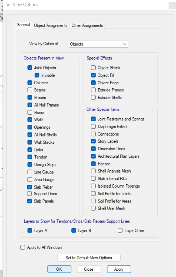
Then go to the set display option and un check the beam floor option from there and click ok
Now go to assign then frame then section property
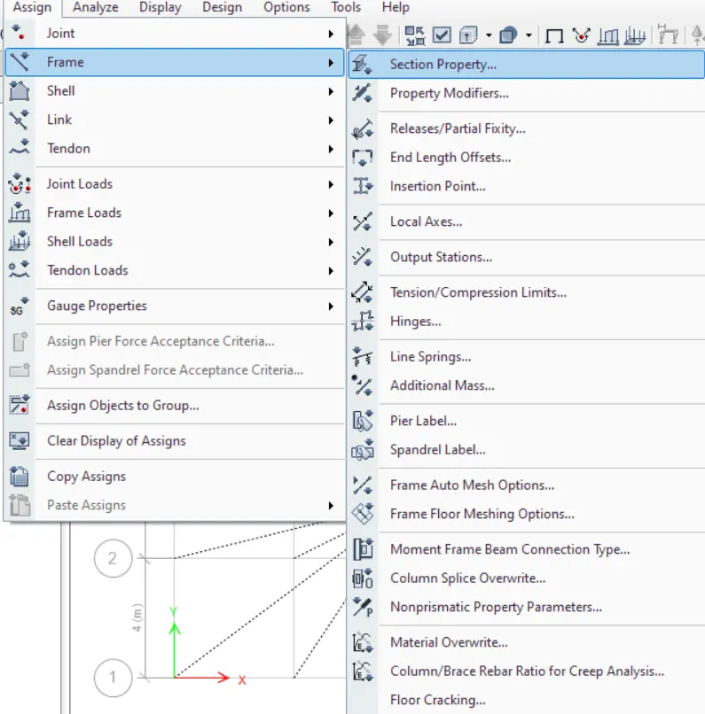
And select the c400x400 property from there for the upper 5 story and click apply
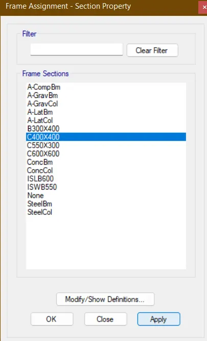
Follow the same step for the middle 10 stories of column 600 X 600 and the column will look like this
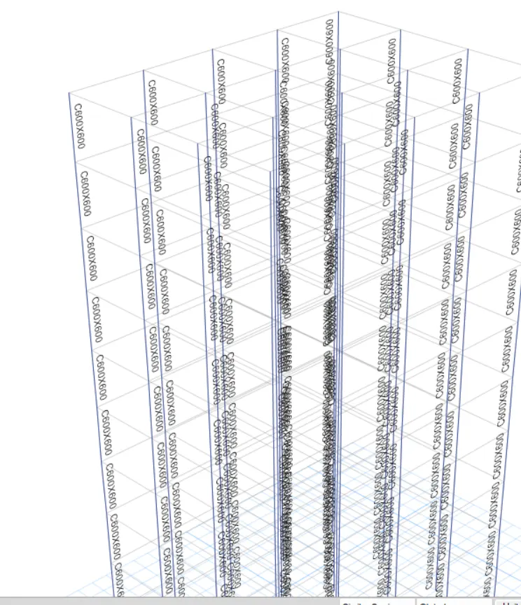
Follow the same procedure for the bottom 10 stories as column 800 x 800
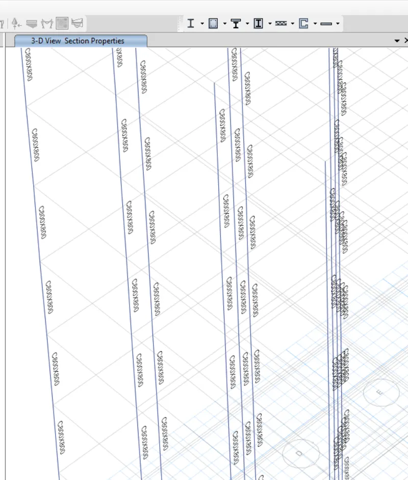
Then save the model and run the analysis
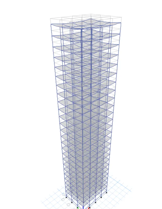
h.For Model H :-
First go to set display option and un check the beams and colum section from there
Then select all the columns
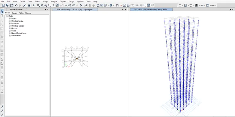
As you can see all the columns have been selected
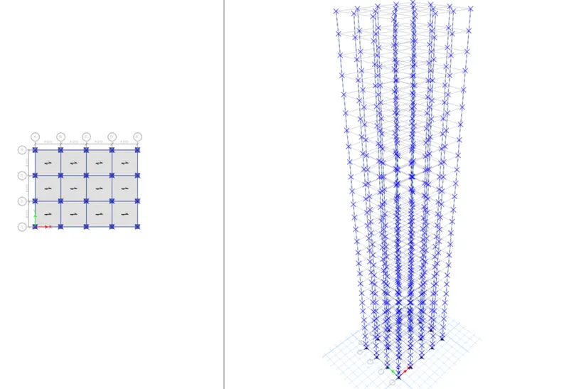
Then go to assign then frame then section property
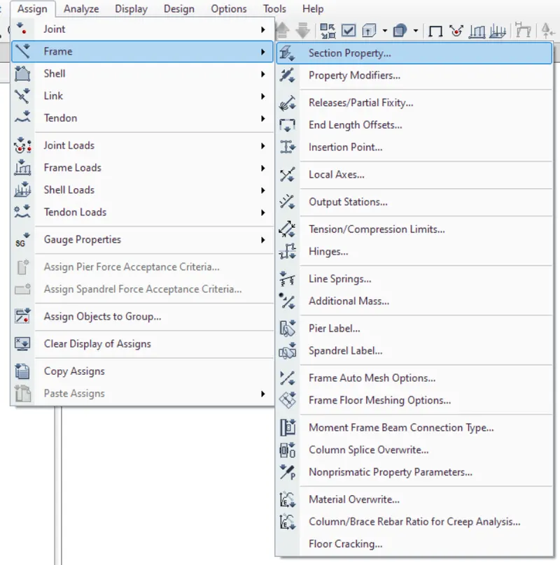
Then click on the C 800 x 800 property and click on apply
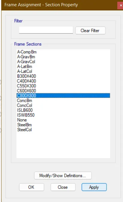
Now you can see that the property has been assigned
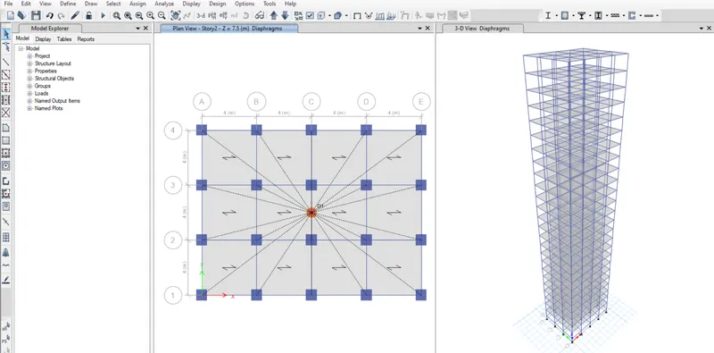
Save the model and run the analysis.
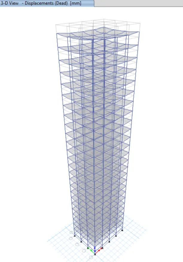
j. For Model J :-
First go to select then go to properties then slab sections
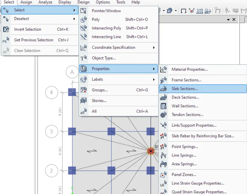
Then select the property of slab as S 150
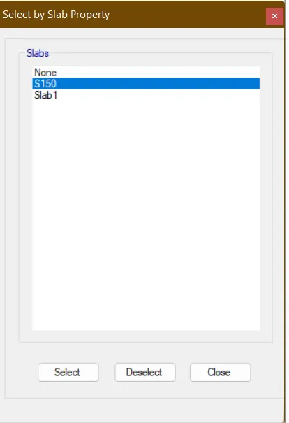
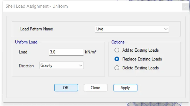
Then again go to assign then shell loads than uniform
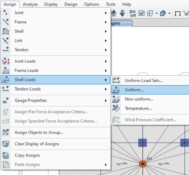
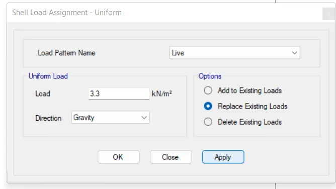
Now as we have assigned earlier the live load as 3 Kn/m2
In this question it has been said to increase the load by 10%
So the load has to be increased from 3 to 3.3 Kn/m2
Then click ok
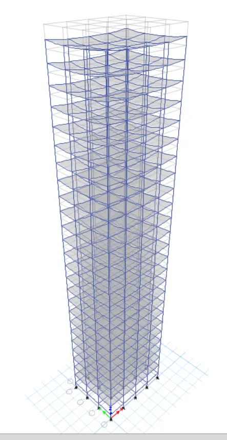
Then save the model and then run the analysis
k.For model K :-
We have to increase the imposed to load by 20% so the load will become 3.6 KN/m2
Then click ok
Save the model and then run the analysis.
RESULT :-
1.EFFECT OF STIFFNESS ON TIME PERIOD
For Building E - 1.731 sec
For Building F - 1.735 sec
For Building G - 4.17 sec
For Building H - 4.416 sec
The difference in time period occurred between the varying column size and uniform column size and it is shown that the varying column size are more stable because of the axis mass that is lumped at the top in uniform column size.So, mass in the building will induce more lateral displacement and that will provide more stiffness to the building so that's why the difference occurred.
2.EFFECT OF MASS ON TIME PERIOD :-
For building H :- 4.416 sec
For building J :- 4.425 sec
For building K :- 4.435 sec
As we know Mass is directly proportional to the lateral force, hence there will also be a increase in the time period of the building therefore the building will become a bit flexible.
3.EFFECT OF BUILDING HEIGHT ON TIME PERIOD :-
For Building A :- 0.5 sec
For Building B :- 1.036 sec
For Building F :- 1.735 sec
For Building H :- 4.416 sec
We also know from IS Codebook , that the time period is directly proportional to the height of the building. So time period will always increase while increase in the height of the building for any model.
4.EFFECT OF COLUMN ORIENTATION ON TIME PERIOD :-
For Building B :- 1.036 sec
For Building C :- 1.145 sec
For Building D :- 1.12 sec
Hence for mode 1 our building model is deflected in Xdirection
And for mode 2 ,the deformation in the building occurs in Y direction.
Comparing building c and d which are having different column size
As in X direction the column size is Greater in building c and smaller in building Y, so the lateral load will be more in building D as compared to building C because it is having small colum size in X direction.
5.EFFECT OF FLEXURAL STIFFNESS OF STRUCTURAL ELEMENTS ON MODE SHAPES :-
For building B :-
a.Flexural stiffness of beams close to zero :-
On changing the moment of inertia for the building as 10% from 100%
So the analysis result which we got after analysing the building model is 2.627 sec
b.Full Flexural stiffness of beams :- 1.036sec
Hence, if considering of only 10% of flexural stiffness On The Beam as compared to full flexural stiffness of beams we got near about double of the time period. And this is the result and effect of flexural stiffness of beams.
6.EFFECT OF FLEXURAL STIFFNESS OF VERTICAL MEMBERS ON MODE SHAPES :-
For building H :-
a.Axial cross section for columns close to zero :-
For this let us consider only 10% of axial area of ModelH
Changing the value of Cross section area from 1 to 0.1
Analysis result :- 5.991 sec
b. Full axial cross section of columns :- 4.416 sec
As we can clearly see the difference between both the time periods and hence the vertical member always play a vital role in Time periods of any model and it's strength also.
7.EFFECT OF DEGREE OF FIXITY AT COLUMN BASE ON MODE SHAPE :-
For building B :-
a.Column support pinned :- 1.036sec
b.Column support fixed :-
Hence changing the pinned to fixed support in the model b
And after changing the time period we got from analysis of the building model is 0.941 sec.
Hence from the above conditions we can come to a conclusion that , more the fixity of the Columns in the model, the deflection of the model will be lesser.