Project 1_Comparative study of different storey buildings for Seismic forces
AIM & INTRODUCTION :
AIM :
- To create various building models with varying column and Beam sizes and Analyse the Period of Frequency of the Created Models upto 25 Stories.
INTRODUCTION :
- The E-TABS is used to create a structural building model using tools in it.
- Here, in E-TABS the deflection of the building due to the many load such as Dead, Live, SuperDead etc.
- All the properties of the Concretes and Rebars are created as per the appropriate IS CODES.
- The required load can be applied on the created Structural Model as per Soil type and Zone.
- We can Run the Analysis test over the Structural model created to analyse its performance according to the applied load.
- The Properties of the Framed and Slab Sections can be edited as per requirement.
- We can add as many number of stories required as per the requirement to analyse.
- The results can be seen in the Model information Table.
PROCEDURE :
1. BUILDING - A : (2 STOREY BUILDING)
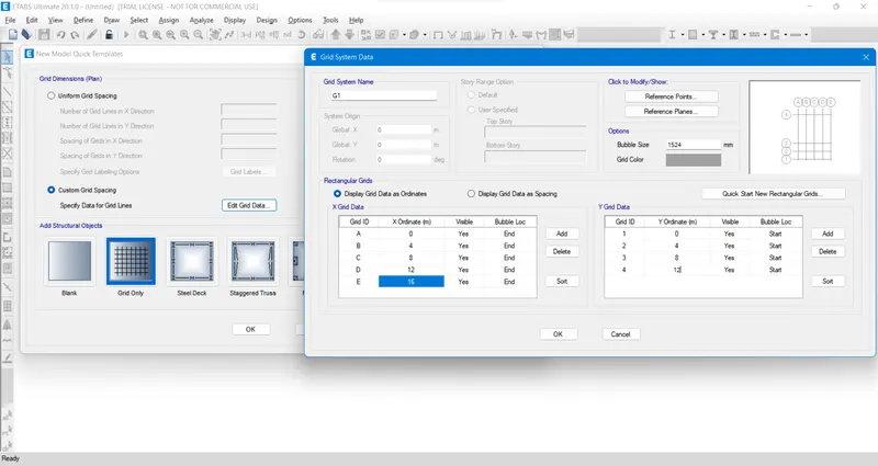
- Open E-TABS software then click New Model to open a New workspace to create a Building - A.
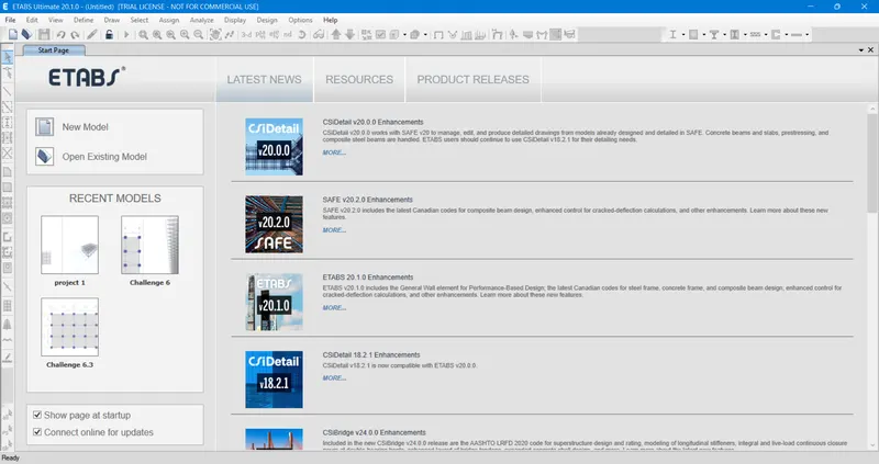
- After opening a New Model workspace, the Model information Tab will be displayed then click and select Use Built-in Settings with:
- Then select Display Units = Metric SI, Region for Default Materials = India, Steel Section Database = Indian, Steel Design Code = IS 800 2007, Concrete Design Code = IS 456 2000.
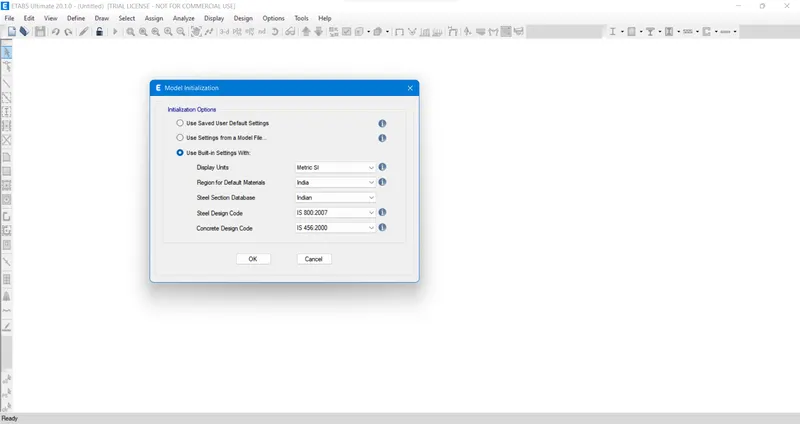
- After that the New Model Quick Templates Tab will open, from there click Custom Grid Spacing < Edit Grid Data.
- Then the Grid System Data tab will be opened, click add in X Grid Data to add the Grid ID - E and edit the X ordinate (m) as A = 0m, B = 4m, C = 8m, D = 12m, E = 16m.
- Followed by edit the Y ordinate (m) as 1 = 0m, 2 = 4m, 3 = 8m, 4 = 12m and click OK.
- After setting Grid System Datas, click and select Custom Story Data at the same New model Quick Template tab to open Story data Tab.
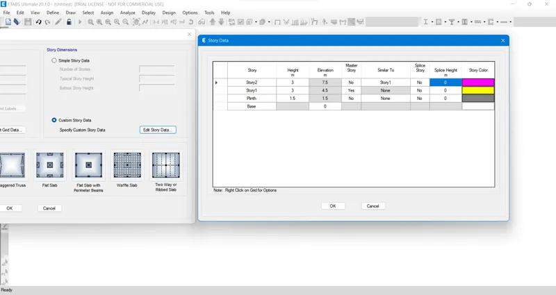
- Here in Story Data tab < select and set the appropriate stories as per requirement such as we need 2 story only for BUILDING - A.
- Form the ground level Set height of Base = 0m, Plinth = 1.5m, Story1 = 3m, Story2 = 3m.
- Followed by make the Story 1 = Master story and Make story2 = Similar to story1 then click OK.
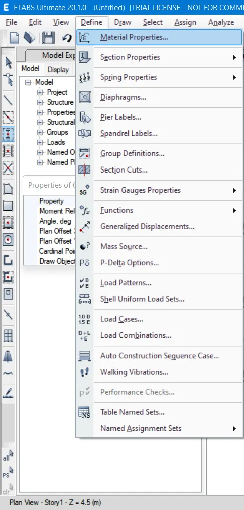
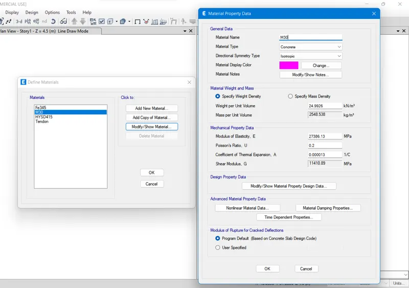
- Then Create Material Property for concrete as required by selecting Define < Material Properties < Add New material < Material Property Data.
- From Material Property Data tab < Material Name = M30, Material Type = Concrete and click OK.
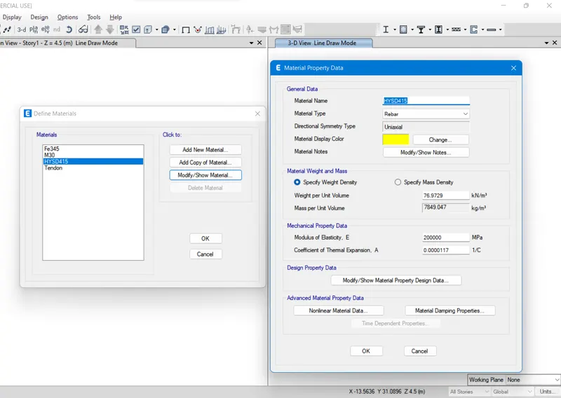
- Likewise Create Material Property for Rebar as required by selecting Define < Material Properties < Add New material < Material Property Data.
- From Material Property Data tab < Material Name = HYSD415, Material Type = Rebar and click OK.
- After creating Material properties try creating Section properties of Frame section such as Beams, Columns and Slabs.
- First to create Section property of Beam, cilck and select Define < Section Properties < Frame sections < Frame properties Tab.
- From the Frame properties Tab < Add New Property = Concrete (Rectangular section) and click OK.
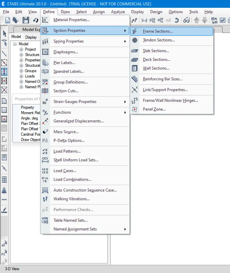
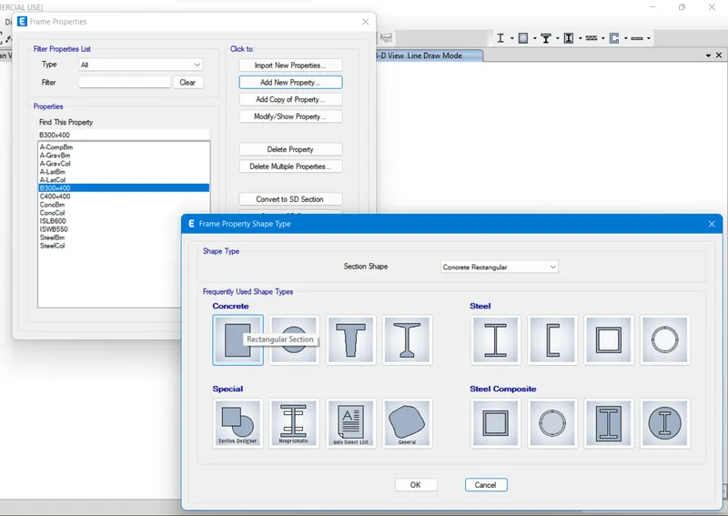
- After selecting the Rectangular section (concrete), the new tab will be opened in the name of Frame Section Property Data .
- From Frame Section Property Data Tab in General Data < Property Name = B300x400, Material = M30 and in Section Dimensions < Depth = 400mm, Width = 300mm and click OK.
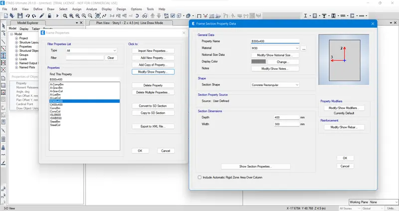
- Likewise to create Section property of Column, cilck and select Define < Section Properties < Frame sections < Frame properties Tab.
- From the Frame properties Tab < Add New Property = Concrete (Rectangular section) and click OK.
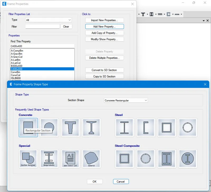
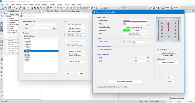
- After selecting the Rectangular section (concrete), the new tab will be opened in the name of Frame Section Property Data .
- From Frame Section Property Data Tab in General Data < Property Name = C400x400, Material = M30 and in Section Dimensions < Depth = 400mm, Width = 400mm and click OK.
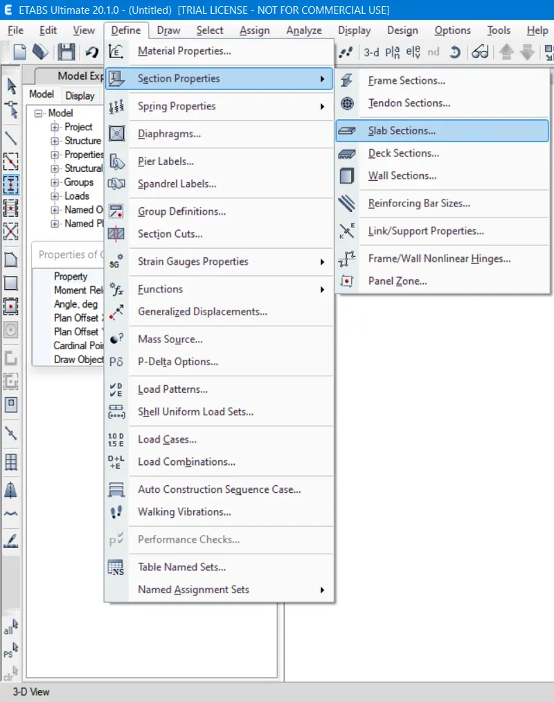
- Followed by to create Section property of Slab, cilck and select Define < Section Properties < Slab sections < Slab properties Tab.
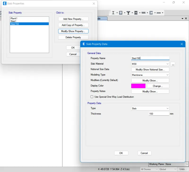
- From Slab Properties Tab < Slab Property < Add New Property < Slab property Data Tab will be opened.
- In Slab property Data Tab < General Data < Property Name = Slab150, Slab Material = M30, Modeling Type = Membrane, Thickness = 150mm and click OK.
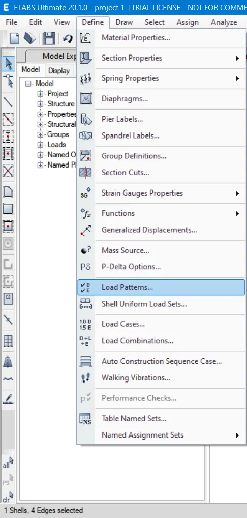
- Then set the Load Pattern by selecting Define < Load Patterns to open Define Load Patterns Tab.
- From Define Load Patterns Tab < Load = Dead, Type = Dead, Self Weight Multiplier = 1, Auto Lateral Load = 0 and Click Add New Load to add a created load .
- Followed by Edit Load = Live, Type = Live, Self Weight Multiplier = 0, Auto Lateral Load = 0 and Click Add New Load to add a created load .
- Followed by Edit Load = BrickWall, Type = SuperDead, Self Weight Multiplier = 0, Auto Lateral Load = 0 and Click Add New Load to add a created load .
- Followed by Edit Load = EQX, Type = Seismic, Self Weight Multiplier = 0, Auto Lateral Load = IS 1893 2016 and Click Add New Load to add a created load .
- Followed by Edit Load = EQY, Type = Seismic, Self Weight Multiplier = 0, Auto Lateral Load = IS 1893 2016 and Click Add New Load to add a created load and click OK.
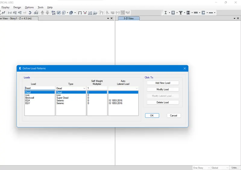
- Then the Added seismic load EQX's Lateral Load should be Modified.
- For that Click the EQX load < Modify Lateral Load < Indian IS 1893 2016 Seismic Loading Tab will be opened.
- From the opened Tab < Direction and Eccentricity = X Dir, Seismic Coefficient (Per code) = 0.16 and click OK.
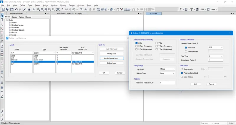
- Likewise the Added seismic load EQY's Lateral Load should also be Modified.
- For that Click the EQY load < Modify Lateral Load < Indian IS 1893 2016 Seismic Loading Tab will be opened.
- From the opened Tab < Direction and Eccentricity = Y Dir, Seismic Coefficient (Per code) = 0.16 and click OK.
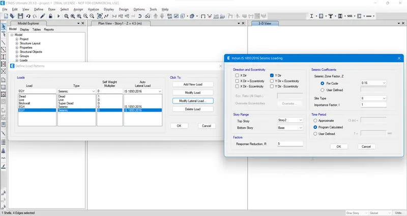
- Then after the creating Load Patterns, the Created Columns should be allowed to be assigned at the intersection points of the created grid lines.
- For that first click and change the Stories = All stories and select the tool Quick Draw Columns.
- After selecting the Column assigning Tool, try to click the intersection points of the grids and the columns will be assigned as per the image below.
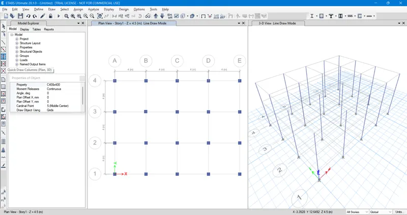
- Likewise the columns , the Created Beam property should be allowed to be assigned in between the intersection points of the created grid lines.
- For that as we said before click and change the Stories = All stories and select the tool Quick Draw Beams/Columns.
- After selecting the Beams/Columns assigning Tool, try to click the lines inbetween the intersection points of the grids and the beams will be assigned as per the image below.
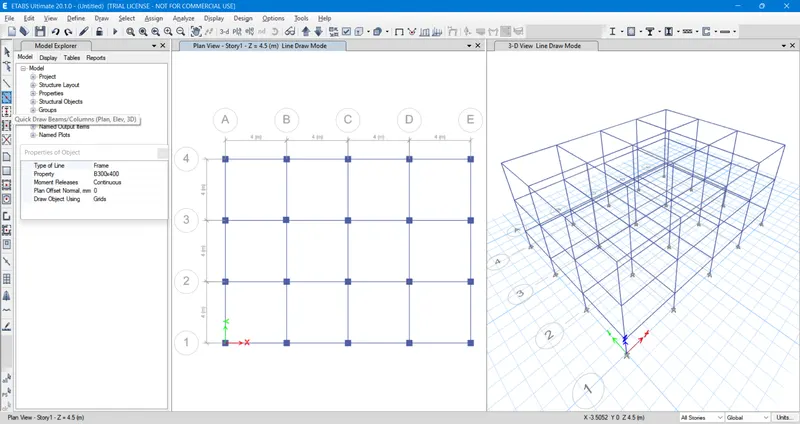
- Followed by the Columns and Beams, the Created Slab property should also be allowed to be assigned at the center area inbetween all the four connected beams over grid lines.
- To assign the slab at the floor level, we should select Plan < First story.
- From the First story plan we should click and change the Stories = Similar stories and select the tool Quick Draw Floor/Wall.
- After selecting the Floor/Wall assigning Tool, try to click the the space present inbetween the four beams of the grids and the slabs will be assigned as per the image below.
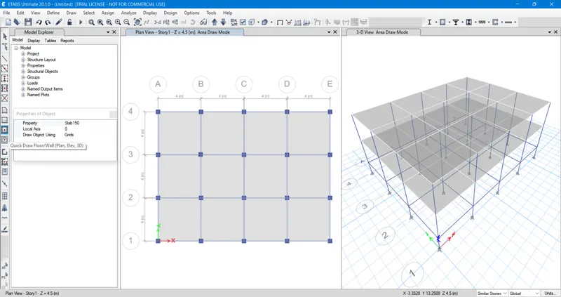
- Then select all assigned beams by clicking Select < Properties < Frame sections < Select by frame property Tab < B300x400.
- After selecting B300x400 Beam click Select to select all the beams assigned to the Building Model - A.
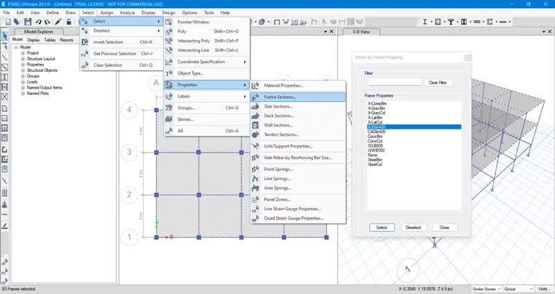
- Then apply the created Brickwall load to the Beams by clicking Assign < Frame loads < Distributed < Frame Load Assignment - Distributed Tab.
- From the Frame Load Assignment - Distributed Tab < Load Pattern Name = Brickwall, Uniform Load = 10 kN/m and click Apply.
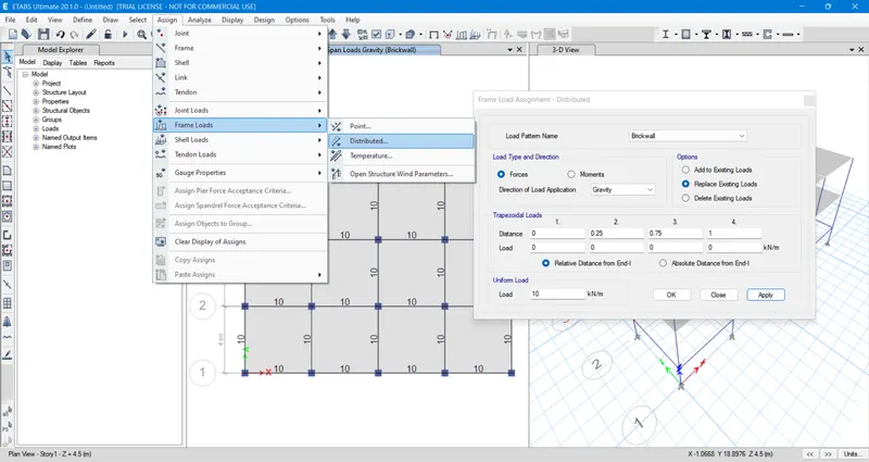
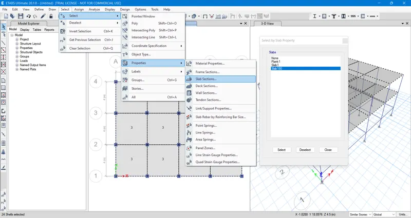
- Likewise the beam selection, now select all assigned Slabs by clicking Select < Properties < Slab sections < Select by Slab property Tab < Slab150.
- After selecting Slab150 Slab, click Select to select all the Slabs assigned to the Building Model - A.
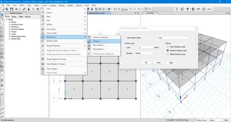
- Then apply the created Live load to the Slabs by clicking Assign < Shell loads < uniform < Shell Load Assignment - Uniform Tab.
- From the Shell Load Assignment - Uniform Tab < Load Pattern Name = Live, Uniform Load = 3 kN/m^3 and click Apply.
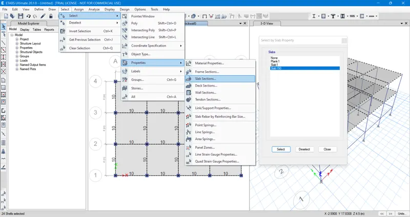
- Again select all assigned Slabs by clicking Select < Properties < Slab sections < Select by Slab property Tab < Slab150.
- After selecting Slab150 Slab, click Select to select all the Slabs assigned to the Building Model - A.
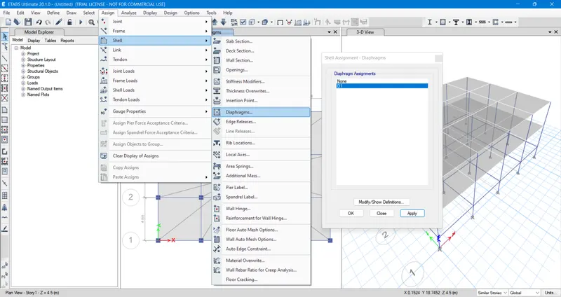
- Then try to assign Shell Diaphragms to the selected 150mm slab.
- For that click Assign < Shell < Diaphragms < D1 and click Apply.
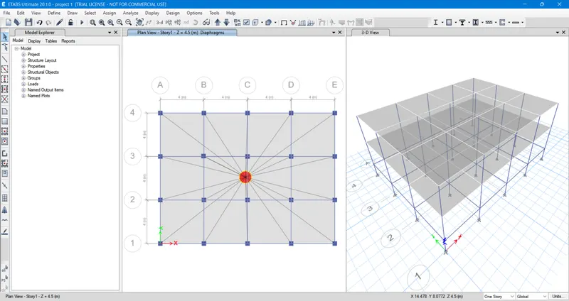
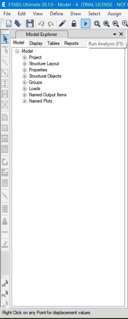
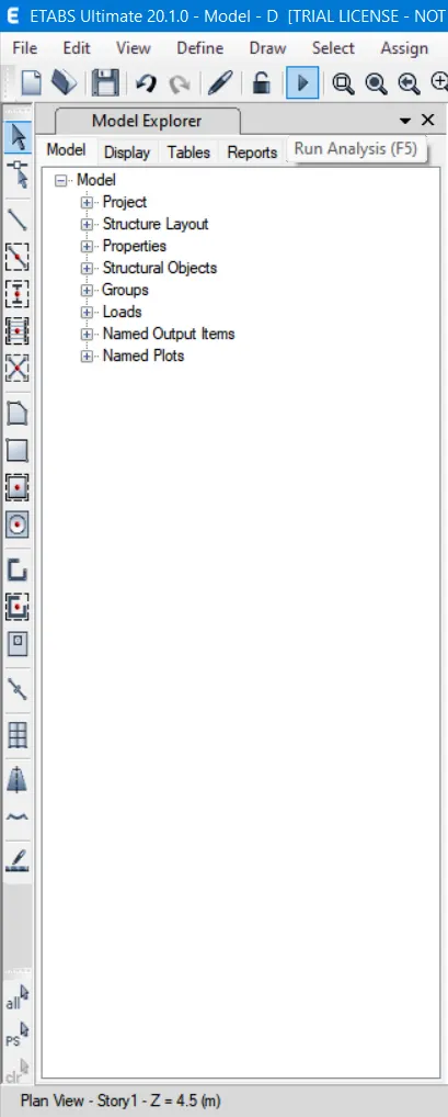
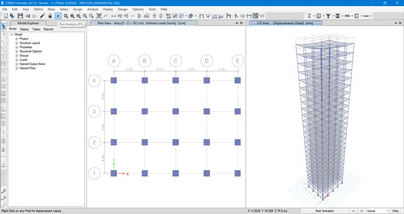
- After the assigning of the Diaphragms, we can Run Analysis from the option given in the tool bar.
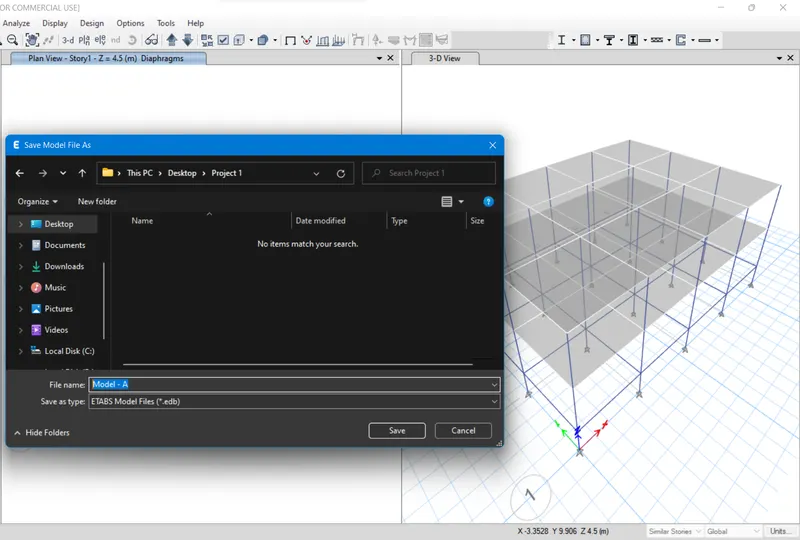
- Before strat analysing it will ask us to save the file at appropriate location and save the File name as Model - A.
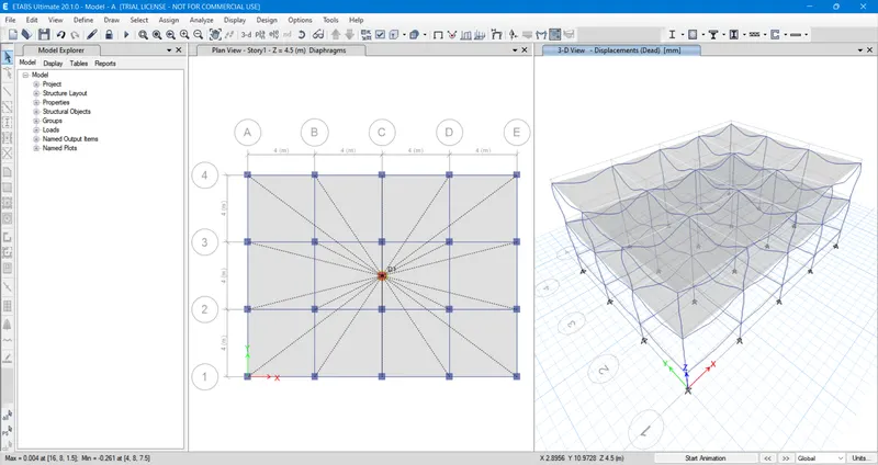
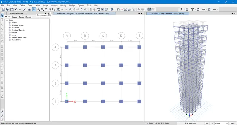
- After the completion of the analysis, the deformed shape of the Building will be visible in 3D view Window.
- We can see the Analysis Result from the Table option below the Model Explorer Window at the left side of the workspace.
- Atlast save the created Model - A from File < Save.
2. BUILDING - B : (BENCHMARK 5-STOREY BUILDING)
- After saving the Model - A, from the same file click File < Save as and save the file as Model - B.
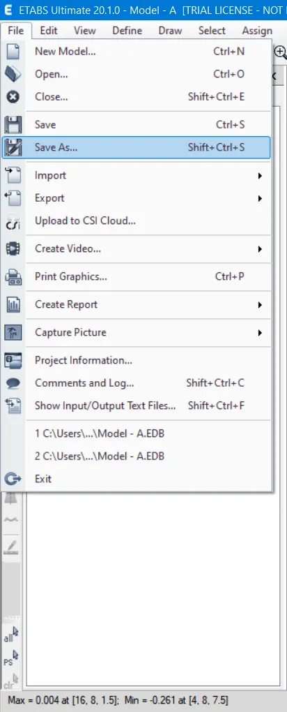
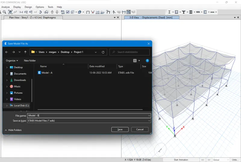
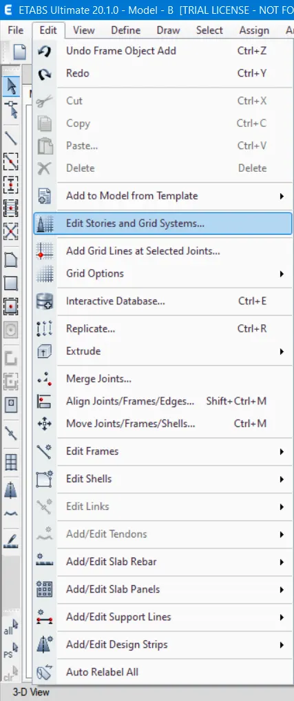
- Then edit the Strories and grids as per the Building - B requirement.
- For that Click and select Edit < Edit Stories and Grid Systems < Edit story and Grid System Data Tab will be opened.
- From the Tab opened Click and select Modify/show story Data < Stroy Data .
- In story data right click above the existing created last story and select Add story < Keep Existing Story Heights .
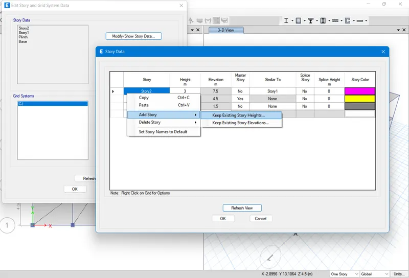
- Then a new tab will be opened in the name of Add story - Keep existing story heights.
- From Add stroy < New Story Data < Story Height = 3m, Number of Added Stories = 3 and click OK to get total of 5 Stories.
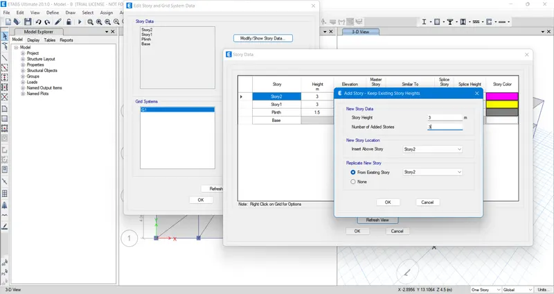
- After adding the additional 3 stories we get total of 5 Stories and change the Similar To for those added stories as Story 1.
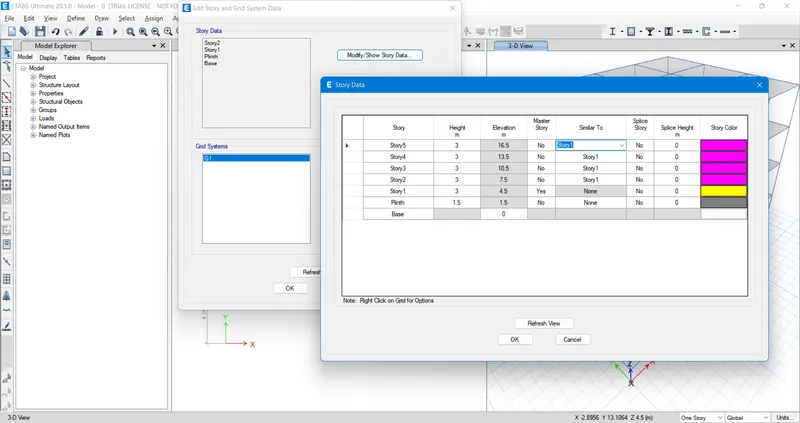
- Then check whether the applied Superdead load for Beams upto the story 2 is applied to the additionally added 3 stories.
- For that Click the Display Frame Load Assigns option in the Tool bar above Workspace.
- The show frame loads Tab will be opened.
- In the opened tab select Load pattern = BrickWall and click OK to see the applied Superdead load of 10kN over all Beams.
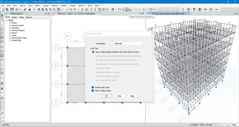
- Likewise check whether the applied Live load for Slabs upto the story 2 is applied to the additionally added 3 stories.
- For that Click the Display Shell Load Assigns option in the Tool bar above Workspace.
- The Show Shell loads Tab will be opened.
- In the opened tab select Load pattern = Live and click OK to see the applied Live load of 3kN over all Slabs.
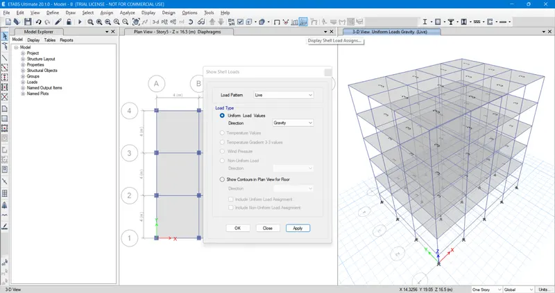
- Then select all assigned Slabs by clicking Select < Properties < Slab sections < Select by Slab property Tab < Slab150.
- After selecting Slab150 Slab, click Select to select all the Slabs assigned to the Building Model - B.
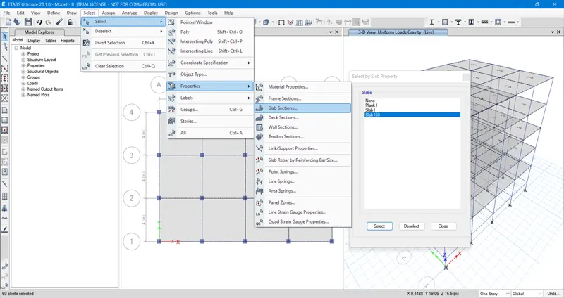
- Then assign Shell Diaphragms to the selected 150mm slab.
- For that click Assign < Shell < Diaphragms < D1 and click Apply.
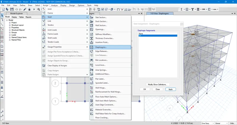
- After the assigning of the Diaphragms, we can Run Analysis from the option given in the tool bar.
- After the completion of the analysis, the Deformed shape of the Building will be visible in 3D view Window.
- We can see the Analysis Result from the Table option below the Model Explorer Window at the left side of the workspace.
- Atlast save the created Model - B from File < Save.
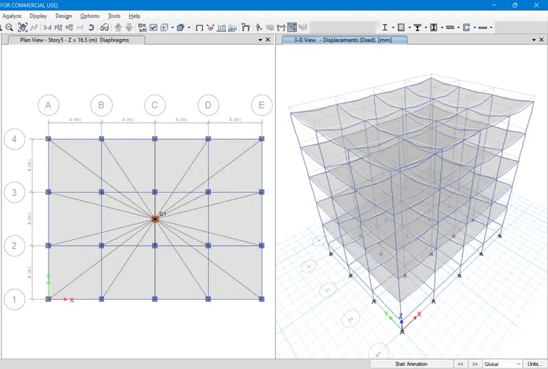
3. BUILDING - C : (BENCHMARK BUILDING WITH RECTANGULAR COLUMNS ORIENTED ALONG X-DIRECTION)
- After saving the Model - B, from the same file click File < Save as and save the file as Model - C.
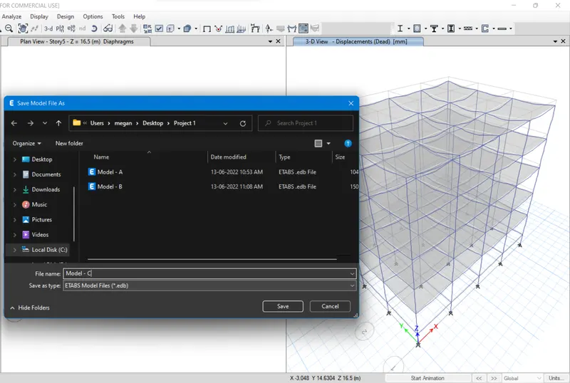
- Here in this Model - C, the Column sizes should be change from C400x400 to C550x300 as per required.
- For that select Define < Section properties < Frame sections.
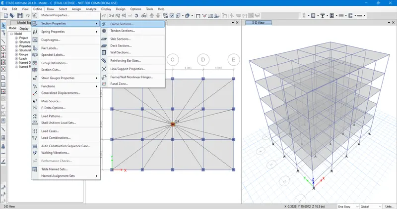
- After that the Frame properties Tab will be opened, in it select existing C400x400 and click Modify/Show Property.
- Then the Frame Section property Data Tab will be opened, here change the Property Name = C550x300, Depth = 300, Width = 550.
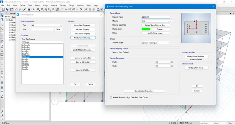
- After the creation of the Column C550x300, select all the columns to make it oriented along the X- Direction.
- For that Click Select < Properties < Frame sections < C550x300 and click OK.
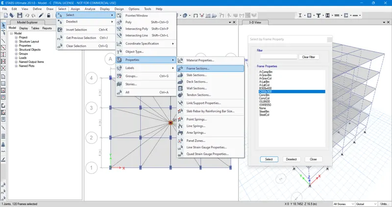
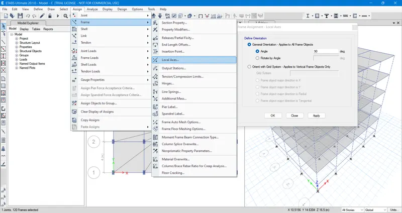
- Here the created columns orientation should be along with the X-Direction.
- So Select Assign < Frame < Local Axes < Frame Assignment - Local Axes Tab will be opened.
- From the opened Tab click General Orientation < Angle = 90 deg and click Apply.
- Then select all assigned Slabs by clicking Select < Properties < Slab sections < Select by Slab property Tab < Slab150.
- After selecting Slab150 Slab, click Select to select all the Slabs assigned to the Building Model - C.
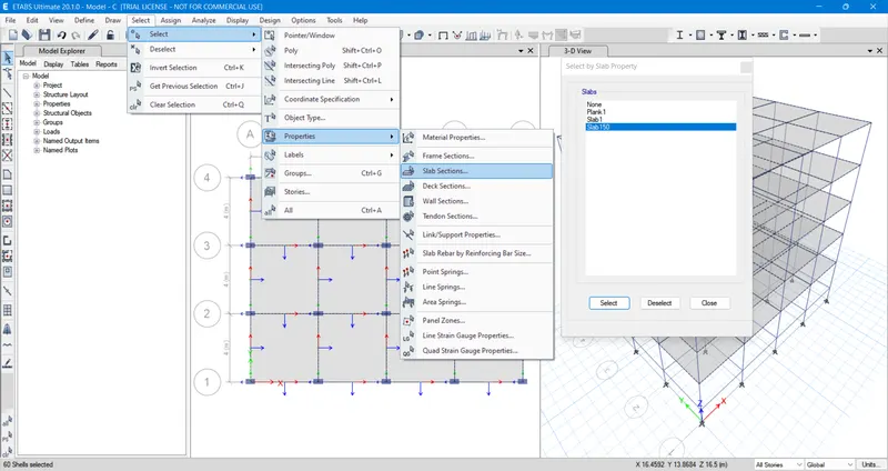
- Then try to assign Shell Diaphragms to the selected 150mm slab.
- For that click Assign < Shell < Diaphragms < D1 and click Apply.
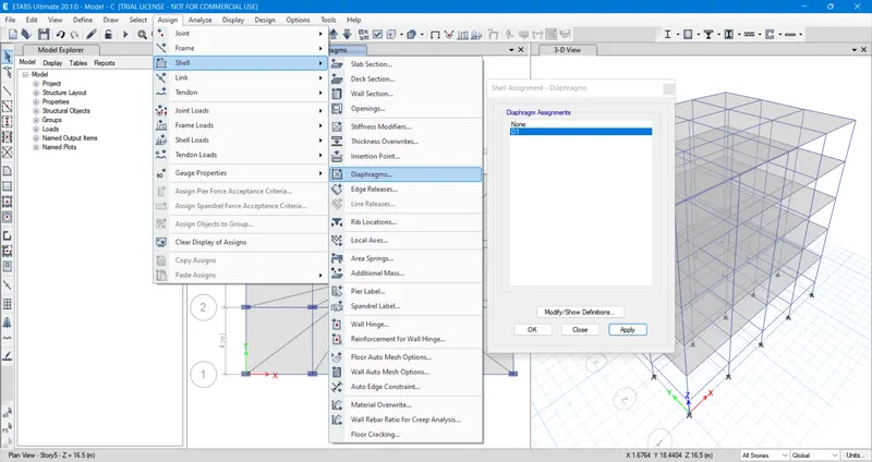
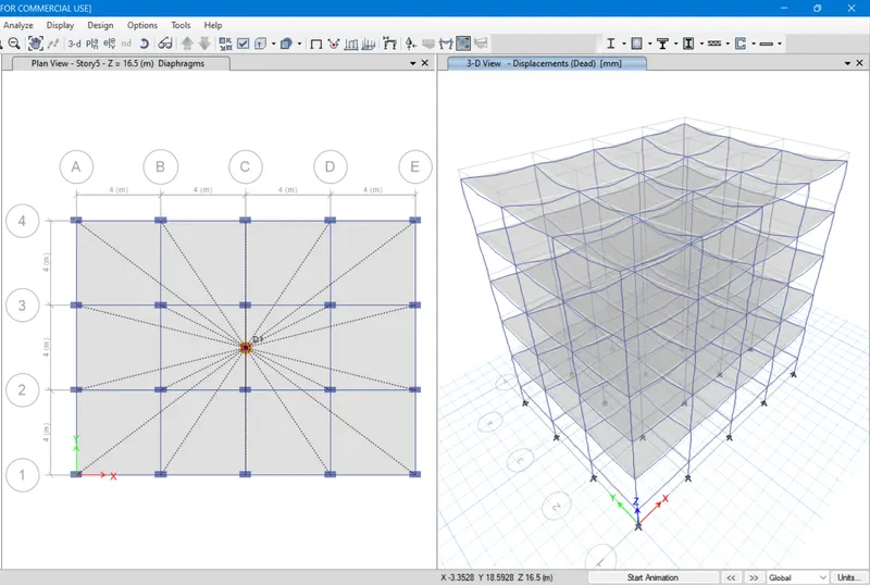
- After the assigning of the Diaphragms, we can Run Analysis from the option given in the tool bar.
- After the completion of the analysis, the deformed shape of the Building will be visible in 3D view Window.
- We can see the Analysis Result from the Table option below the Model Explorer Window at the left side of the workspace.
- Atlast save the created Model - C from File < Save.
4. BUILDING - D : (BENCHMARK BUILDING WITH RECTANGULAR COLUMNS ORIENTED ALONG Y-DIRECTION)
- After saving the Model - C, from the same file click File < Save as and save the file as Model - D.
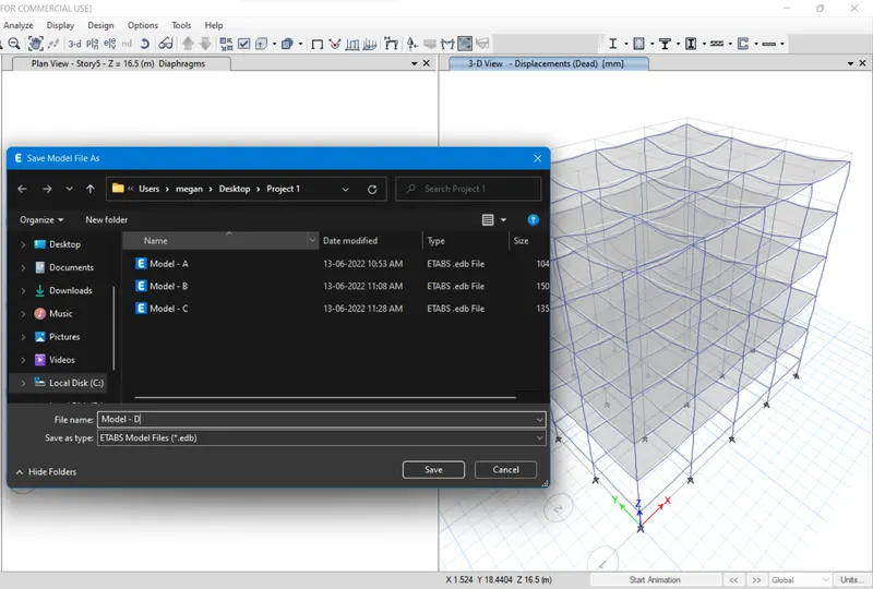
- After that select all the columns to make it oriented along the Y- Direction as per Building Model - D requirement.
- For that Click Select < Properties < Frame sections < C550x300 and click OK.
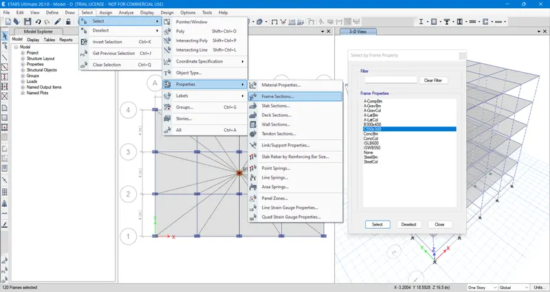
- Here the created columns orientation should be along with the Y-Direction.
- So Select Assign < Frame < Local Axes < Frame Assignment - Local Axes Tab will be opened.
- From the opened Tab click General Orientation < Angle = 0 deg and click Apply.
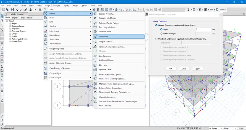
- Then select all assigned Slabs by clicking Select < Properties < Slab sections < Select by Slab property Tab < Slab150.
- After selecting Slab150 Slab, click Select to select all the Slabs assigned to the Building Model - D.
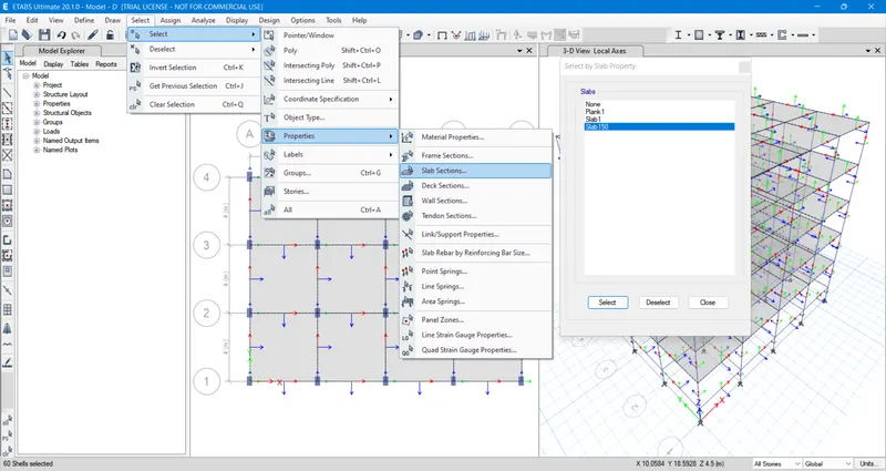
- Then try to assign Shell Diaphragms to the selected 150mm slab.
- For that click Assign < Shell < Diaphragms < D1 and click Apply.
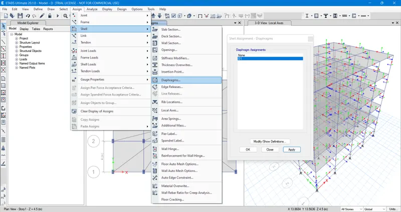
- After the assigning of the Diaphragms, we can Run Analysis from the option given in the tool bar.
- After the completion of the analysis, the Deformed shape of the Building will be visible in 3D view Window.
- We can see the Analysis Result from the Table option below the Model Explorer Window at the left side of the workspace.
- Atlast save the created Model - D from File < Save.
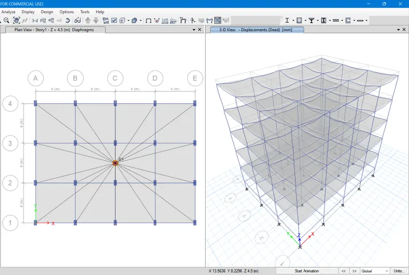
5. BUILDING E : (10 STOREY WITH VARYING COLUMN SIZE ALONG COLUMN HEIGHT)
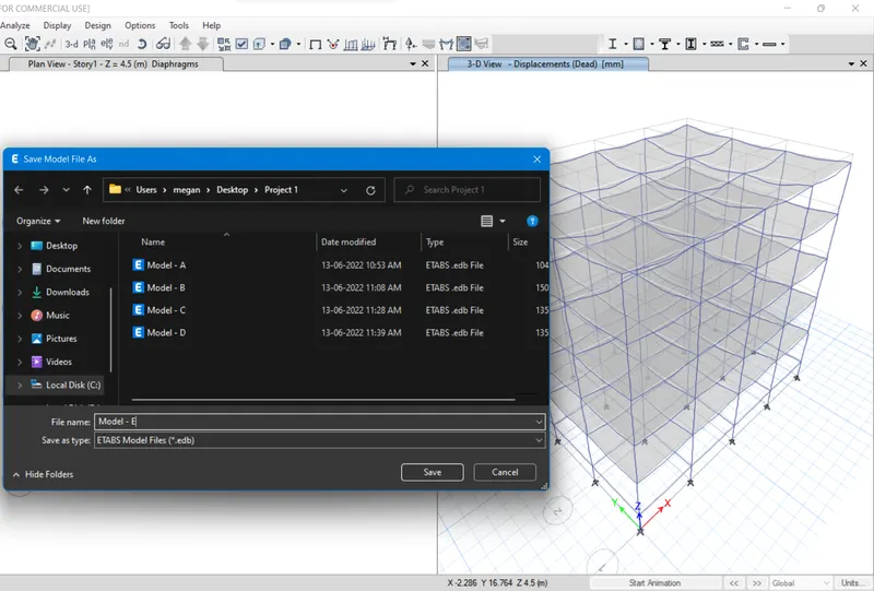
- After saving the Model - D, from the same file click File < Save as and save the file as Model - E.
- Then edit the Strories and grids as per the Building - E requirements.
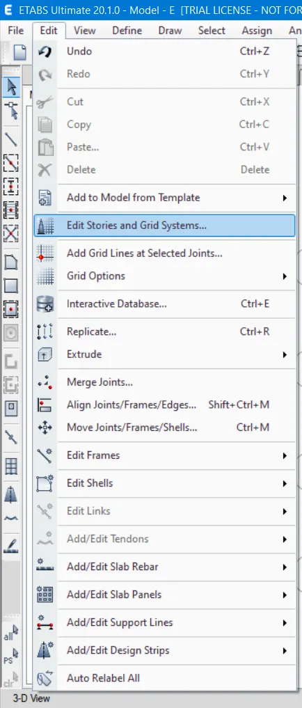
- For that Click and select Edit < Edit Stories and Grid Systems < Edit story and Grid System Data Tab will be opened.
- From the Tab opened Click and select Modify/show story Data < Stroy Data .
- In story data right click above the existing created last story and select Add story < Keep Existing Story Heights .
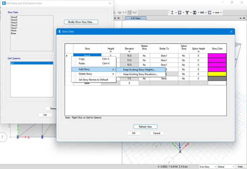
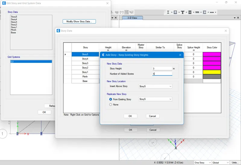
- Then a new tab will be opened in the name of Add story - Keep existing story heights.
- From Add stroy < New Story Data < Story Height = 3m, Number of Added Stories = 5 and click OK to get total of 10 Stories.
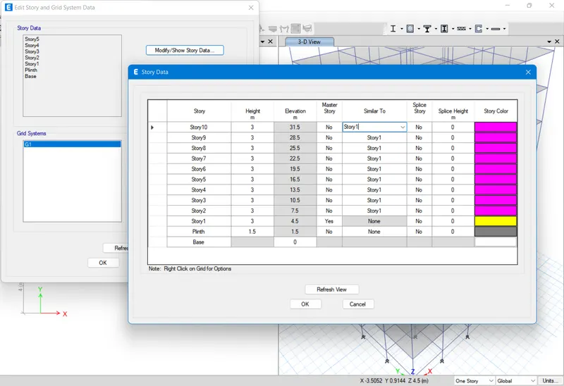
- After adding the additional 5 stories we get total of 10 Stories and change the 'Similar To' for those added stories as Story 1.
- Here in this Model - E, the Column sizes should be change from C550x300 to C600X600 for storey 1 to storey 5 as per required.
- For that select Define < Section properties < Frame sections.
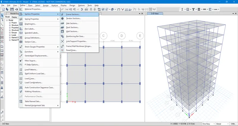
- After that the Frame properties Tab will be opened, in it select existing C550x300 and click Modify/Show Property.
- Then the Frame Section property Data Tab will be opened, here change the Property Name = C600x600, Depth = 600, Width = 600 and click OK.
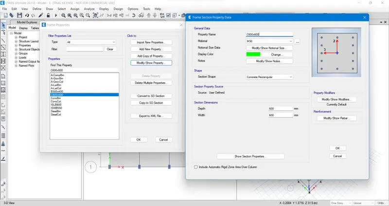
- Then to create a New Column sizes for Storey 1 to storey 5, select the Frame properties Tab < Add New Property = Concrete (Rectangular section) and click OK.
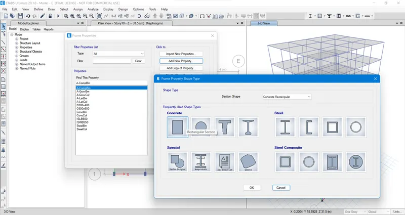
- After selecting the Rectangular section (concrete), a New tab will be opened in the name of Frame Section Property Data .
- From Frame Section Property Data Tab in General Data < Property Name = C400x400, Material = M30 and in Section Dimensions < Depth = 400mm, Width = 400mm and click OK.
- Followed by select Modify/show Rebar < Frame Section property Reinforcement Data Tab will be opened.
- From the opened Tab be sure that the following options are selected correctly.
- The followings such as P=M2-M3 Design (column) and Longitudinal Bars = HYSD415, Confinements bars (Ties) = HYSD415 and click OK.
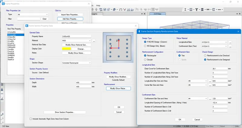
- Atlast assign the Created various sizes of columns into the appropriate stories of the Building - E.
- Before that the remaining structures other than Columns has to be made invisible from the Workspace windows.
- To make the structures other than Columns into invisible from the Workspace select and click Set display Options and Un-tick the check Box of Beams and Floors options.
- Now we can see only the column structures in the workspace.
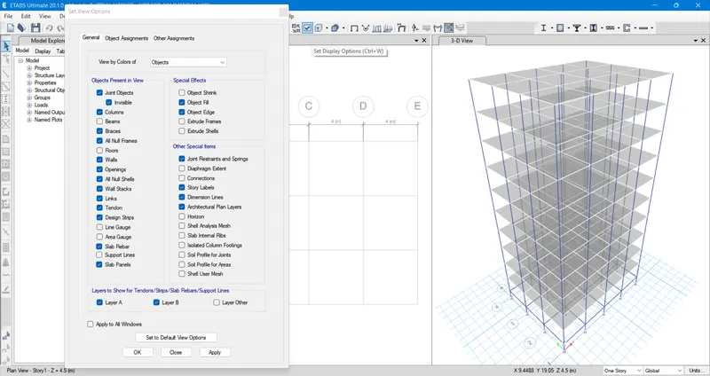
- To apply the column sized 400x400 for the Storey 6 to Storey 10, those stories should be viewed separately in the window.
- For that click and select View < Set building View Limits then the Set Building View Limits Tab will be opened.
- Here in Set Story Range < Top Story = Story 10, Bottom Story = Story 6 and click OK.
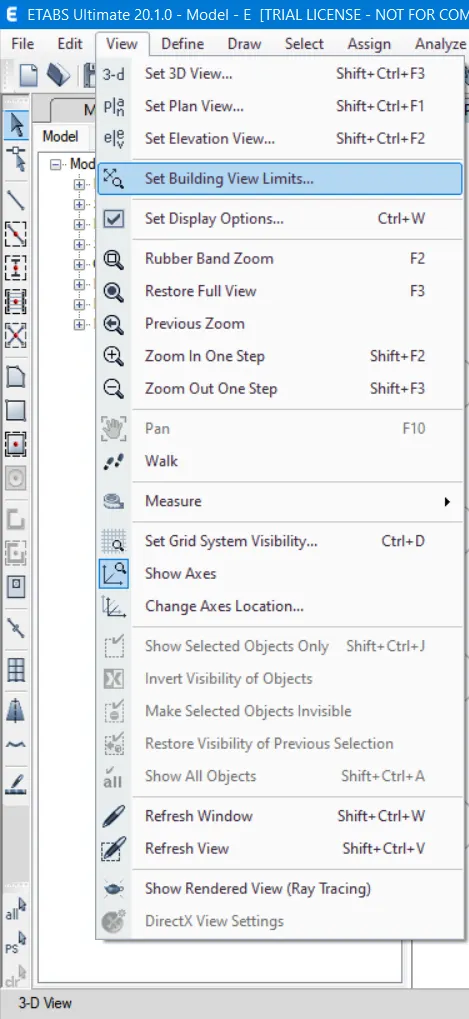
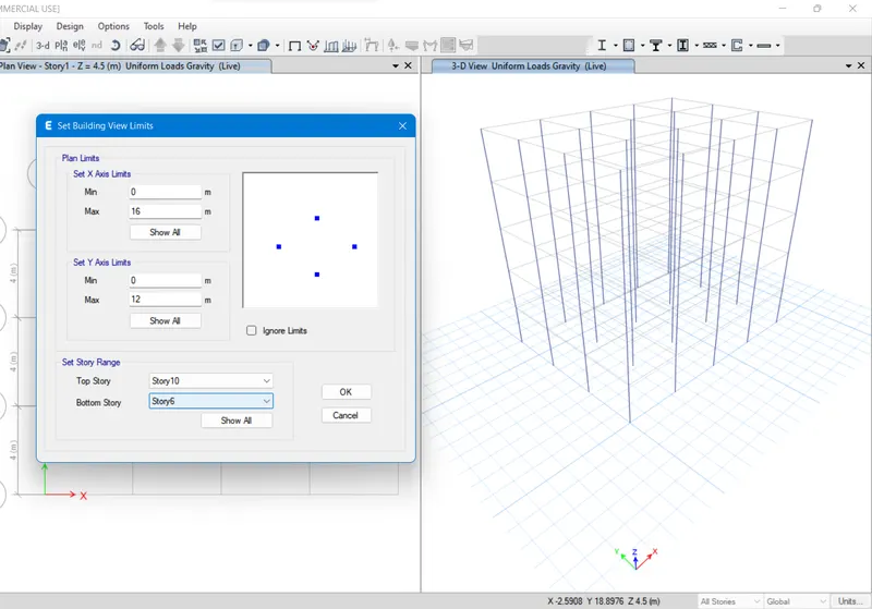
- After Separating the Columns for Storey 6 to Storey 10, click and select all the visible columns by window selection.
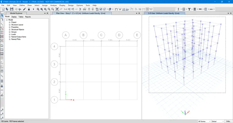
- After selecting all the columns of the Storey 6 to Storey 10 , Assign the appropriate column size.
- It has to be done by Select Assign < Frame < Section Property < Frame Assignment - Section Property Tab will be opened.
- From the opened Tab Select the column size C400x400 and click Apply to assign the column to the selected Storey 6 to 10.
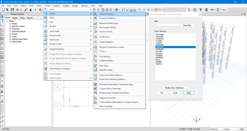
- Now we can change the whole stories of the Building from Base to Storey 10.
- For that click and select View < Set building View Limits then the Set Building View Limits Tab will be opened.
- Here in Set Story Range < Top Story = Story 10, Bottom Story = Base and click OK.
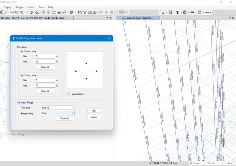
- And now the remaining structures other than Columns has to be made visible to the Workspace windows.
- To make the structures other than Columns visible to the Workspace, select and click Set display Options and tick the check Box of Beams and Floors options.
- Now we can see all the structures of the Building - E in the workspace.
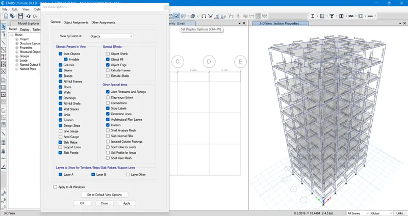
- Then check whether the applied Superdead load for Beams upto the story 10.
- For that Click the Display Frame Load Assigns option in the Tool bar above Workspace.
- The show frame loads Tab will be opened.
- In the opened tab select Load pattern = BrickWall and click OK to see the applied Superdead load of 10kN over all Beams.
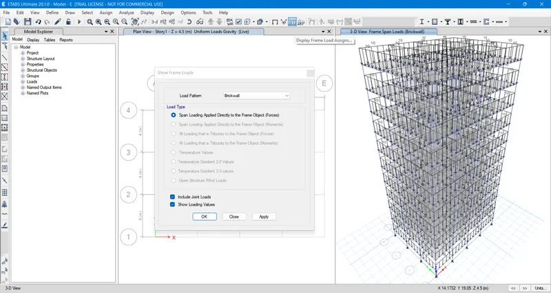
- Likewise check whether the applied Live load for Slabs upto the story 10.
- For that Click the Display Shell Load Assigns option in the Tool bar above Workspace.
- The Show Shell loads Tab will be opened.
- In the opened tab select Load pattern = Live and click OK to see the applied Live load of 3kN over all Slabs.
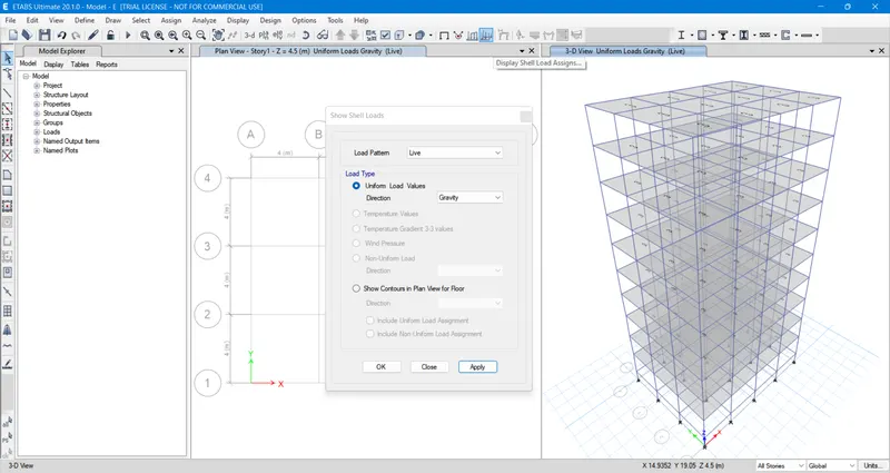
- Then select all assigned Slabs by clicking Select < Properties < Slab sections < Select by Slab property Tab < Slab150.
- After selecting Slab150 Slab, click Select to select all the Slabs assigned to the Building Model - E.
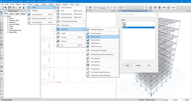
- Then assign Shell Diaphragms to the selected 150mm slab.
- For that click Assign < Shell < Diaphragms < D1 and click Apply.
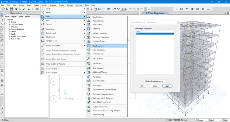
- After the assigning of the Diaphragms, we can Run Analysis from the option given in the tool bar.
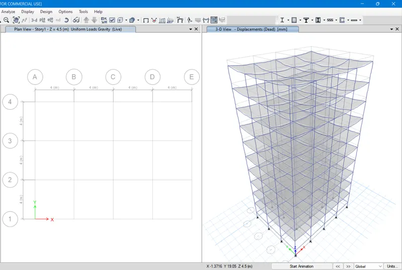
- After the completion of the analysis, the Deformed shape of the Building will be visible in 3D view Window.
- We can see the Analysis Result from the Table option below the Model Explorer Window at the left side of the workspace.
- Atlast save the created Model - E from File < Save.
6. BUILDING - F (10 STOREY BUILDING)
- After saving the Model - E, from the same file click File < Save as and save the file as Model - F.
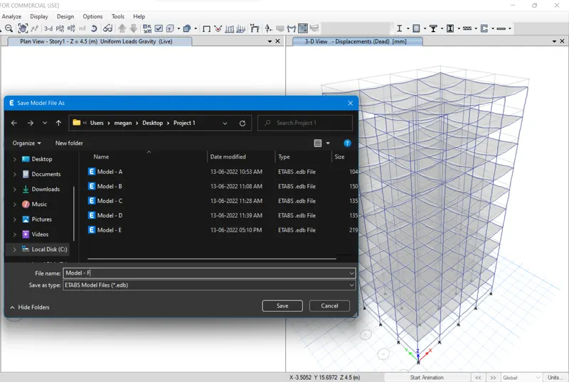
- Here in Building - F all the column sizes should be assigned as C600x600 from Base to Storey 10 as required.
- So the remaining structures other than Columns should be made invisible from the Workspace windows to select all columns easily.
- To make the structures other than Columns into invisible from the Workspace, select and click Set display Options and Un-tick the check Box of Beams and Floors options.
- Now we can see only the column structures in the workspace from Base to storey 10.
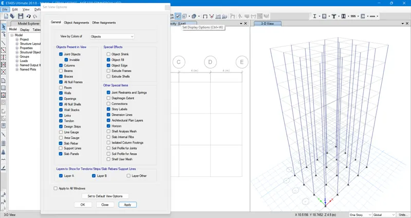
- To apply the column sized 600x600 for the Storey 6 to Storey 10, those stories should be viewed separately in the window.
- For that click and select View < Set building View Limits then the Set Building View Limits Tab will be opened.
- Here in Set Story Range < Top Story = Story 10, Bottom Story = Story 6 and click OK.
- After Separating the Columns for Storey 6 to Storey 10, click and select all the visible columns by window selection.
- After selecting all the columns of the Storey 6 to Storey 10 , Assign the appropriate column size.
- It has to be done by Select Assign < Frame < Section Property < Frame Assignment - Section Property Tab will be opened.
- From the opened Tab Select the column size C600x600 and click Apply to assign the column to the selected Storey 6 to 10.
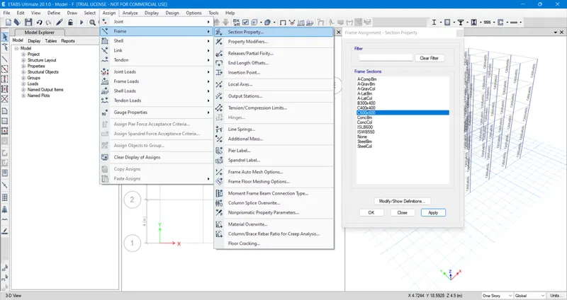
- Now we can change the whole stories of the Building from Base to Storey 10.
- For that click and select View < Set building View Limits then the Set Building View Limits Tab will be opened.
- Here in Set Story Range < Top Story = Story 10, Bottom Story = Base and click OK.
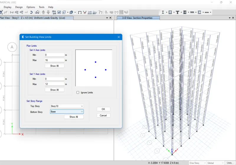
- And now the remaining structures other than Columns has to be made visible to the Workspace windows.
- To make the structures other than Columns visible to the Workspace, select and click Set display Options and tick the check Box of Beams and Floors options.
- Now we can see all the structures of the Building - F in the workspace.
- Then check whether the applied Superdead load for Beams upto the story 10.
- For that Click the Display Frame Load Assigns option in the Tool bar above Workspace.
- The show frame loads Tab will be opened.
- In the opened tab select Load pattern = BrickWall and click OK to see the applied Superdead load of 10kN over all Beams.
- Likewise check whether the applied Live load for Slabs upto the story 10.
- For that Click the Display Shell Load Assigns option in the Tool bar above Workspace.
- The Show Shell loads Tab will be opened.
- In the opened tab select Load pattern = Live and click OK to see the applied Live load of 3kN over all Slabs.
- Then select all assigned Slabs by clicking Select < Properties < Slab sections < Select by Slab property Tab < Slab150.
- After selecting Slab150 Slab, click Select to select all the Slabs assigned to the Building Model - F.
- Then assign Shell Diaphragms to the selected 150mm slab.
- For that click Assign < Shell < Diaphragms < D1 and click Apply.
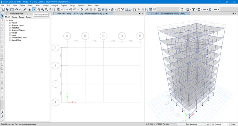
- After the assigning of the Diaphragms, we can Run Analysis from the option given in the tool bar.
- After the completion of the analysis, the Deformed shape of the Building will be visible in 3D view Window.
- We can see the Analysis Result from the Table option below the Model Explorer Window at the left side of the workspace.
- Atlast save the created Model - F from File < Save.
7. BUILDING - G (25 - STOREY BUILDING WITH VARYING COLUMN SIZES ALONG BUILDING HEIGHT)
- After saving the Model - F, from the same file click File < Save as and save the file as Model - G.
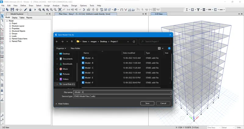
- Here in this Model - G, a Column sizes should be created as C800X800 for Bottom 10 storeys as per required.
- For that select Define < Section properties < Frame sections < Frame Properties Tab will be opened.
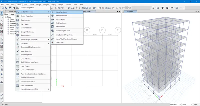
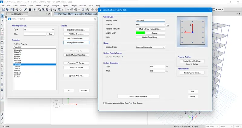
- After that the Frame properties Tab will be opened, in it select existing C600x600 and click Modify/Show Property.
- Then the Frame Section property Data Tab will be opened, here change the Property Name = C800x800, Depth = 800, Width = 800 and click OK.
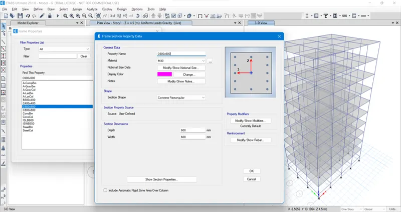
- Then to create a New Column sizes for Middle 10 Storeys, select the Frame properties Tab < Add New Property = Concrete (Rectangular section) and click OK.
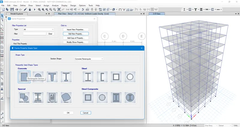
- After selecting the Rectangular section (concrete), a New tab will be opened in the name of Frame Section Property Data .
- From Frame Section Property Data Tab in General Data < Property Name = C600x600, Material = M30 and in Section Dimensions < Depth = 600mm, Width = 600mm and click OK.
- Followed by select Modify/show Rebar < Frame Section property Reinforcement Data Tab will be opened.
- From the opened Tab be sure that the following options are selected correctly.
- The followings such as P=M2-M3 Design (column) and Longitudinal Bars = HYSD415, Confinements bars (Ties) = HYSD415 and click OK.
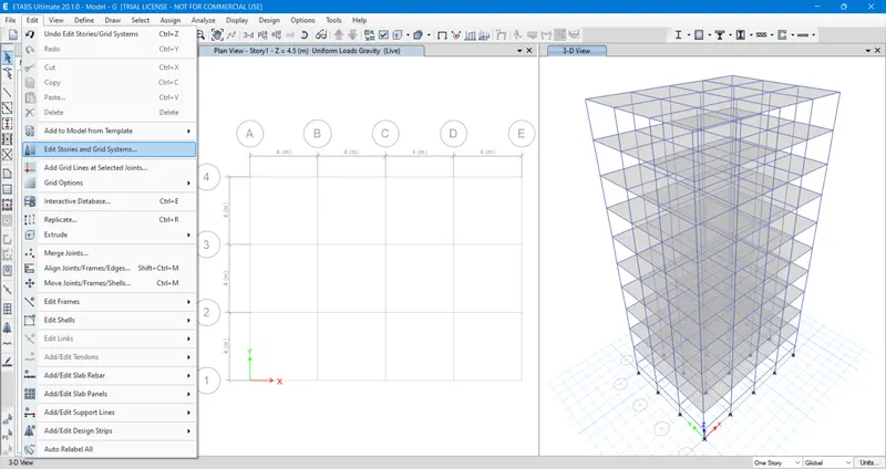
- Then edit the Strories and grids as per the Building - G requirement.
- For that Click and select Edit < Edit Stories and Grid Systems < Edit story and Grid System Data Tab will be opened.
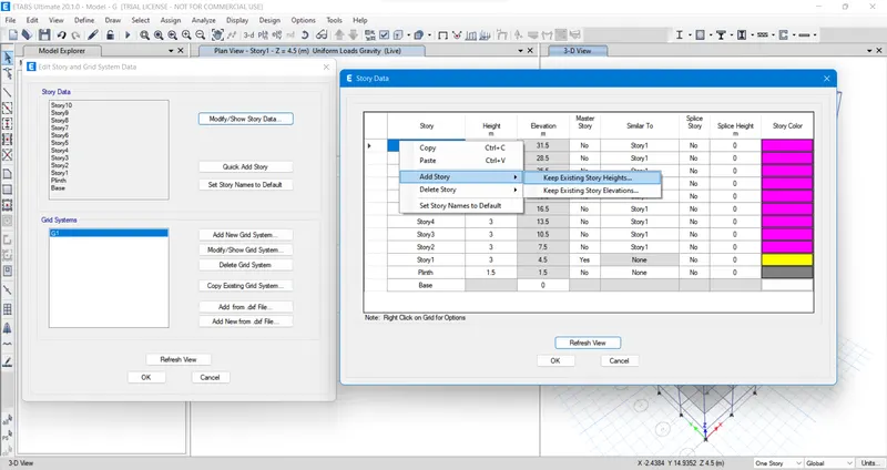
- From the Tab opened Click and select Modify/show story Data < Stroy Data .
- In story data right click above the existing created last story and select Add story < Keep Existing Story Heights .
- Then a new tab will be opened in the name of Add story - Keep existing story heights.
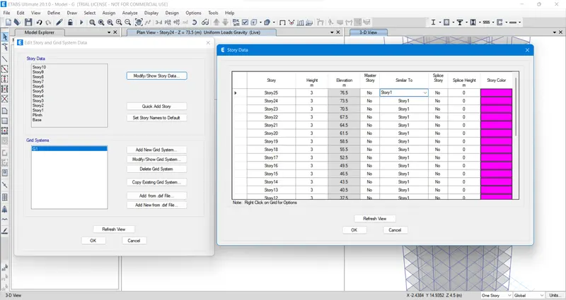
- From Add stroy < New Story Data < Story Height = 3m, Number of Added Stories = 15 and click OK .
- After adding the additional 15 stories we get total of 25 Stories and change the Similar To for those added stories as Story 1.
- Now to assign the Created various sizes of columns into the appropriate stories of the Building - G.
- Before that the remaining structures other than Columns has to be made invisible from the Workspace windows.
- To make the structures other than Columns into invisible from the Workspace select and click Set display Options and Un-tick the check Box of Beams and Floors options.
- Now we can only see the column structures in the workspace.
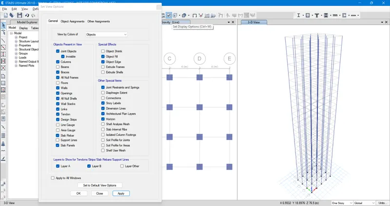
- To apply the column sized 400x400 for the Storey 21 to Storey 25, those stories should be viewed separately in the window.
- For that click and select View < Set building View Limits then the Set Building View Limits Tab will be opened.
- Here in Set Story Range < Top Story = Story 25, Bottom Story = Story 21 and click OK.
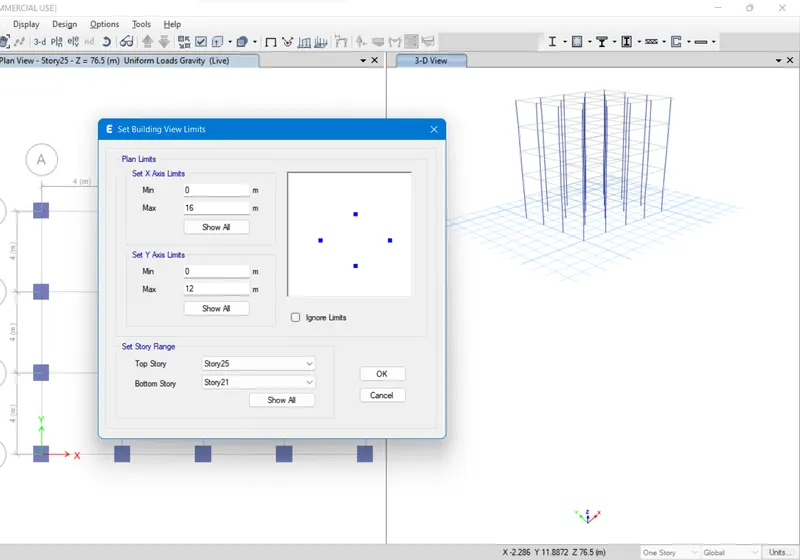
- After Separating the Columns for Storey 21 to Storey 25, click and select all the visible columns by window selection.
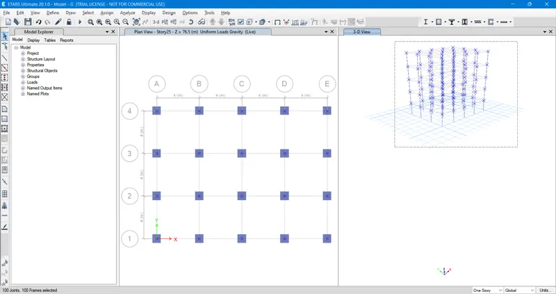
- After selecting all the columns of the Storey 21 to Storey 25 , Assign the appropriate column size.
- It has to be done by Select Assign < Frame < Section Property < Frame Assignment - Section Property Tab will be opened.
- From the opened Tab Select the column size C400x400 and click Apply to assign the column to the selected Storey 21 to 25.
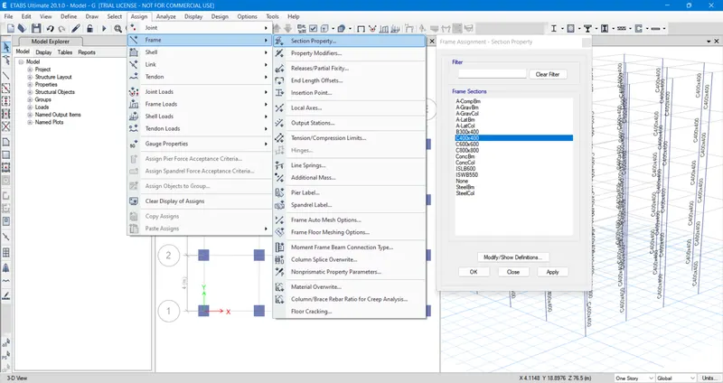
- To apply another column sized 600x00 for the Storey 11 to Storey 20, those stories should be viewed separately in the window.
- For that click and select View < Set building View Limits then the Set Building View Limits Tab will be opened.
- Here in Set Story Range < Top Story = Story 20, Bottom Story = Story 11 and click OK.
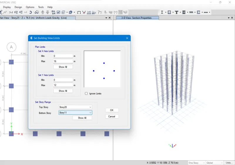
- After Separating the Columns for Storey 11 to Storey 20, click and select all the visible columns by window selection.
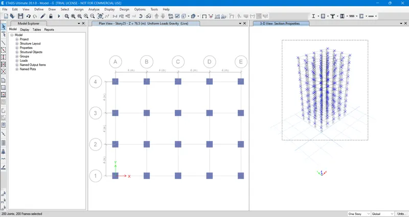
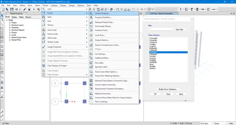
- After selecting all the columns of the Storey 11 to Storey 20 , Assign the appropriate column size.
- It has to be done by Select Assign < Frame < Section Property < Frame Assignment - Section Property Tab will be opened.
- From the opened Tab Select the column size C600x600 and click Apply to assign the column to the selected Storey 11 to 20.
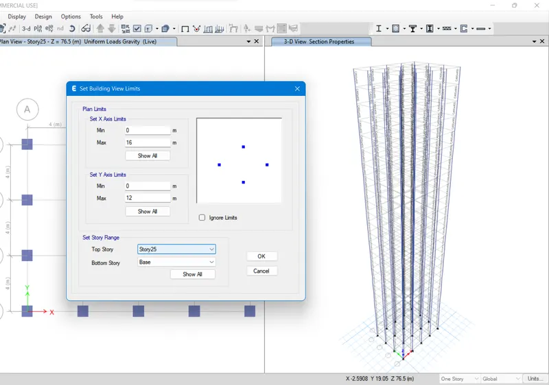
- Now we can change the whole stories of the Building from Base to Storey 25.
- For that click and select View < Set building View Limits then the Set Building View Limits Tab will be opened.
- Here in Set Story Range < Top Story = Story 25, Bottom Story = Base and click OK.
- And now the remaining structures other than Columns has to be made visible to the Workspace windows.
- To make the structures other than Columns visible to the Workspace, select and click Set display Options and tick the check Box of Beams and Floors options.
- Now we can see all the structures of the Building - G in the workspace.
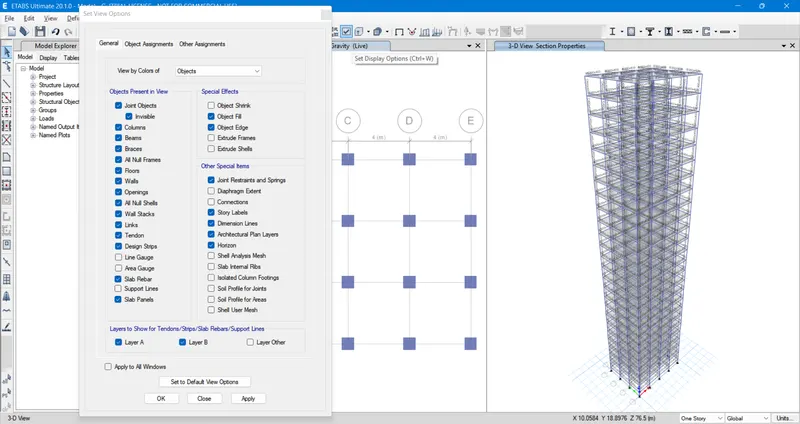
- Then check whether the applied Superdead load for Beams upto the story 25.
- For that Click the Display Frame Load Assigns option in the Tool bar above Workspace.
- The show frame loads Tab will be opened.
- In the opened tab select Load pattern = BrickWall and click OK to see the applied Superdead load of 10kN over all Beams.
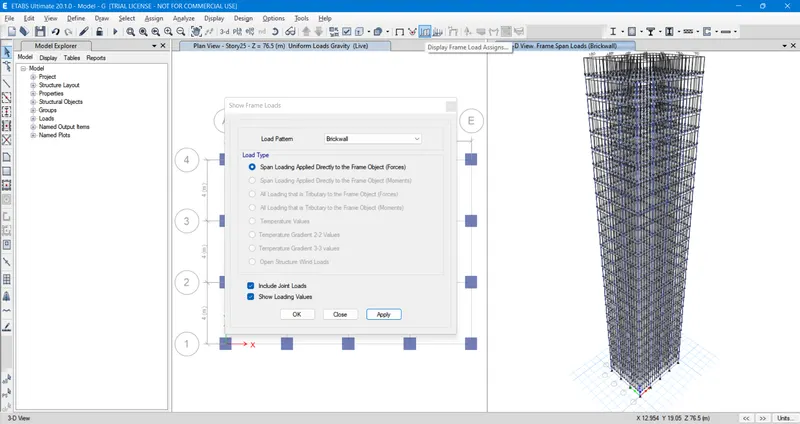
- Likewise check whether the applied Live load for Slabs upto the story 25.
- For that Click the Display Shell Load Assigns option in the Tool bar above Workspace.
- The Show Shell loads Tab will be opened.
- In the opened tab select Load pattern = Live and click OK to see the applied Live load of 3kN over all Slabs.
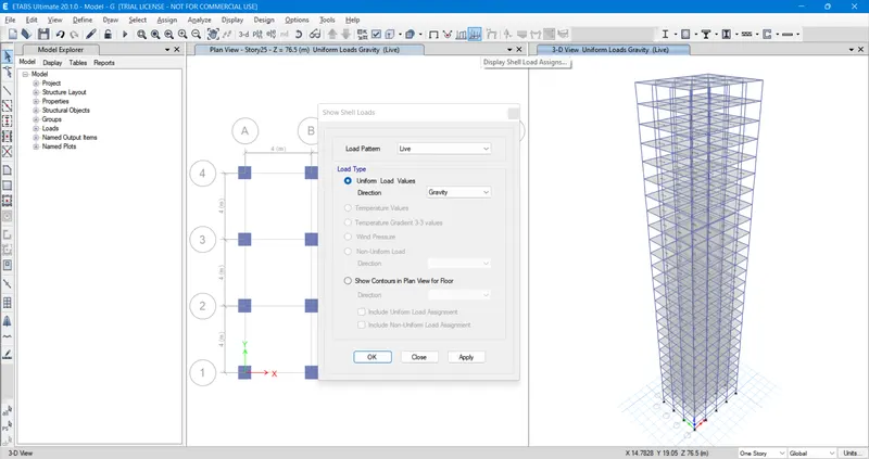
- Then select all assigned Slabs by clicking Select < Properties < Slab sections < Select by Slab property Tab < Slab150.
- After selecting Slab150 Slab, click Select to select all the Slabs assigned to the Building Model - G.
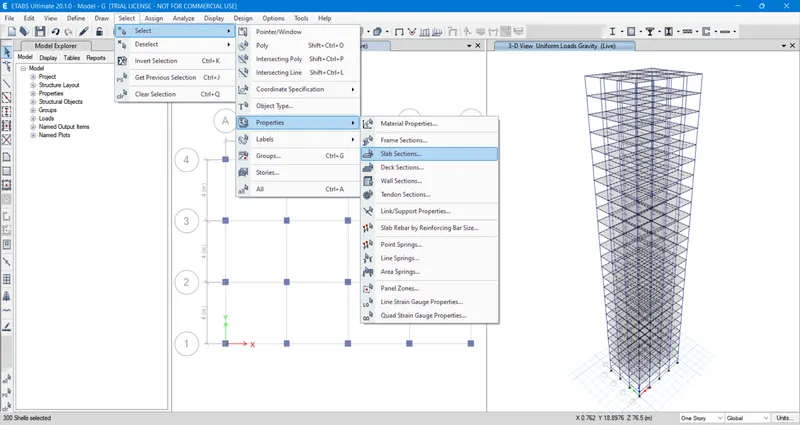
- Then assign Shell Diaphragms to the selected 150mm slab.
- For that click Assign < Shell < Diaphragms < D1 and click Apply.
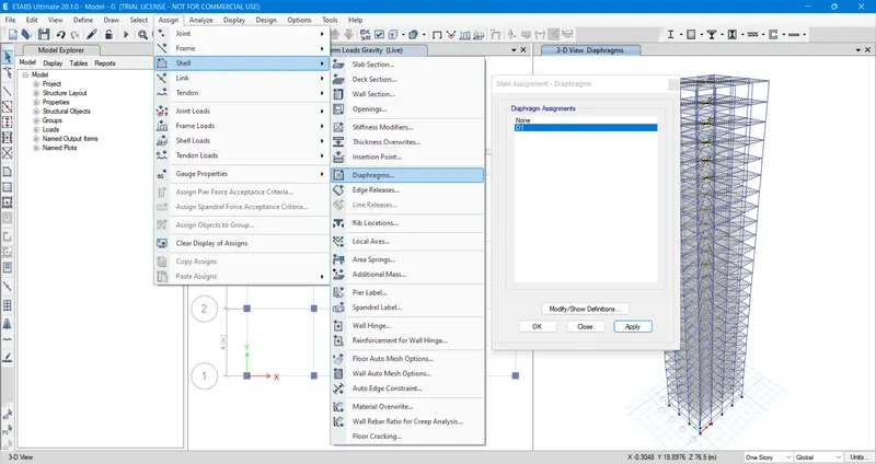
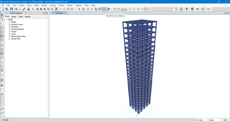
Too see the Extruded View of the Whole Structures of the 25 Storey Model, click the Option Extruded View Toggle option present at the Tool Bar.
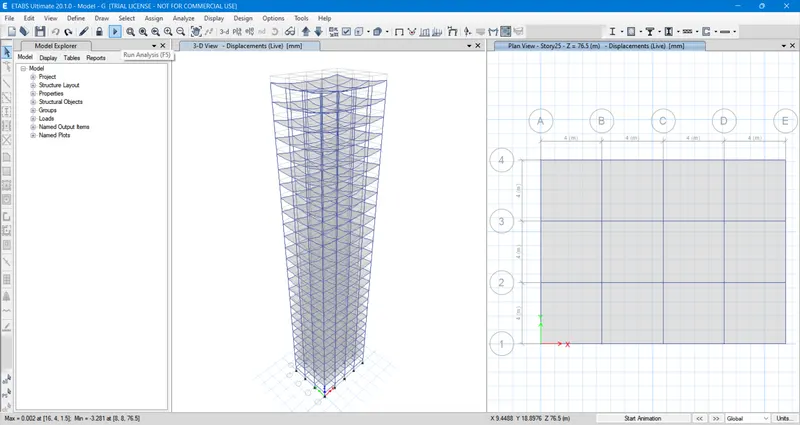
- After the assigning of the Diaphragms, we can Run Analysis from the option given in the tool bar.
- After the completion of the analysis, the Deformed shape of the Building will be visible in 3D view Window.
- We can see the Analysis Result from the Table option below the Model Explorer Window at the left side of the workspace.
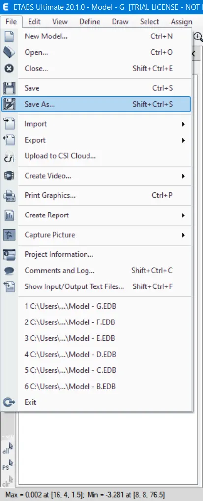
- Atlast save the created Model - G from File < Save.
8. BUILDING - H (25 STOREY BUILDING)
- After saving the Model - G, from the same file click File < Save as and save the file as Model - H.
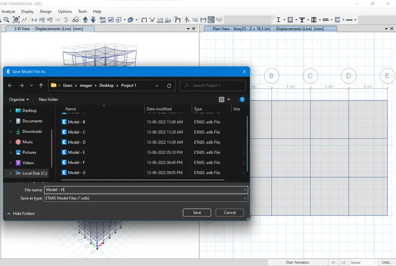
- Here in Building - H all the column sizes should be assigned as C800x800 from Base to Storey 25 as required.
- So the remaining structures other than Columns should be made invisible from the Workspace windows to select all columns easily.
- To make the structures other than Columns into invisible from the Workspace, select and click Set display Options and Un-tick the check Box of Beams and Floors options.
- Now we can see only the column structures in the workspace from Base to storey 25.
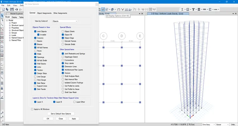
- After making the structures invisible other than Columns, click and select all the visible columns by window selection.
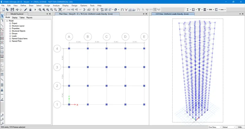
- After selecting all the columns of the BUILDING MODEL - H, Assign the appropriate column size.
- It has to be done by Select Assign < Frame < Section Property < Frame Assignment - Section Property Tab will be opened.
- From the opened Tab Select the column size C800x800 and click Apply to assign the column size to all the selected Columns.
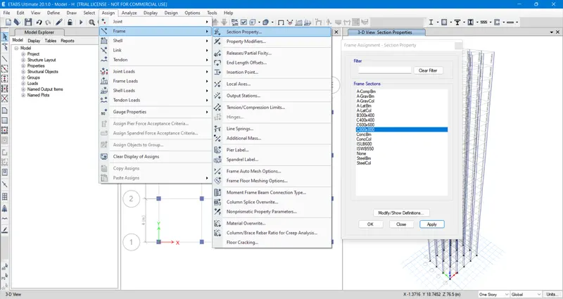
- And now the remaining structures other than Columns has to be made visible to the Workspace windows.
- To make the structures other than Columns visible to the Workspace, select and click Set display Options and tick the check Box of Beams and Floors options.
- Now we can see all the structures of the Building - H in the workspace.
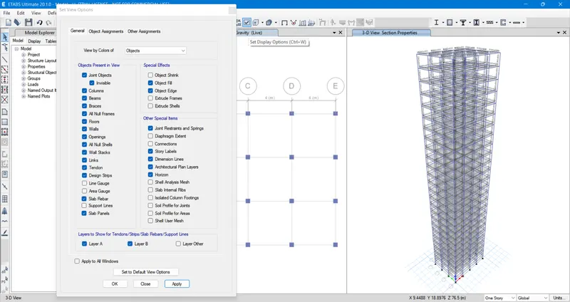
- Then check whether the applied Superdead load for Beams upto the story 25.
- For that Click the Display Frame Load Assigns option in the Tool bar above Workspace.
- The show frame loads Tab will be opened.
- In the opened tab select Load pattern = BrickWall and click OK to see the applied Superdead load of 10kN over all Beams.
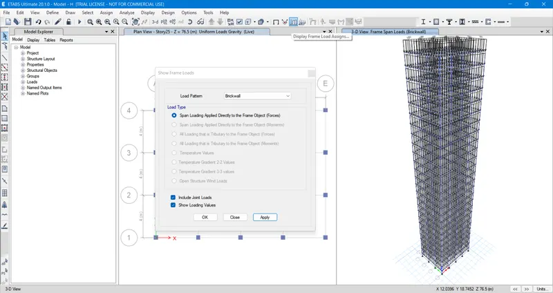
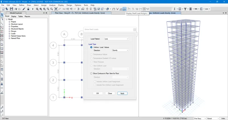
- Likewise check whether the applied Live load for Slabs upto the story 25.
- For that Click the Display Shell Load Assigns option in the Tool bar above Workspace.
- The Show Shell loads Tab will be opened.
- In the opened tab select Load pattern = Live and click OK to see the applied Live load of 3kN over all Slabs.
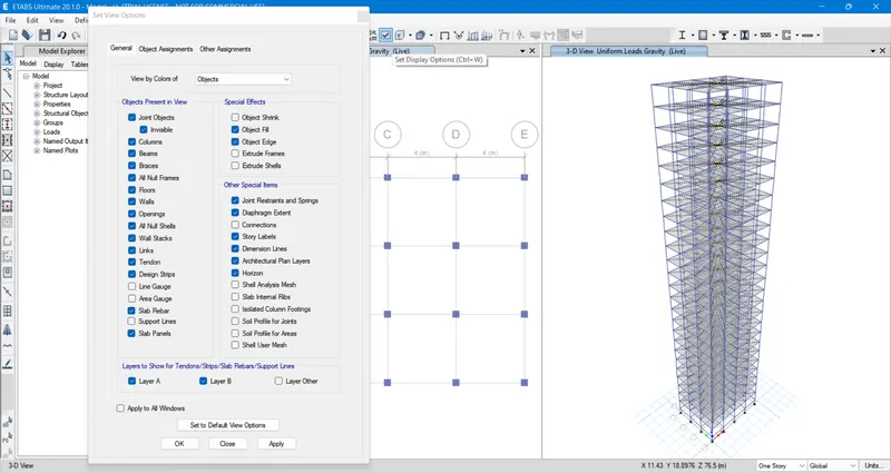
- We can Set the Diaphragm of the Slabs as Defaultly applied by Selecting Set Display Options on the Tool Bar.
- After clicking the Set View Option Tab will be opened, from there Tick the check Box of the Diaphragm Extent below other special Items.
- After the assigning of the Diaphragms, we can Run Analysis from the option given in the tool bar.
- After the completion of the analysis, the Deformed shape of the Building will be visible in 3D view Window.
- We can see the Analysis Result from the Table option below the Model Explorer Window at the left side of the workspace.
- Atlast save the created Model - H from File < Save.
9. BUILDING - J : (25 - STOREY BUILDING WITH IMPOSED MASS 10% LARGER THAN BUILDING H )
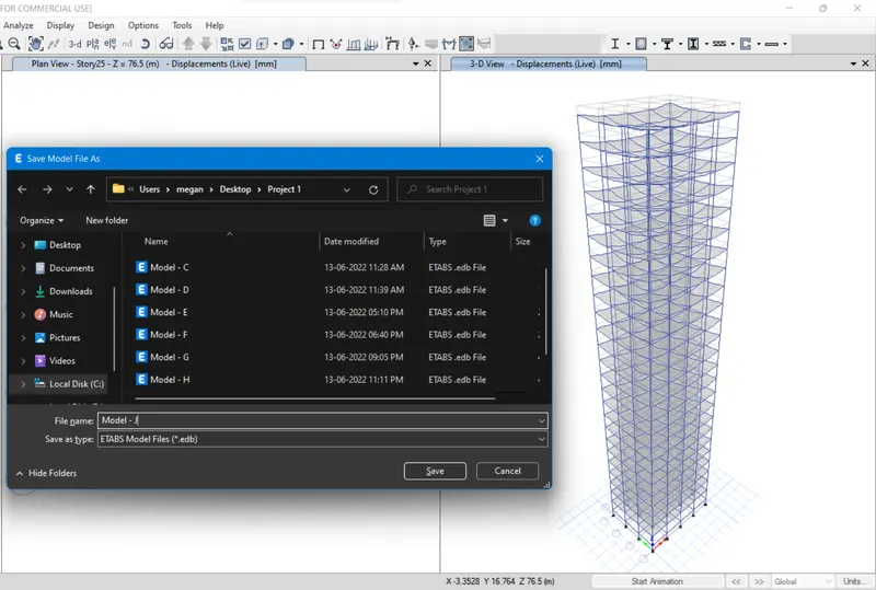
- After saving the Model - H, from the same file click File < Save as and save the file as Model - J.
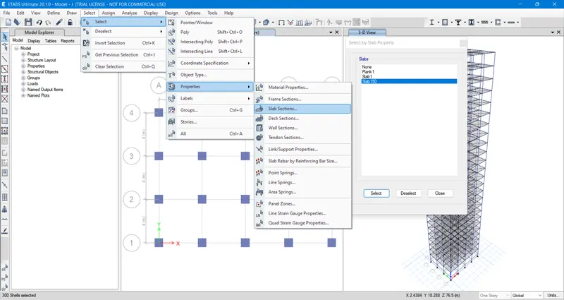
- Now select all assigned Slabs by clicking Select < Properties < Slab sections < Select by Slab property Tab < Slab150.
- After selecting Slab150 Slab, click Select to select all the Slabs assigned to the Building Model - J.
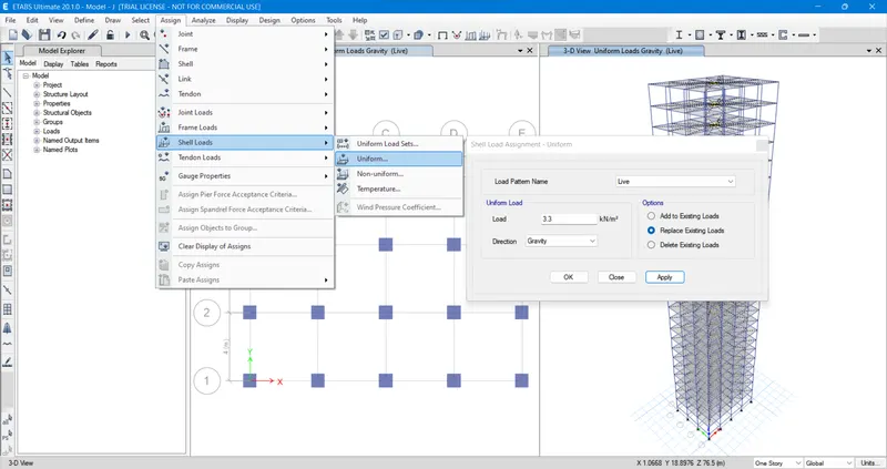
- Then apply Imposed load 10% larger than 'Building - H' Slabs by clicking Assign < Shell loads < uniform < Shell Load Assignment - Uniform Tab.
- From the Shell Load Assignment - Uniform Tab < Load Pattern Name = Live, Uniform Load = 3.3 kN/m^3 and click Apply.
- After the assigning of the Imposed load, we can Run Analysis from the option given in the tool bar.
- After the completion of the analysis, the Deformed shape of the Building will be visible in 3D view Window.
- We can see the Analysis Result from the Table option below the Model Explorer Window at the left side of the workspace.
- Atlast save the created Model - J from File < Save.
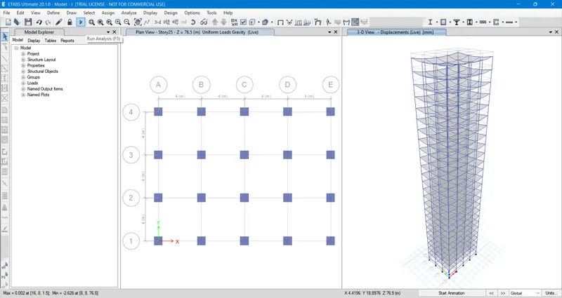
10. BUILDING - K : (25 - STOREY BUILDING WITH IMPOSED MASS 10% LARGER THAN BUILDING H )
- After saving the Model - J, from the same file click File < Save as and save the file as Model - K.
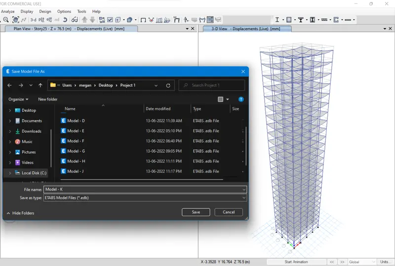
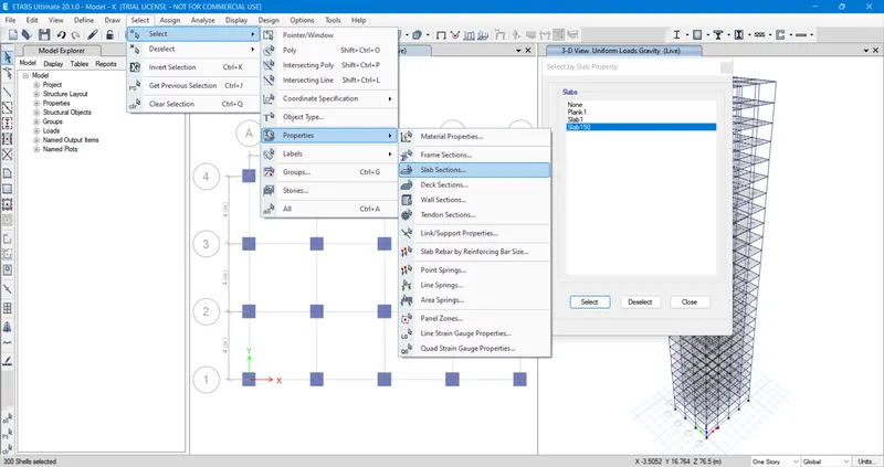
- Now select all assigned Slabs by clicking Select < Properties < Slab sections < Select by Slab property Tab < Slab150.
- After selecting Slab150 Slab, click Select to select all the Slabs assigned to the Building Model - K.
- Then apply Imposed load 20% larger than 'Building - H' Slabs by clicking Assign < Shell loads < uniform < Shell Load Assignment - Uniform Tab.
- From the Shell Load Assignment - Uniform Tab < Load Pattern Name = Live, Uniform Load = 3.6 kN/m^3 and click Apply.
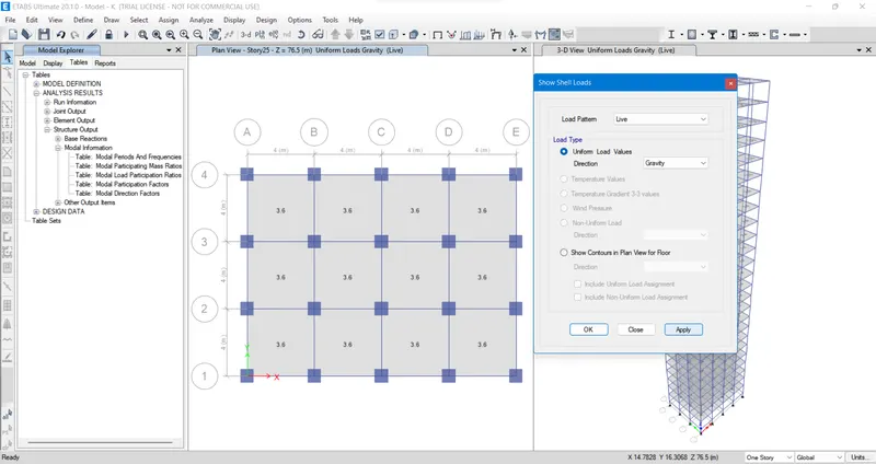
- After the assigning of the Imposed load, we can Run Analysis from the option given in the tool bar.
- After the completion of the analysis, the Deformed shape of the Building will be visible in 3D view Window.
- We can see the Analysis Result from the Table option below the Model Explorer Window at the left side of the workspace.
- Atlast save the created Model - K from File < Save.
RESULT :
|
SI. NO |
CRITERIA |
MODEL |
ANALYSIS RESULT |
CONCLUSION |
|
1. |
Effect of stiffness on time period. |
Building – E (10 storey with varying column size). |
1.73 sec |
Safe |
|
Building – F (10 storey with uniform column size). |
1.73 sec |
|||
|
Effect of stiffness on time period. |
Building – G (25 storey with varying column size). |
4.17 sec |
Safe |
|
|
Building – H (25 storey with uniform column size). |
4.41 sec |
|||
|
2. |
Effect of mass on time period. |
Building – H (25 storey with 3 kN/sq.m imposed load). |
4.41 sec |
Safe |
|
Building – J (25 storey with 3.3 kN/sq.m imposed load). |
4.42 sec |
|||
|
Building – K (25 storey with 3.6 kN/sq.m imposed load). |
4.43 sec |
Safe |
||
|
3. |
Effect of building height on time period. |
Building – A (2 storey) |
0.5 sec |
Safe |
|
Building – B (2 storey) |
1.03 sec |
Safe |
||
|
Building – F (2 storey) |
1.73 sec |
Safe |
||
|
Building – H (2 storey) |
4.41 sec |
Dangerous |
||
|
4. |
Effect of column orientation on time period. |
Building – B (All floors column size 400x400 ) |
1.03 sec |
Safe |
|
Building – C (All floors column size 550x300 ) oriented in X-direction. |
1.14 sec |
Safe |
||
|
Building – D (All floors column size 300x550 ) oriented in Y-direction. |
1.12 sec |
Safe |
||
|
5. |
Effect of axial stiffness of vertical members on mode shapes. |
Building - H |
Axial cross section for columns is close to nil (Zero axial area) |
5.99 sec |
Very Dangerous |
|
Full Axial cross section for columns (Regular) |
4.41 sec |
Dangerous |
|
6. |
Effect of flexural stiffness of structural element on mode shapes. |
Building - B |
Flexural stiffness of beams close to nil (Zero inertia) |
2.62 sec |
Dangerous |
|
Full flexural stiffness of beams (Regular) |
1.03 sec |
Safe |
|
7. |
Effect of degree of fixity at column base on mode shapes. |
Building - B |
Column support pinned (Regular) |
1.03 sec |
Safe |
|
Column support fixed |
0.941 sec |
Safe |
1. ) EFFECT OF STIFFNESS ON TIME PERIOD :
1 a) BUILDING E : (10 STOREY WITH VARYING COLUMN SIZES)
- Open a Etabs software then click and select already created Model E file displaying in the Recent Models.
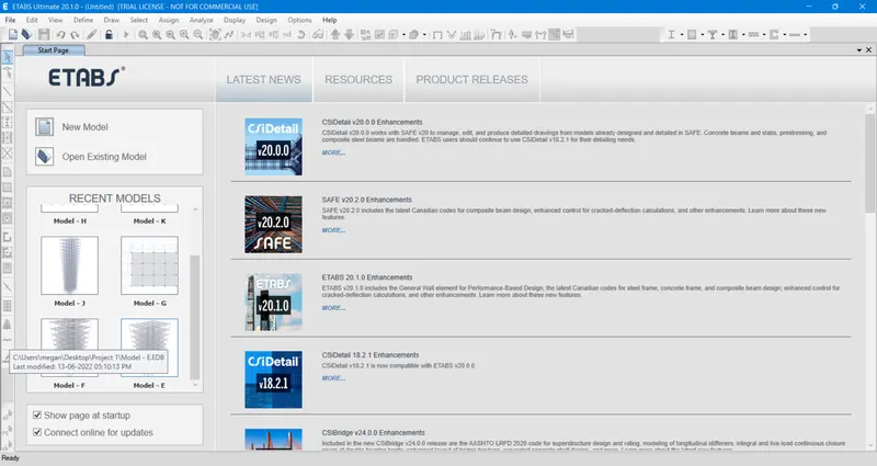
- After selecting and opening of the Model E, try to open the Analysed Result Table.
- For that from the Model Explorer Window select Table < Analysis Results < Model Information < Table - Model Periods and Frequencies.
- Then Right click over the Table - Model Periods and Frequencies and select Show Table.
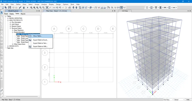
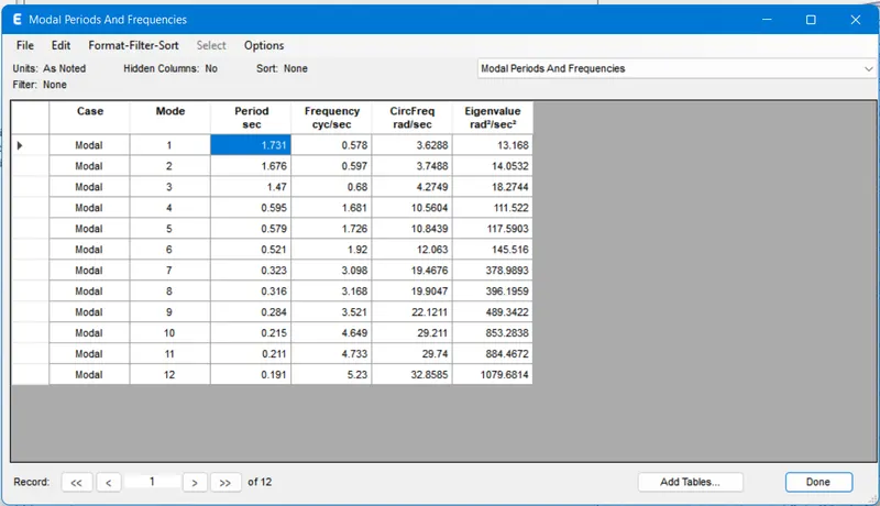
- A New Tab will be opened after selecting Show table named Model Periods and Frequencies.
- Here we can see the Modal 1's Periodic second = 1.731 and we can note it down in the Result Table as required.
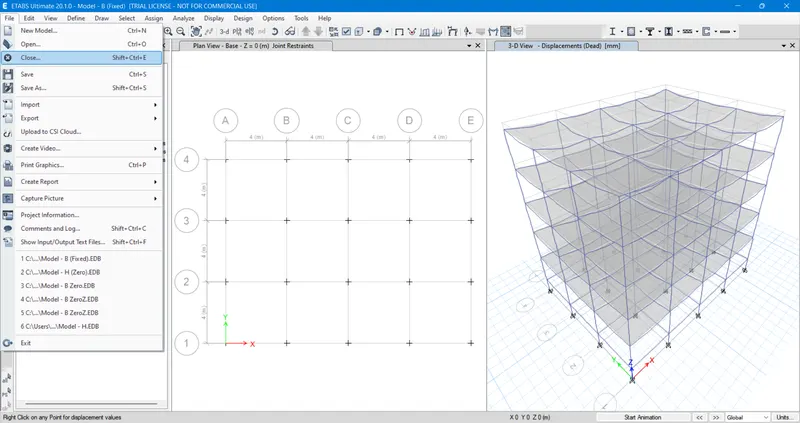
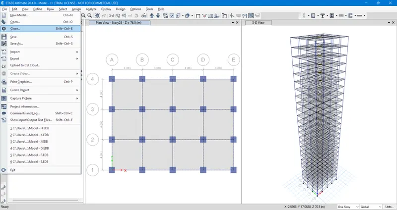
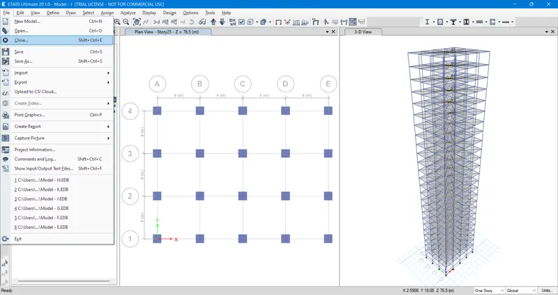
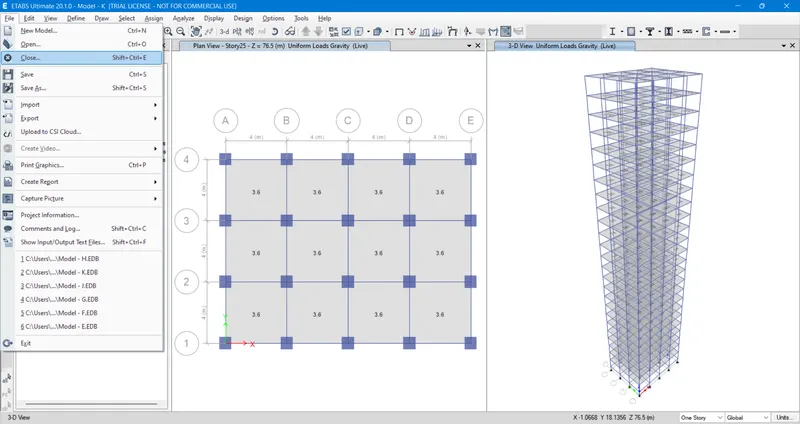
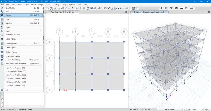
- Atlast we can close the opened Model - E file by selecting File < Close.
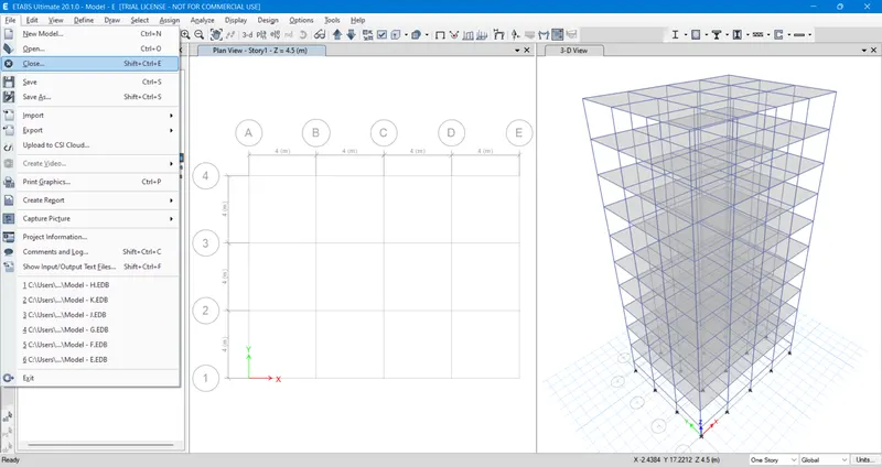
1 b) BUILDING F : (10 STOREY WITH UNIFORM COLUMN SIZES)
- After closing the Model - E by File < Close, Now click and select the created Model F file displaying in the Recent Models.
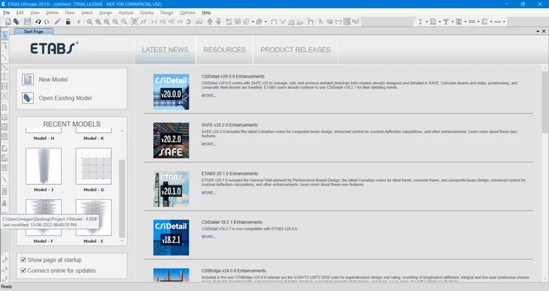
- After selecting and opening of the Model F, try to open the Analysed Result Table.
- For that from the Model Explorer Window select Table < Analysis Results < Model Information < Table - Model Periods and Frequencies.
- Then Right click over the Table - Model Periods and Frequencies and select Show Table.
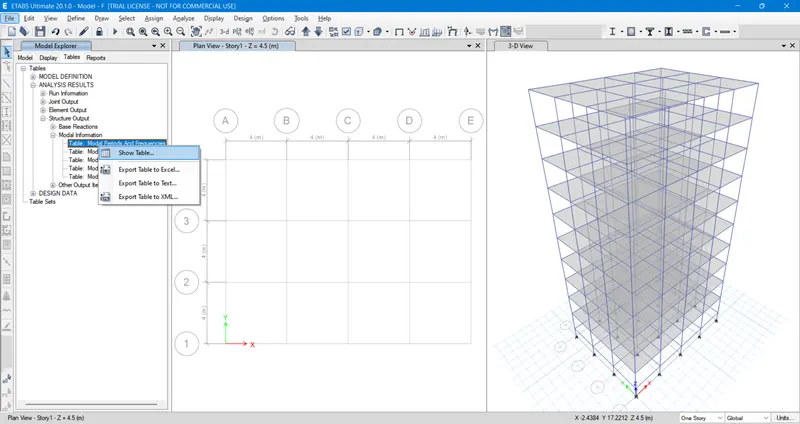
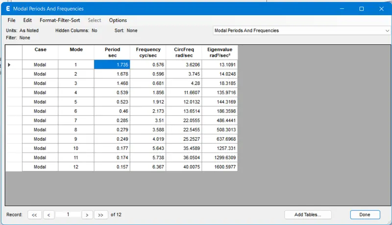
- A New Tab will be opened after selecting Show table named Model Periods and Frequencies.
- Here we can see the Modal 1's Periodic second = 1.735 and we can note it down in the Result Table as required.
- Now close the opened Model - E file by selecting File < Close to open next file from the Home.
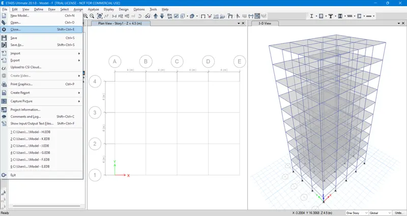
1 c) BUILDING G : (25 STOREY WITH VARYING COLUMN SIZES)
- After closing the Model - F by File < Close, Now click and select the created Model G file displaying in the Recent Models.
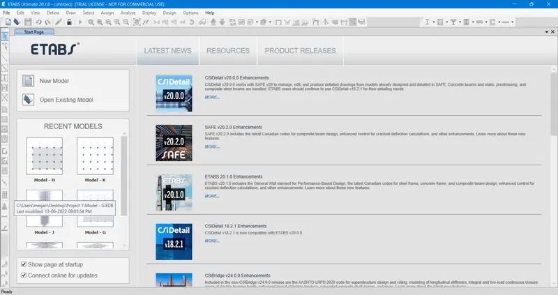
- After selecting and opening of the Model G, try to open the Analysed Result Table.
- For that from the Model Explorer Window select Table < Analysis Results < Model Information < Table - Model Periods and Frequencies.
- Then Right click over the Table - Model Periods and Frequencies and select Show Table.
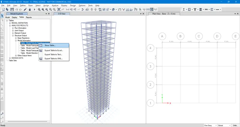
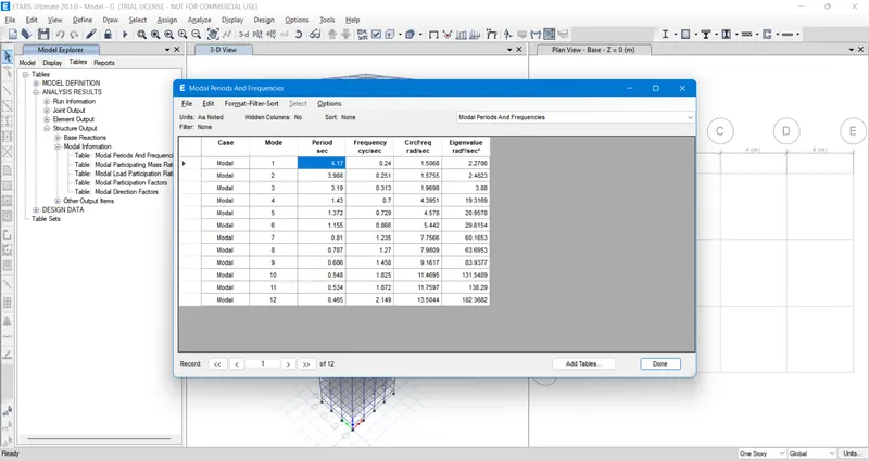
- A New Tab will be opened after selecting Show table named Model Periods and Frequencies.
- Here we can see the Modal 1's Periodic second = 4.17 and we can note it down in the Result Table as required.
- Now close the opened Model - G file by selecting File < Close to open next file from the Home.
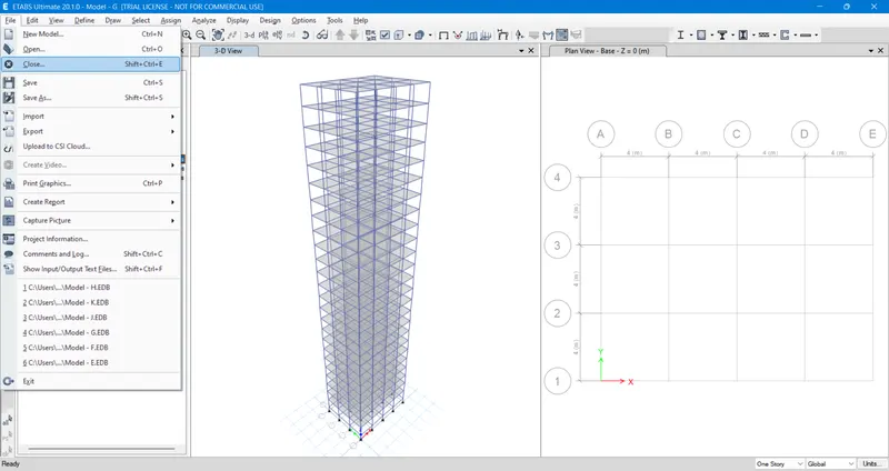
1 d) BUILDING H : (10 STOREY WITH VARYING COLUMN SIZES)
- After closing the Model - G by File < Close, Now click and select the created Model H file displaying in the Recent Models.
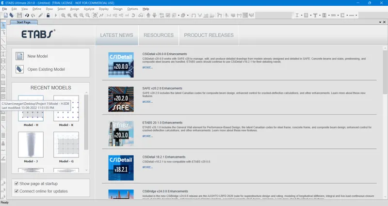
- After selecting and opening of the Model H, try to open the Analysed Result Table.
- For that from the Model Explorer Window select Table < Analysis Results < Model Information < Table - Model Periods and Frequencies.
- Then Right click over the Table - Model Periods and Frequencies and select Show Table.
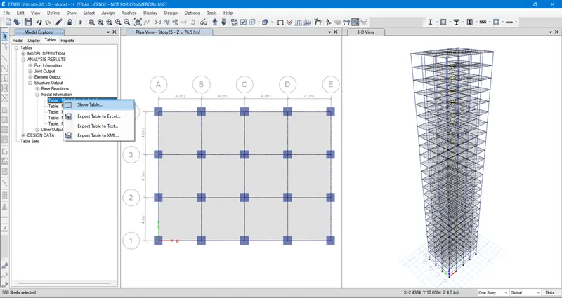
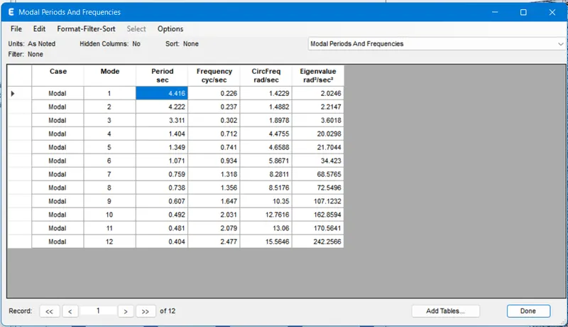
- A New Tab will be opened after selecting Show table named Model Periods and Frequencies.
- Here we can see the Modal 1's Periodic second = 4.416 and we can note it down in the Result Table as required.
- Now close the opened Model - H file by selecting File < Close to open next file from the Home.
2. ) EFFECT OF MASS ON TIME PERIOD :
2 a) BUILDING H : (25 STOREY WITH 3 KN/SQ.M IMPOSED LOAD)
- Open a Etabs software then click and select already created Model H file displaying in the Recent Models.
- After selecting and opening of the Model H, try to open the Analysed Result Table.
- For that from the Model Explorer Window select Table < Analysis Results < Model Information < Table - Model Periods and Frequencies.
- Then Right click over the Table - Model Periods and Frequencies and select Show Table.
- A New Tab will be opened after selecting Show table named Model Periods and Frequencies.
- Here we can see the Modal 1's Periodic second = 4.416 and we can note it down in the Result Table as required.
- Now close the opened Model - H file by selecting File < Close to open next file from the Home.
2 b) BUILDING J : (25 STOREY WITH 3.3 KN/SQ.M IMPOSED LOAD)
- After closing the Model - H by File < Close, Now click and select the created Model J file displaying in the Recent Models.
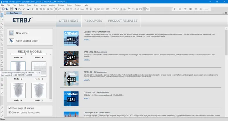
- After selecting and opening of the Model J, try to open the Analysed Result Table.
- For that from the Model Explorer Window select Table < Analysis Results < Model Information < Table - Model Periods and Frequencies.
- Then Right click over the Table - Model Periods and Frequencies and select Show Table.
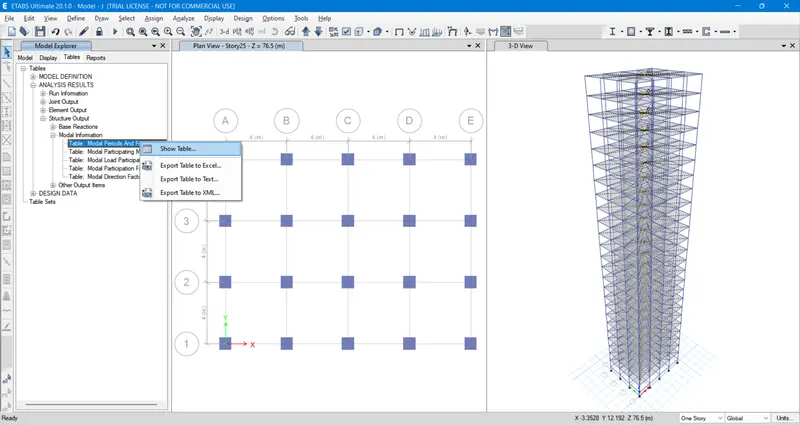
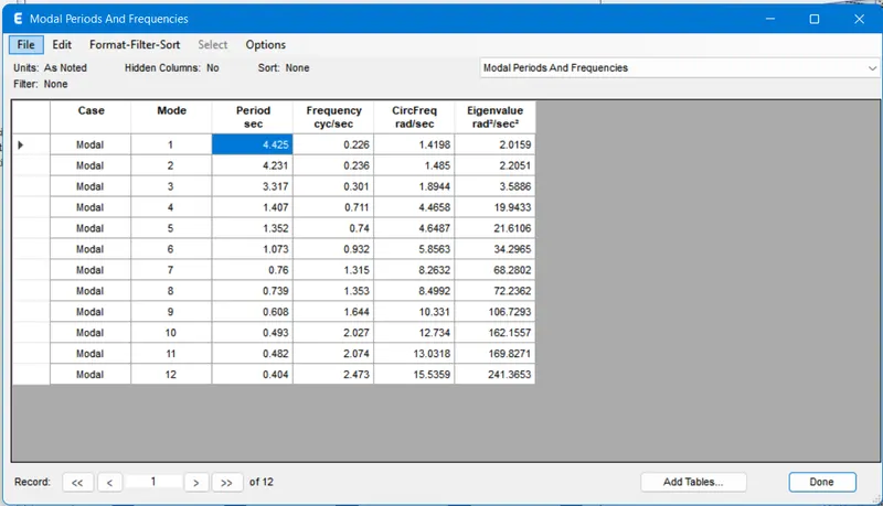
- A New Tab will be opened after selecting Show table named Model Periods and Frequencies.
- Here we can see the Modal 1's Periodic second = 4.425 and we can note it down in the Result Table as required.
- Now close the opened Model - J file by selecting File < Close to open next file from the Home.
2 c) BUILDING K : (25 STOREY WITH 3.6 KN/SQ.M IMPOSED LOAD)
- After closing the Model - J by File < Close, Now click and select the created Model K file displaying in the Recent Models.
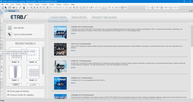
- After selecting and opening of the Model K, try to open the Analysed Result Table.
- For that from the Model Explorer Window select Table < Analysis Results < Model Information < Table - Model Periods and Frequencies.
- Then Right click over the Table - Model Periods and Frequencies and select Show Table.
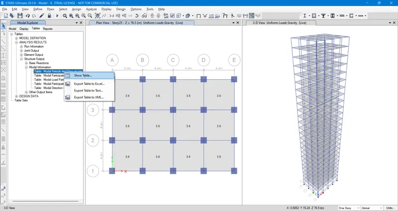
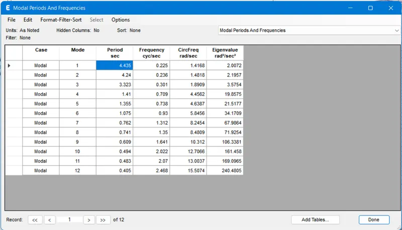
- A New Tab will be opened after selecting Show table named Model Periods and Frequencies.
- Here we can see the Modal 1's Periodic second = 4.435 and we can note it down in the Result Table as required.
- Now close the opened Model - K file by selecting File < Close to open next file from the Home.
3. ) EFFECT OF BUILDING HEIGHT ON TIME PERIOD :
3 a) BUILDING A : (2 STOREY)
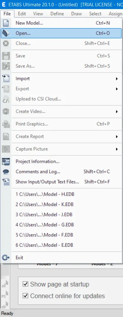
- Open a Etabs software then click and open the Model - A, which was already saved.
- To open it select File < Open < Open Model File Tab < Model - A.
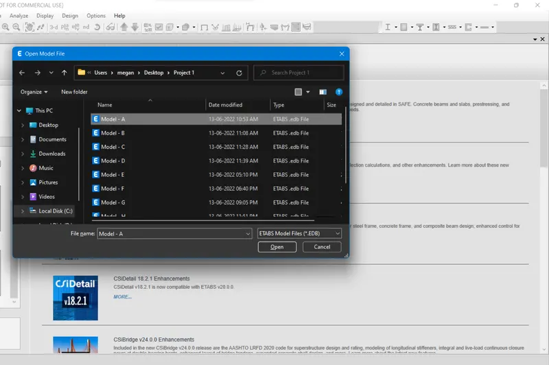
- After selecting and opening of the Model A, try to open the Analysed Result Table.
- For that from the Model Explorer Window select Table < Analysis Results < Model Information < Table - Model Periods and Frequencies.
- Then Right click over the Table - Model Periods and Frequencies and select Show Table.
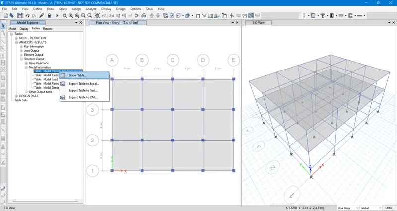
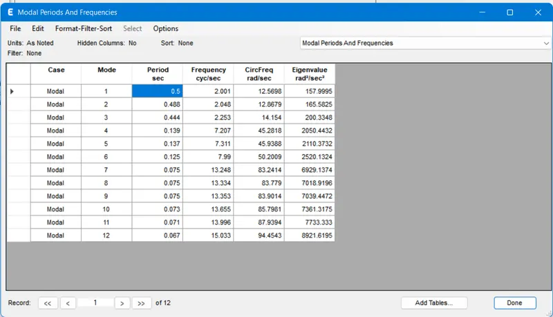
- A New Tab will be opened after selecting Show table named Model Periods and Frequencies.
- Here we can see the Modal 1's Periodic second = 0.5 and we can note it down in the Result Table as required.
- Now close the opened Model - A file by selecting File < Close to open next file from the Home.
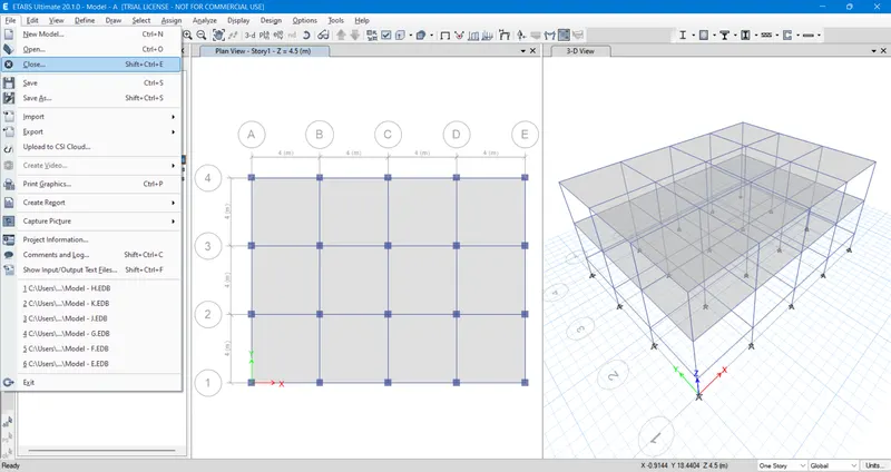
3 b) BUILDING B : (2 STOREY)
- After closing the Model - A by File < Close, Now try to open the Model - B, which was already saved.
- To open it select File < Open < Open Model File Tab < Model - B.
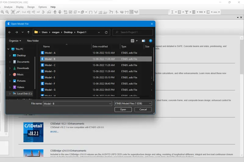
- After selecting and opening of the Model B, try to open the Analysed Result Table.
- For that from the Model Explorer Window select Table < Analysis Results < Model Information < Table - Model Periods and Frequencies.
- Then Right click over the Table - Model Periods and Frequencies and select Show Table.
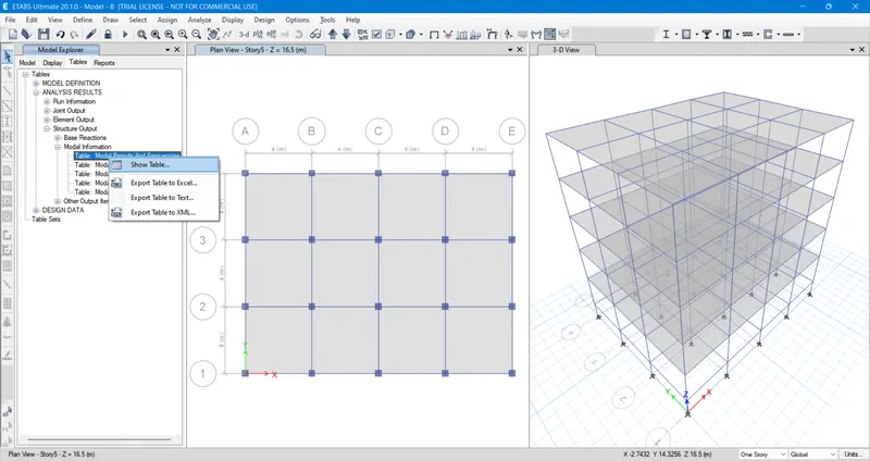
- A New Tab will be opened after selecting Show table named Model Periods and Frequencies.
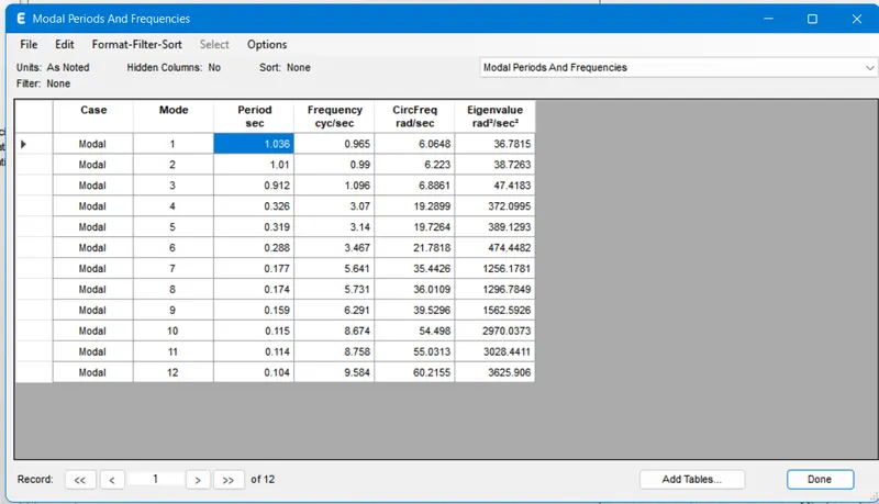
- Here we can see the Modal 1's Periodic second = 1.036 and we can note it down in the Result Table as required.
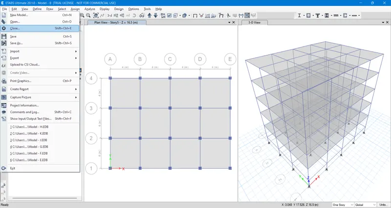
- Now close the opened Model - B file by selecting File < Close to open next file from the Home.
3 c) BUILDING F : (2 STOREY)
- After closing the Model - B by File < Close, Now try to open the Model - F, which was already saved.
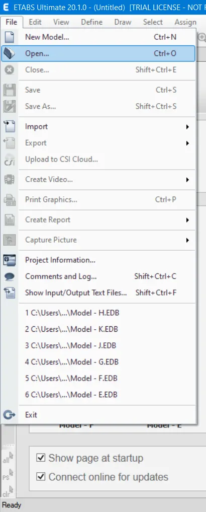
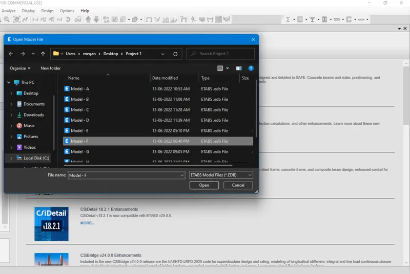
- To open it select File < Open < Open Model File Tab < Model - F.
- After selecting and opening of the Model F, try to open the Analysed Result Table.
- For that from the Model Explorer Window select Table < Analysis Results < Model Information < Table - Model Periods and Frequencies.
- Then Right click over the Table - Model Periods and Frequencies and select Show Table.
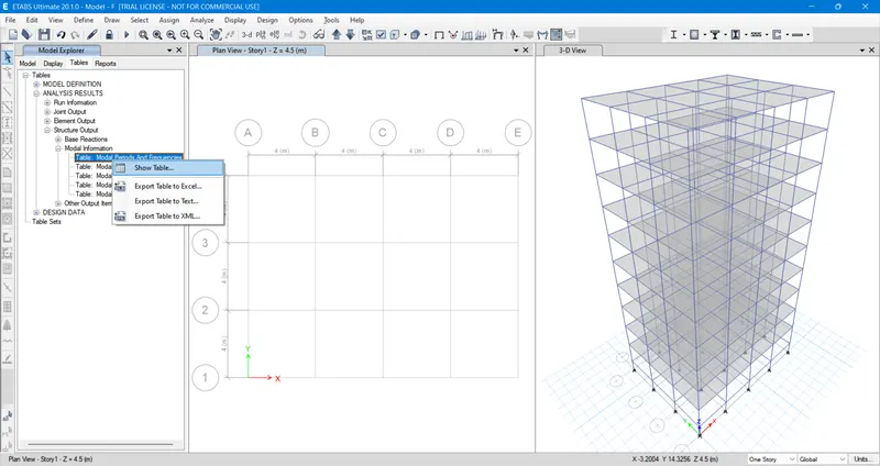
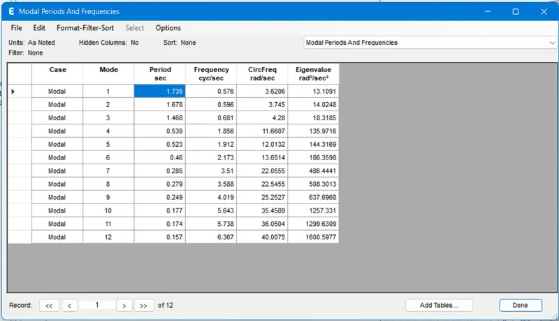
- A New Tab will be opened after selecting Show table named Model Periods and Frequencies.
- Here we can see the Modal 1's Periodic second = 1.735 and we can note it down in the Result Table as required.
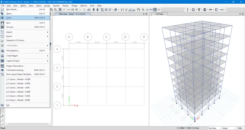
- Now close the opened Model - F file by selecting File < Close to open next file from the Home.
3 d) BUILDING H : (2 STOREY)
- After closing the Model - F by File < Close, Now try to open the Model - H, which was already saved.
- To open it select File < Open < Open Model File Tab < Model - H.
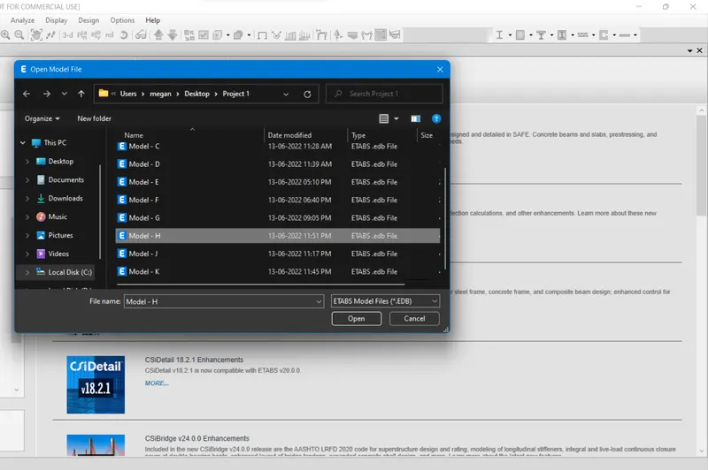
- After selecting and opening of the Model H, try to open the Analysed Result Table.
- For that from the Model Explorer Window select Table < Analysis Results < Model Information < Table - Model Periods and Frequencies.
- Then Right click over the Table - Model Periods and Frequencies and select Show Table.
- A New Tab will be opened after selecting Show table named Model Periods and Frequencies.
- Here we can see the Modal 1's Periodic second = 4.416 and we can note it down in the Result Table as required.
- Now close the opened Model - H file by selecting File < Close to open next file from the Home.
4. ) EFFECT OF COLUMN ORIENTATION ON TIME PERIOD :
4 a) BUILDING B : (ALL FLOORS COLUMN SIZE 400X400)
- After closing the Model - H by File < Close, Now try to open the Model - B, which was already saved.
- To open it select File < Open < Open Model File Tab < Model - B.
- After selecting and opening of the Model B, try to open the Analysed Result Table.
- For that from the Model Explorer Window select Table < Analysis Results < Model Information < Table - Model Periods and Frequencies.
- Then Right click over the Table - Model Periods and Frequencies and select Show Table.
- A New Tab will be opened after selecting Show table named Model Periods and Frequencies.
- Here we can see the Modal 1's Periodic second = 1.036 and we can note it down in the Result Table as required.
- Now close the opened Model - B file by selecting File < Close to open next file from the Home.
4 b) BUILDING C : (ALL FLOORS COLUMN SIZE 550X300 ORIENTED IN X - DIRECTION)
- After closing the Model - B by File < Close, Now try to open the Model - C, which was already saved.
- To open it select File < Open < Open Model File Tab < Model - C.
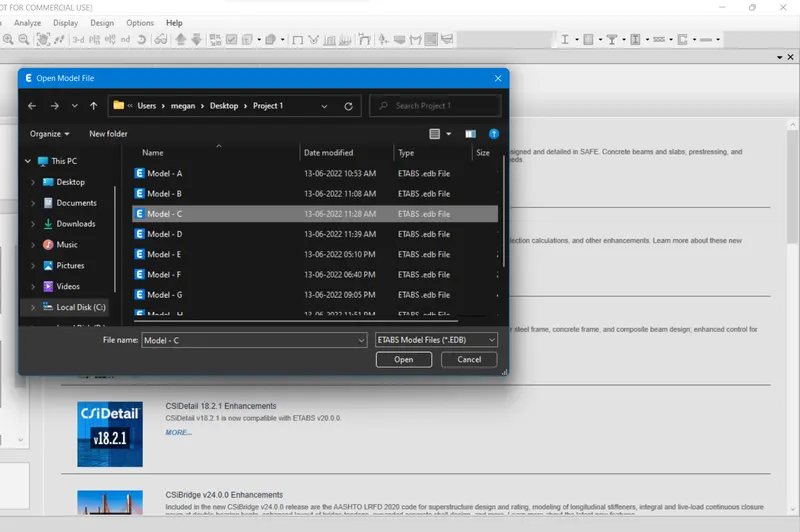
- After selecting and opening of the Model C, try to open the Analysed Result Table.
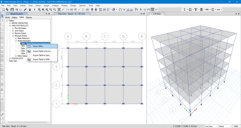
- For that from the Model Explorer Window select Table < Analysis Results < Model Information < Table - Model Periods and Frequencies.
- Then Right click over the Table - Model Periods and Frequencies and select Show Table.
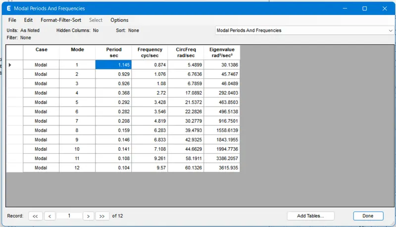
- A New Tab will be opened after selecting Show table named Model Periods and Frequencies.
- Here we can see the Modal 1's Periodic second = 1.145 and we can note it down in the Result Table as required.
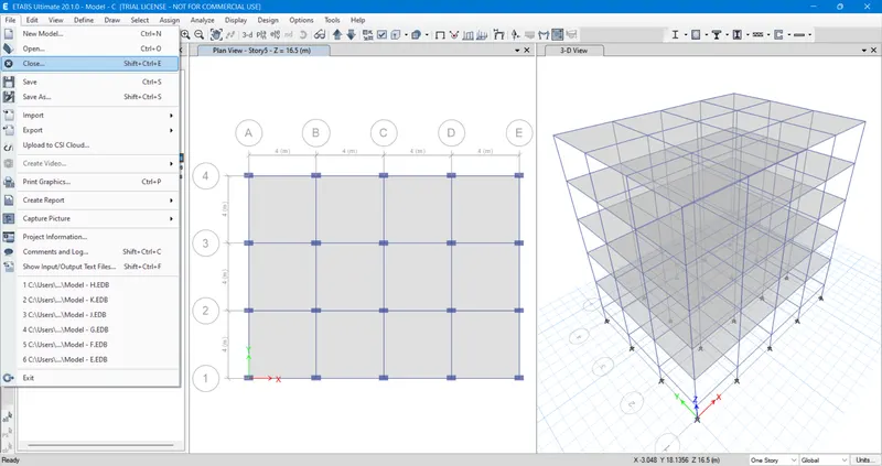
- Now close the opened Model - C file by selecting File < Close to open next file from the Home.
4 c) BUILDING D : (ALL FLOORS COLUMN SIZE 300X550 ORIENTED IN Y - DIRECTION)
- After closing the Model - C by File < Close, Now try to open the Model - D, which was already saved.
- To open it select File < Open < Open Model File Tab < Model - D.
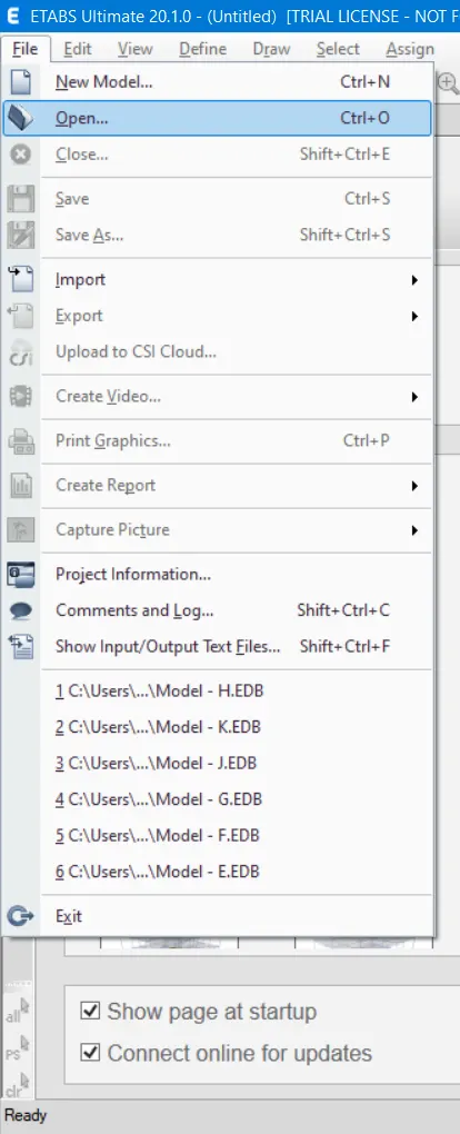
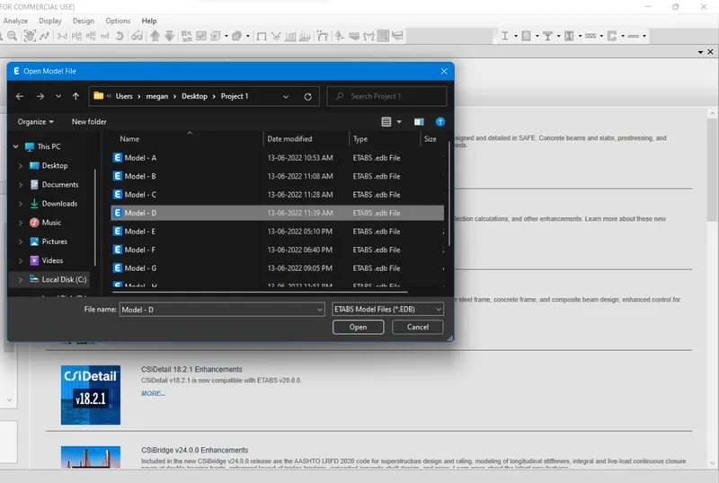
- After selecting and opening of the Model D, try to open the Analysed Result Table.
- For that from the Model Explorer Window select Table < Analysis Results < Model Information < Table - Model Periods and Frequencies.
- Then Right click over the Table - Model Periods and Frequencies and select Show Table.
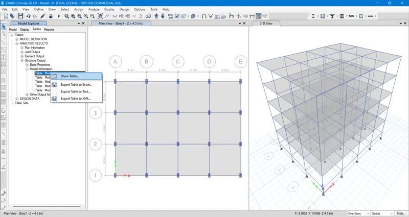
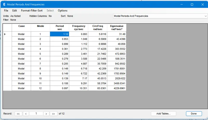
- A New Tab will be opened after selecting Show table named Model Periods and Frequencies.
- Here we can see the Modal 1's Periodic second = 1.12 and we can note it down in the Result Table as required.
- Now close the opened Model - D file by selecting File < Close to open next file from the Home.
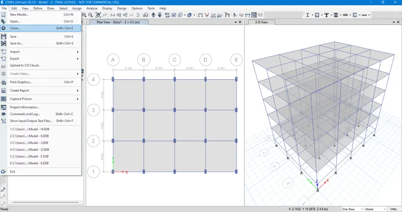
5. ) EFFECT OF FLEXURAL STIFFNESS OF STRUCTURAL ELEMENT ON MODE SHAPES
5 a ) BUILDING B : (FLEXURAL STIFFNESS OF BEAMS CLOSE TO NIL "ZERO INERTIA")
- After closing the Model - D by File < Close, Now try to open the Model - B, which was already saved.
- To open it select File < Open < Open Model File Tab < Model - B.
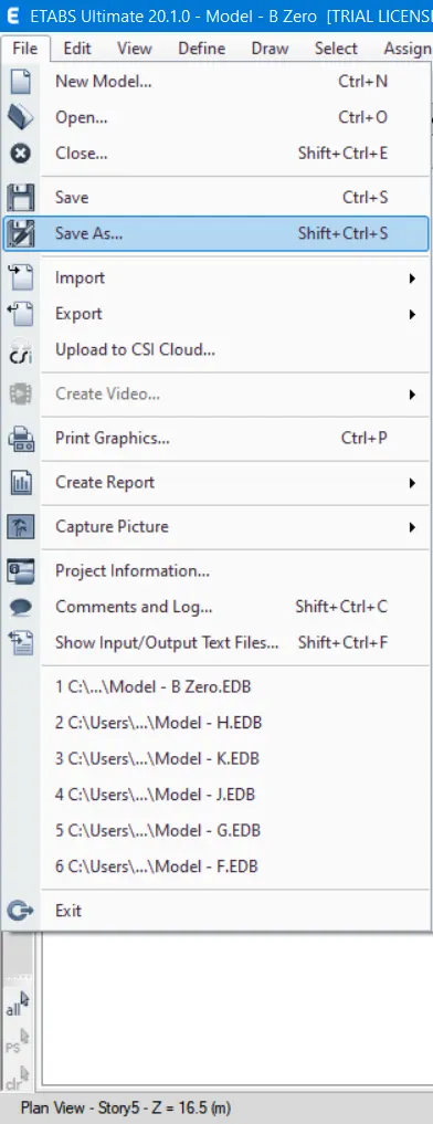
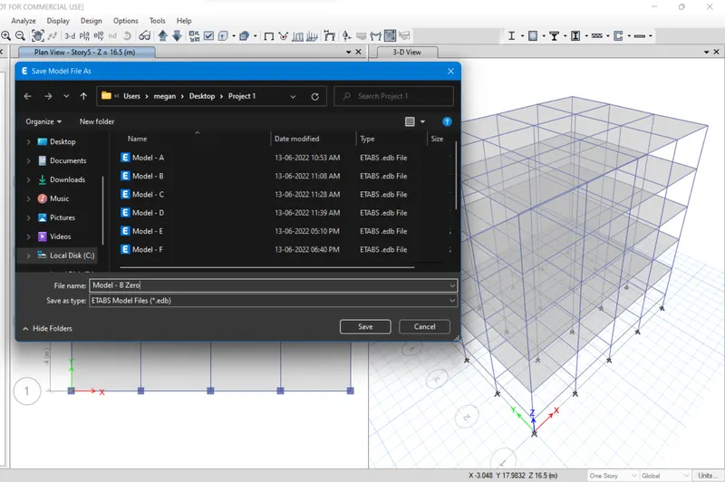
- After opening of the existing Model - B, Now the same file should be Save as in the name of Model - B Zero.
- The above was done by selecting File < Save As < Save Model File As and in File Name = Model - B Zero and click Save.
- Now to change the Flexural stiffness of beams close to nil, the Beam properties should be edited.
- For that select Define < Section Properties < Frame Section then the Frame Properties Tab will be opened.
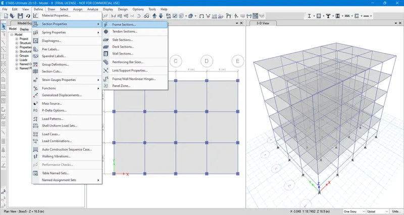
- From Frame Properties Tab select the Beam B300x400 and click Modify/show Property.
- Then the Frame Section Property Data Tab will be opened.
- In the opened Tab click Modify/show Modifiers to open Property/Stiffness Modification Factors Tab.
- Here, make the Moment of inertia about 2 axis = 0.1 and Moment of inertia about 3 axis = 0.1 and click OK.
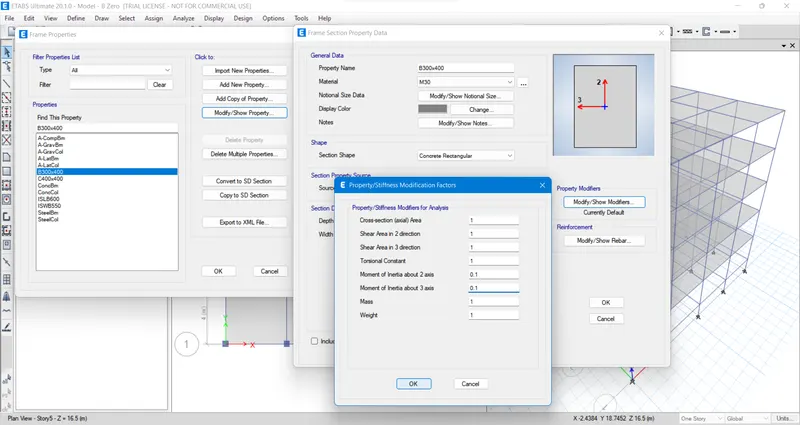
- After making the Moment of inertia about 2 and 3 axis = 0.1 , we can Run Analysis from the option given in the tool bar.
- After the completion of the analysis, the Deformed shape of the Building will be visible in 3D view Window.
- We can see the Analysis Result from the Table option below the Model Explorer Window at the left side of the workspace.
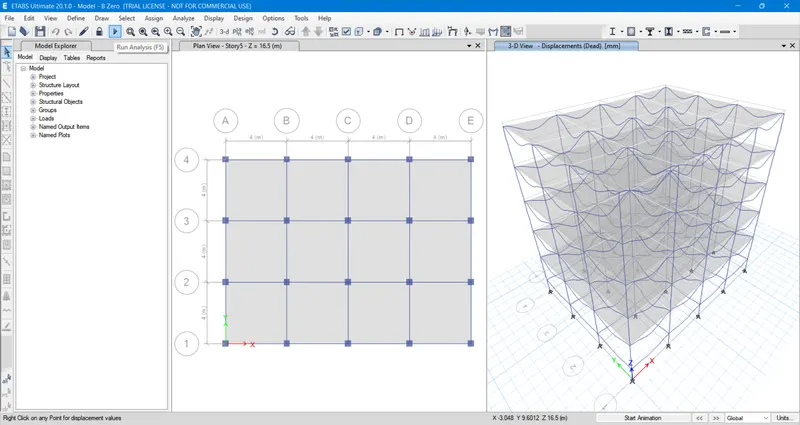
- After the Analysing the 'Model B Zero', try to open the Analysed Result Table.
- For that from the Model Explorer Window select Table < Analysis Results < Model Information < Table - Model Periods and Frequencies.
- Then Right click over the Table - Model Periods and Frequencies and select Show Table.
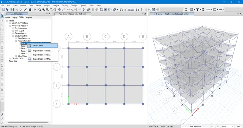
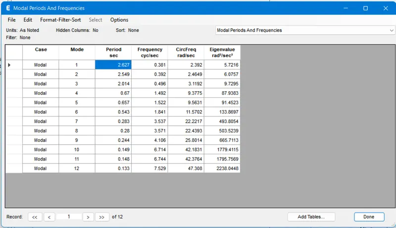
- A New Tab will be opened after selecting Show table named Model Periods and Frequencies.
- Here we can see the Modal 1's Periodic second = 2.627 and we can note it down in the Result Table as required.
- Now save the Analysed Model - B Zero by selecting File < Save.
- Finally close the Saved file by selecting File < Close to open next file from the Home.
5 b ) BUILDING B : (FULL FLEXURAL STIFFNESS OF BEAMS "REGULAR")
- After closing the Model - B Zero by File < Close, Now again try to open the Model - B to see the Full flexural stiffness of beams.
- To open it select File < Open < Open Model File Tab < Model - B.
- After selecting and opening of the Model B, try to open the Analysed Result Table.
- For that from the Model Explorer Window select Table < Analysis Results < Model Information < Table - Model Periods and Frequencies.
- Then Right click over the Table - Model Periods and Frequencies and select Show Table.
- A New Tab will be opened after selecting Show table named Model Periods and Frequencies.
- Here we can see the Modal 1's Periodic second = 1.036 and we can note it down in the Result Table as required.
- Now close the opened Model - B file by selecting File < Close to open next file from the Home.
6. ) EFFECT OF AXIAL STIFFNESS OF VERTICAL MEMBERS ON MODE SHAPES :
6 a ) BUILDING H (AXIAL CROSS SECTION FOR COLUMNS IS CLOSE TO NIL "ZERO AXIAL AREA")
- After closing the Model - B by File < Close, Now try to open the Model - H to apply Zero axial area to all columns.
- To open it select File < Open < Open Model File Tab < Model - H.
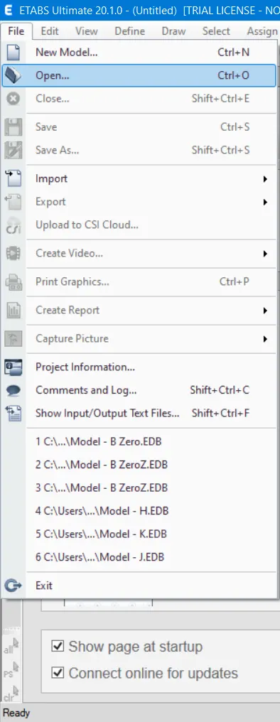
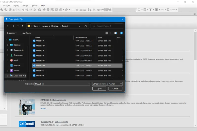
- After opening of the existing Model - H, Now the same file should be Save as in the name of Model - H (Zero).
- The above was done by selecting File < Save As < Save Model File As and in File Name = Model - H (Zero) and click Save.
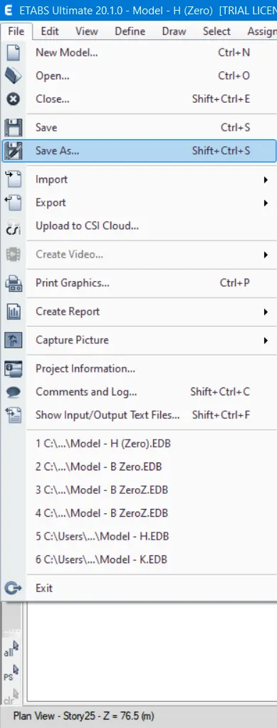
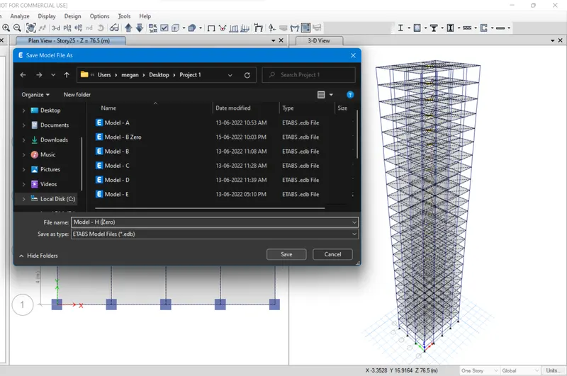
- Now to change the Axial cross section for columns close to nil, the Columns properties should be edited.
- For that select Define < Section Properties < Frame Section then the Frame Properties Tab will be opened.
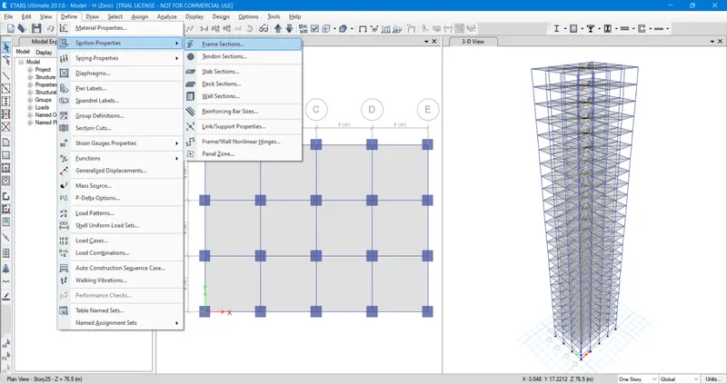
- From Frame Properties Tab select the Column C800x800 and click Modify/show Property.
- Then the Frame Section Property Data Tab will be opened.
- In the opened Tab click Modify/show Modifiers to open Property/Stiffness Modification Factors Tab.
- Here, make the Cross section (axial) area = 0.1 and click OK.
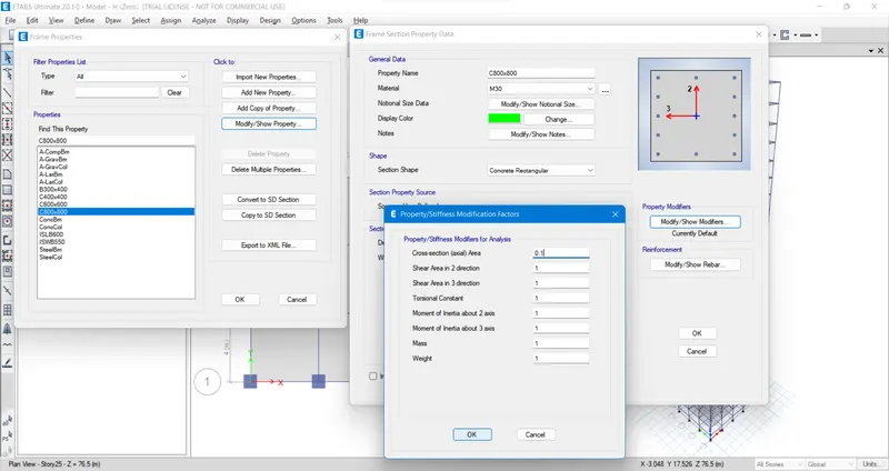
- After making the Cross section (axial) area = 0.1 , we can Run Analysis from the option given in the tool bar.
- After the completion of the analysis, the Deformed shape of the Building will be visible in 3D view Window.
- We can see the Analysis Result from the Table option below the Model Explorer Window at the left side of the workspace.
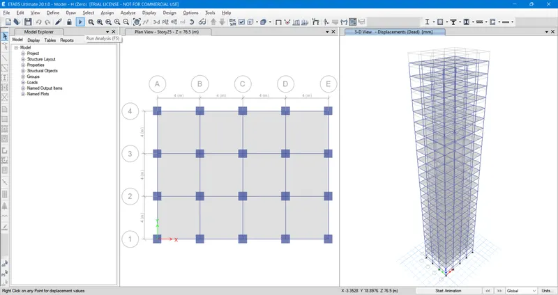
- After the Analysing the 'Model H (Zero)', try to open the Analysed Result Table.
- For that from the Model Explorer Window select Table < Analysis Results < Model Information < Table - Model Periods and Frequencies.
- Then Right click over the Table - Model Periods and Frequencies and select Show Table.
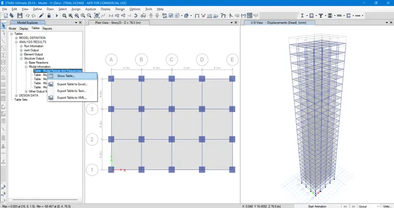
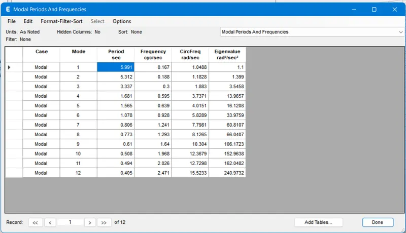
- A New Tab will be opened after selecting Show table named Model Periods and Frequencies.
- Here we can see the Modal 1's Periodic second = 5.991 and we can note it down in the Result Table as required
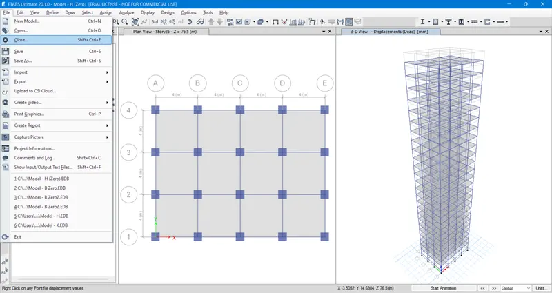
- Now save the Analysed Model - H (Zero) by selecting File < Save.
- Finally close the Saved file by selecting File < Close to open next file from the Home.
6 b ) BUILDING H (FULL AXIAL CROSS SECTION FOR COLUMNS "REGULAR")
- After closing the Model - H (Zero) by File < Close, Now try to open the Model - H to see its Full axial cross section for columns.
- To open it select File < Open < Open Model File Tab < Model - H.
- After selecting and opening of the Model H, try to open the Analysed Result Table.
- For that from the Model Explorer Window select Table < Analysis Results < Model Information < Table - Model Periods and Frequencies.
- Then Right click over the Table - Model Periods and Frequencies and select Show Table.
- A New Tab will be opened after selecting Show table named Model Periods and Frequencies.
- Here we can see the Modal 1's Periodic second = 4.416 and we can note it down in the Result Table as required.
- Now close the opened Model - H file by selecting File < Close to open next file from the Home.
7. ) EFFECT OF DEGREE OF FIXITY AT COLUMN BASED ON MODE SHAPES :
7 a ) BUILDING B (COLUMN SUPPORT PINNED "REGULAR")
- After closing the Model - H by File < Close, Now try to open the Model - B with the column support as Pinned.
- To open it select File < Open < Open Model File Tab < Model - B.
- After selecting and opening of the Model B, try to open the Analysed Result Table.
- For that from the Model Explorer Window select Table < Analysis Results < Model Information < Table - Model Periods and Frequencies.
- Then Right click over the Table - Model Periods and Frequencies and select Show Table.
- A New Tab will be opened after selecting Show table named Model Periods and Frequencies.
- Here we can see the Modal 1's Periodic second = 1.036 and we can note it down in the Result Table as required.
- Now close the opened Model - B file by selecting File < Close to open next file from the Home.
7 b ) BUILDING B (COLUMN SUPPORT "FIXED")
- After closing the Model - B by File < Close, Now try to open the same Model - B with the column support as Pinned.
- To open it select File < Open < Open Model File Tab < Model - B.
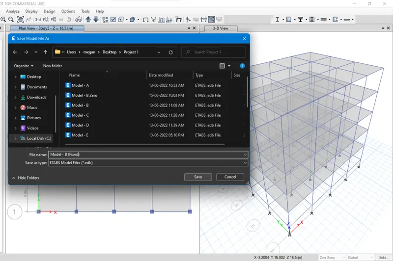
- After opening of the existing Model - B, Now the same file should be Save as in the name of Model - B (Fixed).
- The above was done by selecting File < Save As < Save Model File As and in File Name = Model - B (Fixed) and click Save.
- Now, click the Plan icon present at the Tool Bar above the workspace.
- Then the Select plan View Tab will be opened, there select 'Base' and click Apply.
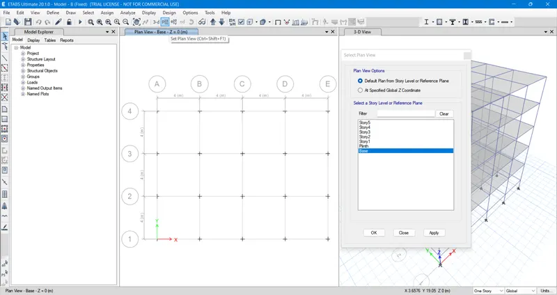
- Here in Base Plan View select all the column supports by windows selection.
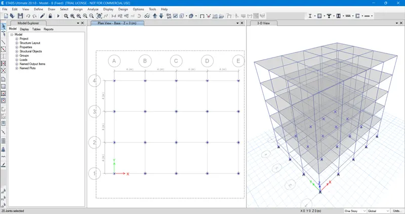
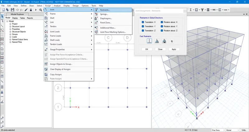
- After the selection of all the supports of the Columns, change the Pinned Supports as Fixed Supports.
- It will be done by selecting Assign < Joint < Restraints .
- Then click Restraints and the Joint Assignment - Restraints Tab will be opened.
- From the opened Tab click and select the Fixed support as First icon below Last Restraints and click OK to assign.
- After changing the Pinned Support as Fixed Support , we can Run Analysis from the option given in the tool bar.
- After the completion of the analysis, the Deformed shape of the Building will be visible in 3D view Window.
- We can see the Analysis Result from the Table option below the Model Explorer Window at the left side of the workspace.
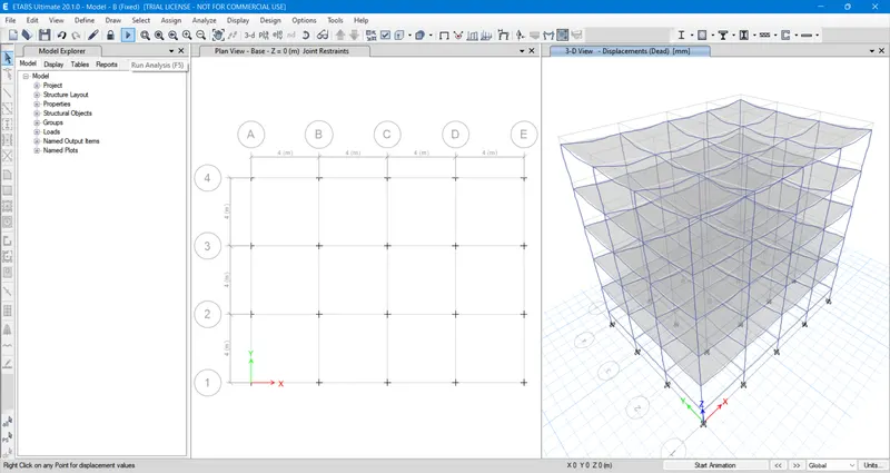
- After the Analysing the 'Model B (Fixed)', try to open the Analysed Result Table.
- For that from the Model Explorer Window select Table < Analysis Results < Model Information < Table - Model Periods and Frequencies.
- Then Right click over the Table - Model Periods and Frequencies and select Show Table.
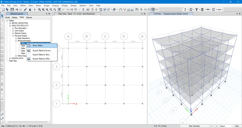
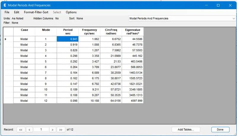
- A New Tab will be opened after selecting Show table named Model Periods and Frequencies.
- Here we can see the Modal 1's Periodic second = 0.941 and we can note it down in the Result Table as required.
- Now save the Analysed Model - B (Fixed) by selecting File < Save.
- Finally close the Saved file by selecting File < Close.