Project 1_Comparative study of different storey buildings for Seismic forces
AIM: To create 10 different models in the ETABS software and assess them on the following points:
-
Factors influencing the dynamic characteristics of a building
-
Factors influencing the Natural Period of a building
-
Factors influencing the Mode shape of oscillations
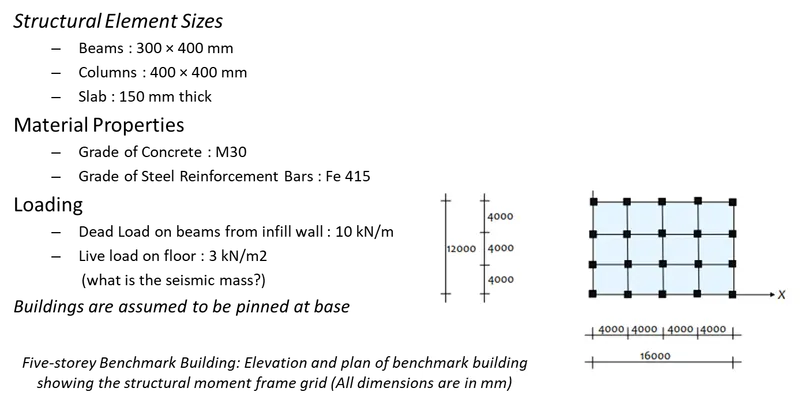
SPECIFICATIONS GIVEN IN THE QUESTION:
MODELS TO BE CREATED:
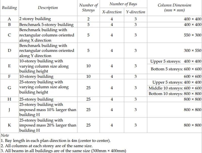
QUESTIONS TO BE ANSWERED:
- Effect of stiffness on T: Compare fundamental natural periods of buildings E & F as well as G & H. Why is there a marginal or significant difference in the fundamental natural periods?
- Effect of mass on T: Compare fundamental natural periods of buildings H, J and K. Have the buildings become more flexible or stiff due to change in mass?
- Effect of Building Height on T: How do the fundamental natural periods of Buildings A, B, F, and H change with a change in building height?
- Effect of Column Orientation on T: How do the fundamental natural periods of Buildings B, C, and D change with a change in column orientation?
- Effect of Flexural Stiffness of Structural Elements on mode shapes: Compare the fundamental mode shape of Building B in two situations when the flexural stiffness of beams relative to that of adjoining columns is very small versus when it is large.
- Effect of Axial Stiffness of Vertical Members on mode shapes: Compare the fundamental mode shape of Building H in two situations when the axial cross-sectional area of columns is very small versus when it is large.
- Effect of Degree of Fixity at column bases on mode shape: Compare the fundamental mode shape of Building B in two situations when the base of columns is pinned versus when it is fixed.
PROCEDURE:
First of all, we will create all the 10 models. Please have a look at the below procedure and snips for the walkthrough of how we create 10 different types of models.
- Model A:
- Open the etabs software.
- Create a new file.
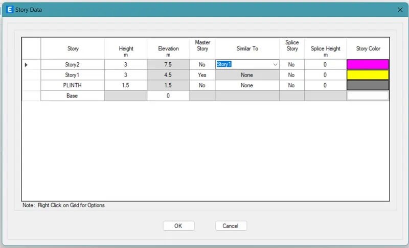
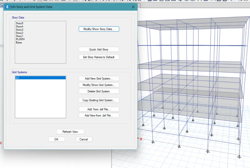
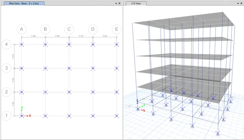
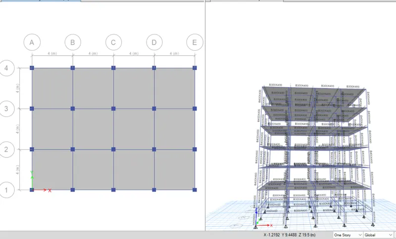
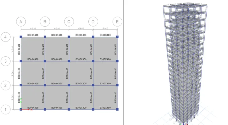
- Now add two storeys with a base and plinth level.
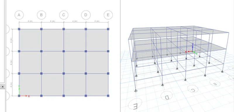
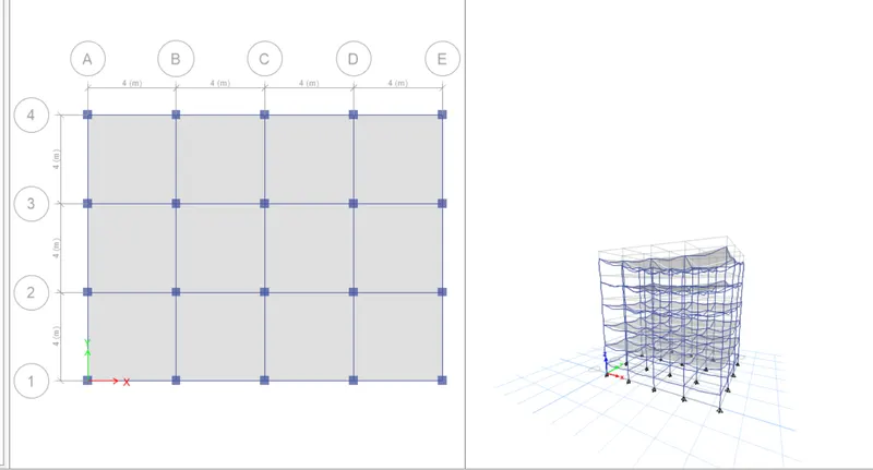
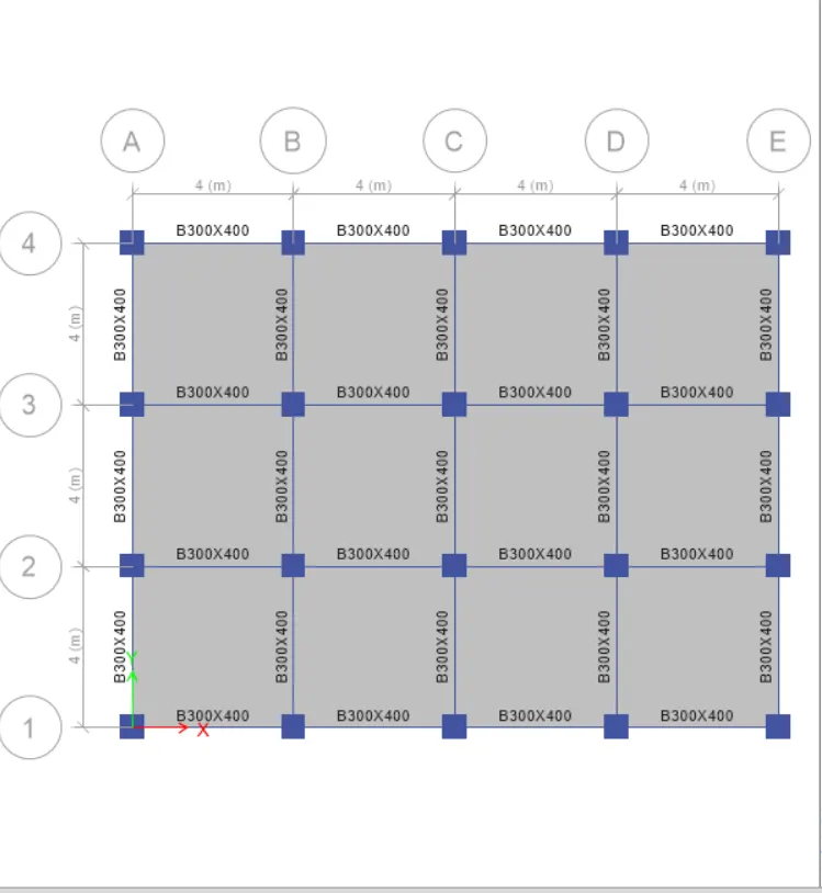
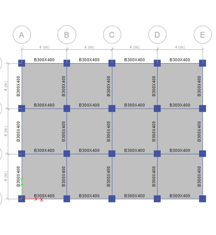
- Define the grids and metric systems.
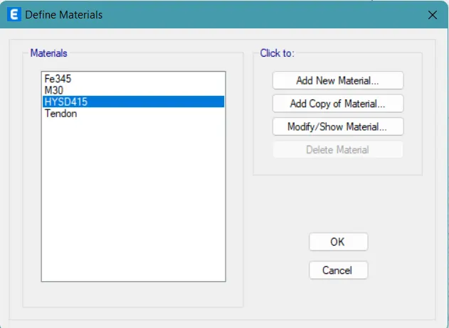
- Then define the materials.
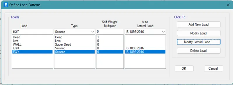
- Now assign the load patterns and combinations.
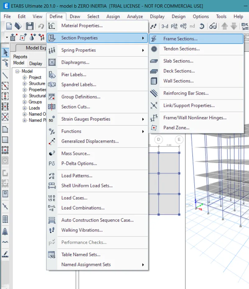
- Then create the beam, column, and slab section using the define tab.
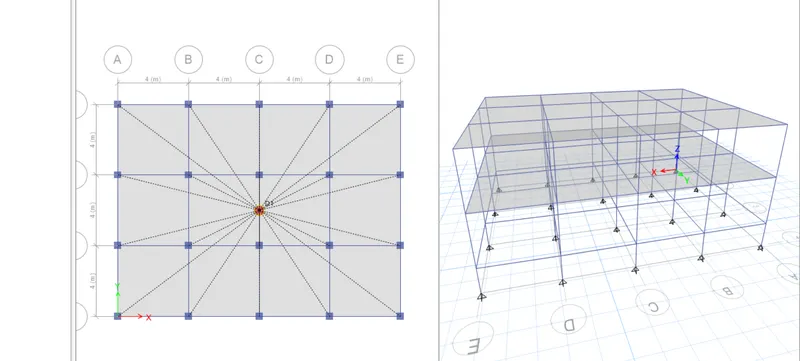
- Finally using the quick shortcuts add the components.
- Once the components are added, assign the wall load of 10KN/m² and the live load on the slab of 3 KN/m².
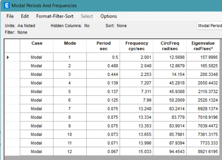
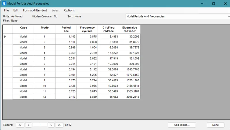
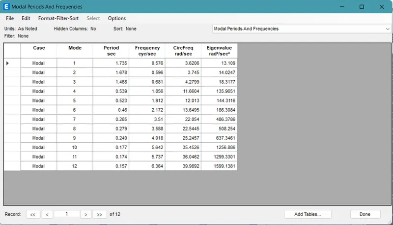
- Analyze the model and check the modal analysis time periods.
- Model B:
- Now create a copy of the Model A file.
- Change the number of stories in the new model.
- Analyze the model.
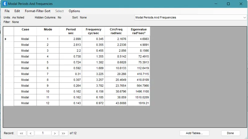
- Check the modal time period for it.
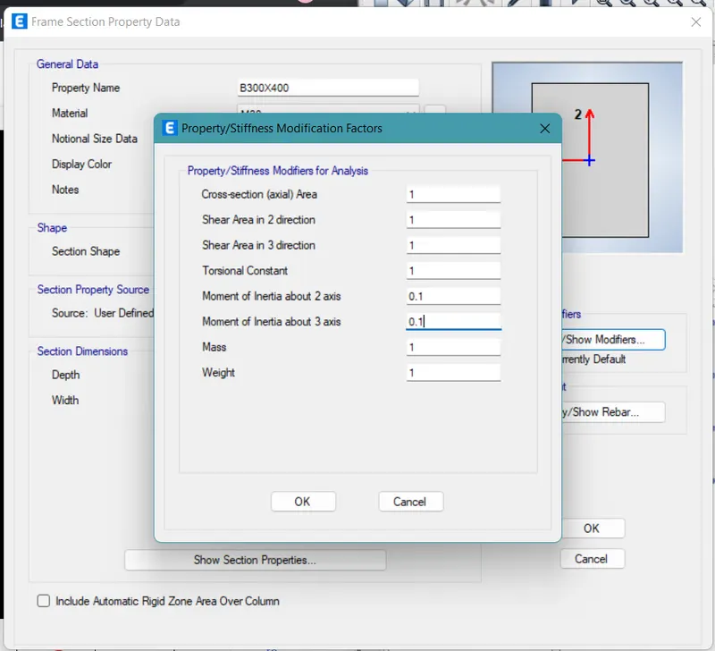
- Now again create a copy of the same file and then in the modification property of the beam, modify the flexural stiffness to as low as 0.1.
- Now again analyze the model and save the table of modal analysis values.
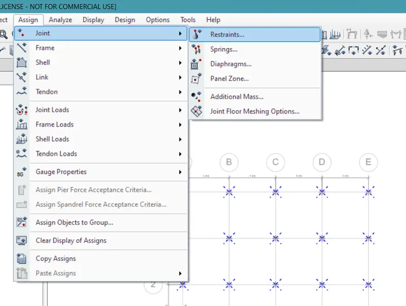
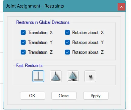
- Now again create a copy of the Model B file and modify the property of the joints to fixed ones.
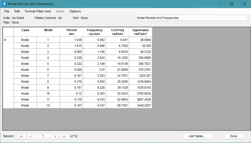
- Again analyze the model and note down the modal analysis values for it.
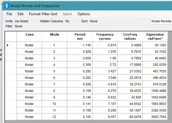
- Model C:
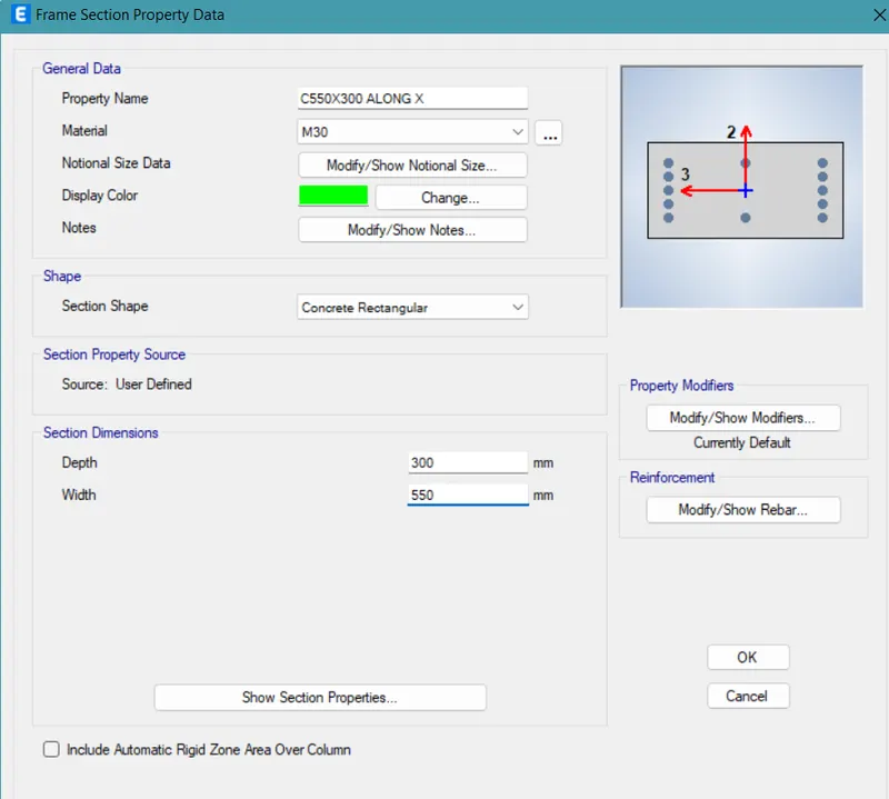
- Now create a copy of the Model B file and then change the properties of the column.
- Change the dimensions to 550 x 300mm.
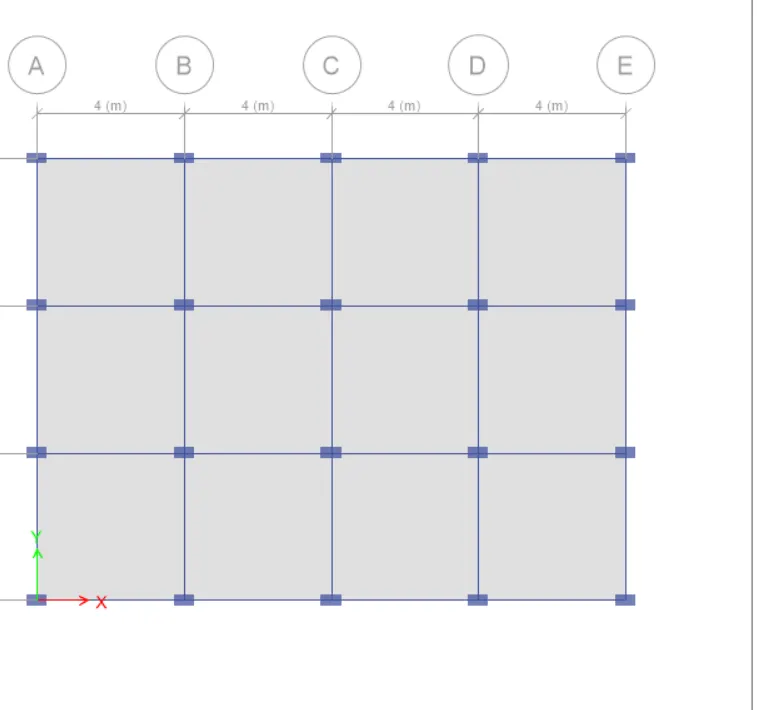
- The columns should be aligned along the X-axis.
- Again analyze the model and note down the modal analysis values for it.
- Model D:
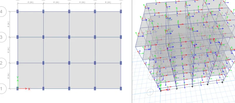
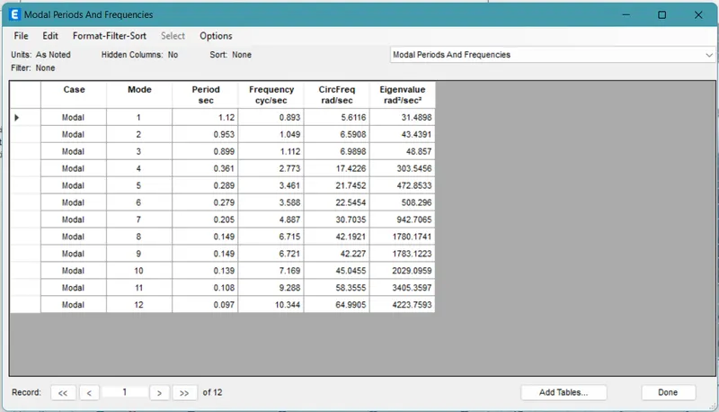
- Now create a copy of the Model C.
- Align the columns back in the Y-axis direction.
- Again analyze the model and note down the modal analysis values for it.
- Model E:
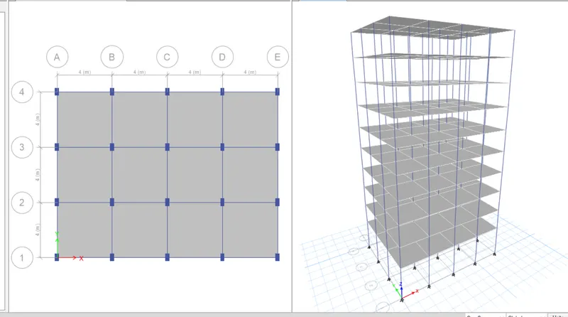
- Now create a copy of the Model D file.
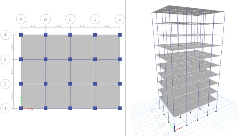
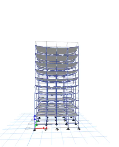
- Edit the number of stories from 5 to 10.
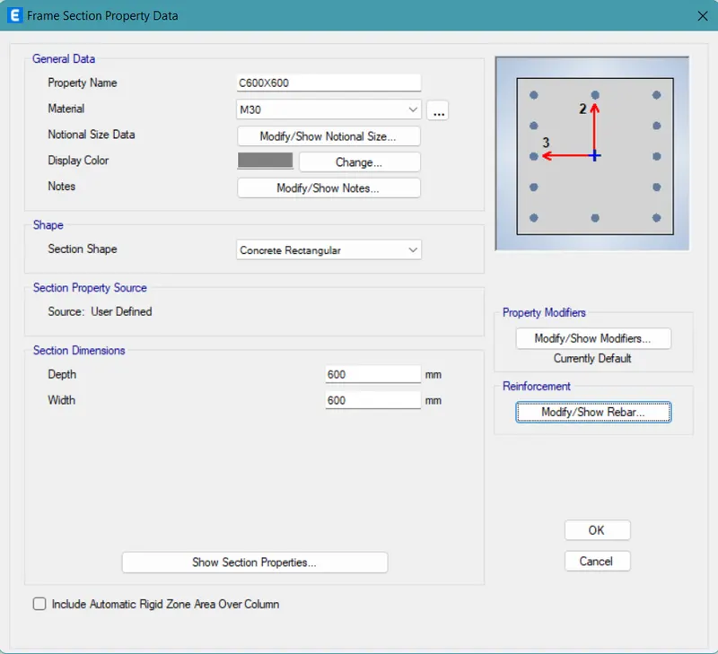
- Now change the column sizes of the whole building to C400x400 type.
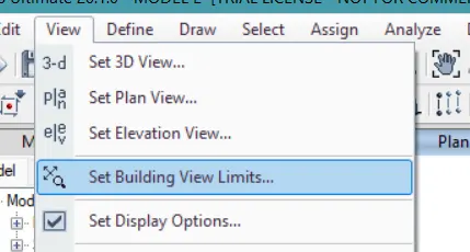
- Then go to the view tab.
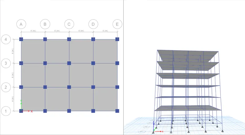
- Change the view settings up to storey 6.
- Then again change the column size to C600x600 type.
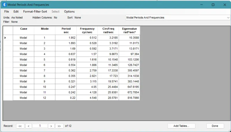
- Again analyze the model and note down the modal analysis values for it.
- Model F:
- Now create a copy of the Model E.
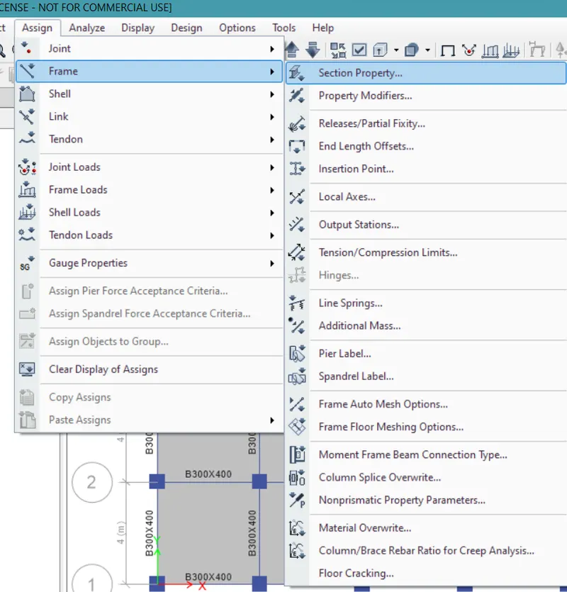
- Now change the whole building column type to C600x600.
- Again analyze the model and note down the modal analysis values for it.
- Model G:
- Now create a copy of the Model F file.
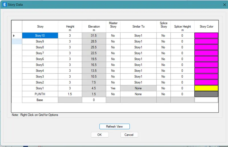
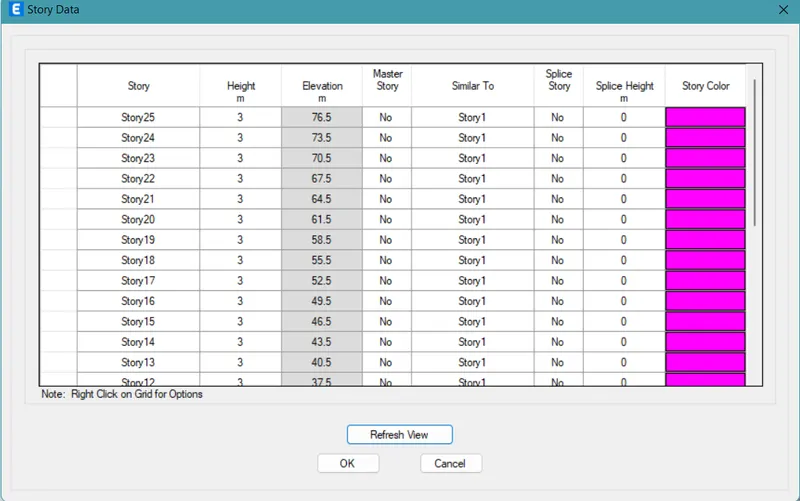
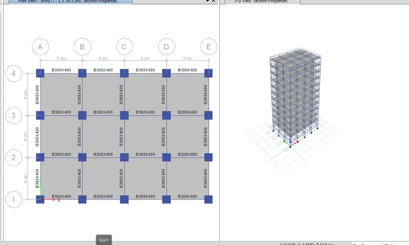
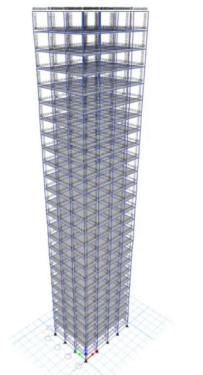
- Edit the number of storeys to 25 from 10.
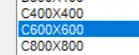
- Now firstly change the whole building's column sizes to C400x400 type.
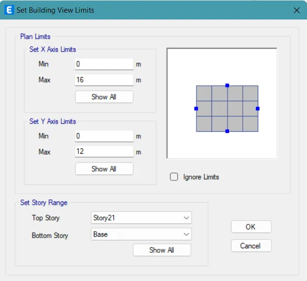
- Then from the view bar, change the build view up to 21 storey.
- Again Change the column type to C600x600.
- Then again from the view bar change the view settings to 11th storey.
- Change the column type to C800x800.
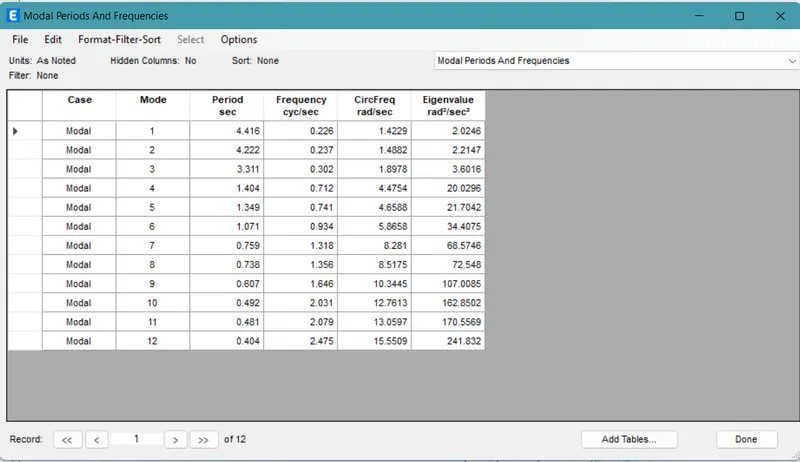
- Again analyze the model and note down the modal analysis values for it.
- Model H:
- Now create a copy of the Model G file.
- Change the column size of the whole building to C800x800.
- Again analyze the model and note down the modal analysis values for it.
- Now again create a copy of the Model H file.
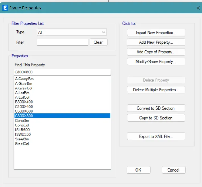
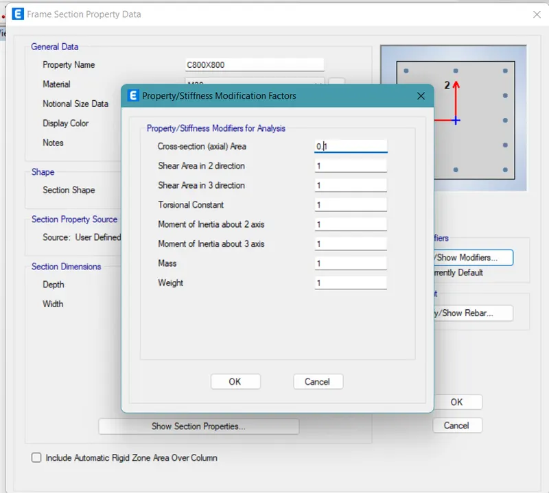
- From the define tab, change the properties of the column.
- Change the axial points to as low as 0.1.
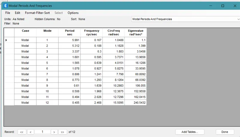
- Again analyze the model and note down the modal analysis values for it.
- Model J:
- Now create a copy of the Model H file.
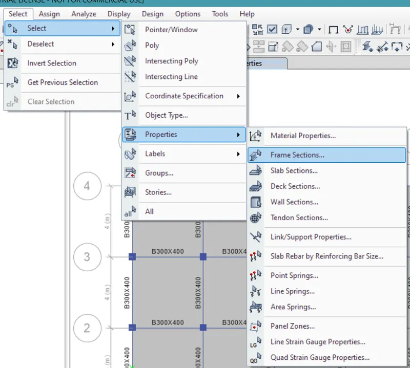
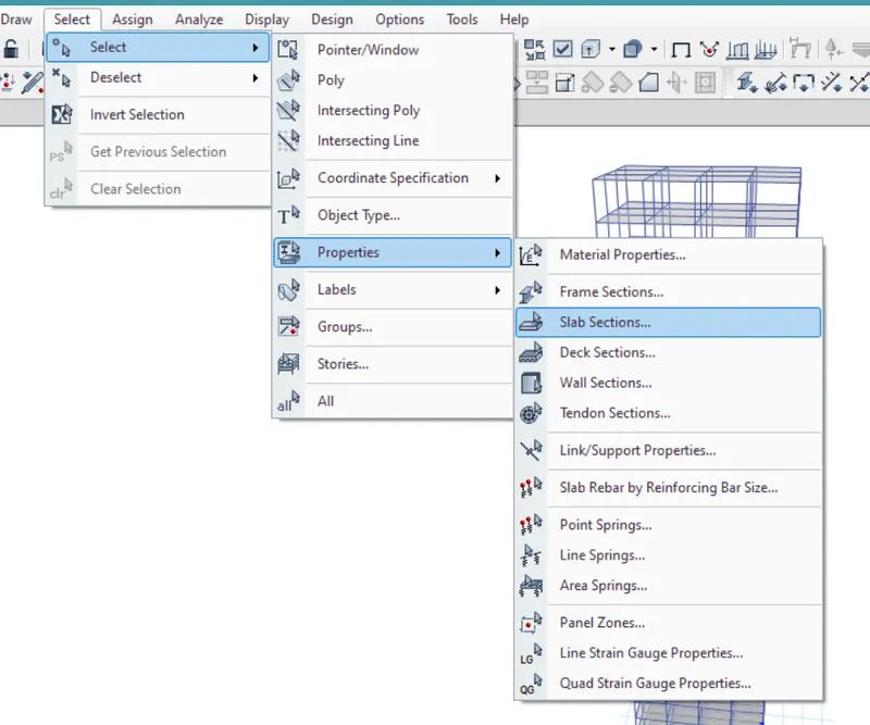
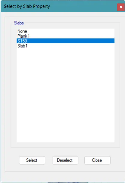
- Go to select, and select all the slabs.
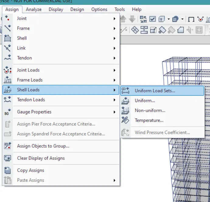
- Then click on the assign tab.
- Go to the shell loads.
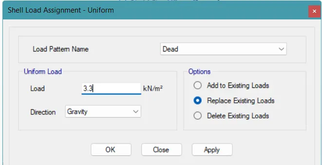
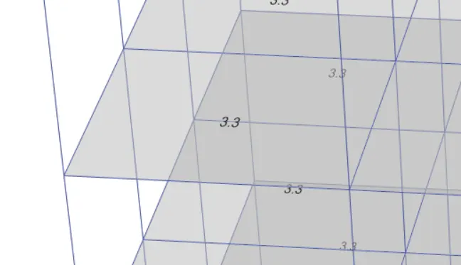
- Replace the shell load value of 3KN/m² with 3.3KN/m².
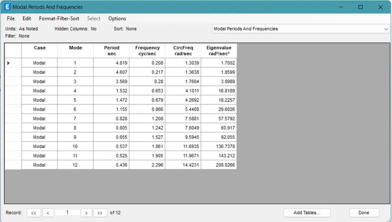
- Again analyze the model and note down the modal analysis values for it.
- Model K:
- Now create a copy of the Model J file.
- Go to select, and select all the slabs.
- Then click on the assign tab.
- Go to the shell loads.
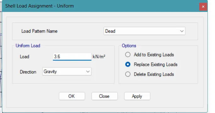
- Replace the shell load value of 3.3KN/m² with 3.6KN/m².
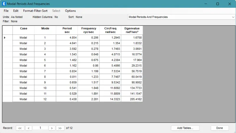
- Again analyze the model and note down the modal analysis values for it.
RESULTS:
| Question 1 | Model | Period (T) | Conclusion |
| Effect of stiffness on T | Model E | 1.952 s | As Model F has only the C600x600 type columns, it is stiffer, compared to the Model E having C400x400 and C600x600, both type columns |
| Model F | 1.735 s | ||
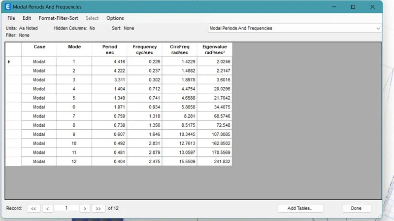
| Effect of stiffness on T | Model G | 4.416 s | Even though, there are three different sizes of columns in Model G, while only one type of column in Model H, the arrangements of the columns make the modal analysis of it exactly the same. |
| Model H | 4.416 s |
| Question 2 | Model | Time Period (T) | Conclusion |
| Effect of mass on T | Model H | 4.416 s | All three models have the same cross-section size of the columns. But the live load on the slab is variating. The lesser the live load, lesser is the time period. |
| Model J | 4.819 s | ||
| Model K | 4.854 s |
| Question 3 | Model | Time Period (T) | Conclusion |
| Effect of Building Height on T | Model A | 0.500 s | All the four buildings are of different heights. As the height pf the building increase the time period also increases. |
| Model B | 1.143 s | ||
| Model F | 1.735 s | ||
| Model H | 4.416 s |
| Question 4 | Model | Time Period(T) | Conclusion |
| Effect of Column Orientation on T | Model B | 1.143 s | All the three buildings are of the same height but differ in the arrangements of the columns. The best option is the B one here as rest two show more deflection in the direction of the smaller dimension of the column. |
| Model C | 1.145 s | ||
| Model D | 1.120 s |
| Question 5 | Model | Flexural Stiffness of | Time Period(T) | Conclusion |
| Effect of Flexural Stiffness of Structural Elements on mode shapes | Model B | Normal | 1.143 s | When the flexural stiffness is brought down to 10% the time period increases. |
| Zero Inertia | 2.899 s |
| Question 6 | Model | Axial Stiffness at | Time Period (T) | Conclusion |
| Effect of Axial Stiffness of Vertical Members on mode shapes | Model H | Normal | 4.416 s | When the axial stiffness is brought down to 10% the time period increases |
| Close to zero | 5.991 s |
| Question 7 | Model | Degree of Fixity | Time Period (T) | Conclusion |
| Effect of Degree of Fixity at column based on mode shape | Model B | Normal | 1.143 s | When the supports are changed to fixed, the time period decreases. |
| Close to zero | 1.039 s |