Project 1_Comparative study of different storey buildings for Seismic forces
AIM:
To do a comparative study of different storey buildings for Seismic forces
Introduction:
Earthquake causes shaking of the ground. So, a building resting on it will experience motion at its base. From Newton’s First Law of Motion, even though the base of the building moves with the ground, the roof has a tendency to stay in its original position. But since the walls and columns are connected to it, they drag the roof along with them. This is much like the situation that you are faced with when the bus you are standing in suddenly starts; your feet move with the bus, but your upper body tends to stay back making you fall backwards!! This tendency to continue to remain in the previous position is known as inertia. In the building, since the walls or columns are flexible, the motion of the roof is different from that of the ground.
The Inertia Force experienced by the roof is transferred to the ground via the columns, causing forces in columns. These forces generated in the columns can also be understood in another way. During earthquake shaking, the columns undergo relative movement between their ends. In Figure 2, this movement is shown as quantity u between the roof and the ground. But, given a free option, columns would lie to come back to the straight vertical position, i.e., columns resist deformations. In the straight vertical position, the columns carry no horizontal earthquake force through them. But, when forced to bend, they develop internal forces. The more is the relative horizontal displacement of u between the top and bottom of the column, larger is this internal force in columns. Also, the stiffer the columns are (i.e., bigger is the column size), larger is this force. For this reason, these internal forces in the columns are called stiffness forces. In fact, the stiffness force in a column is the column stiffness times the relative displacement between its ends.
Earthquake causes shaking of the ground in all three directions – along the two horizontal directions (X and Y, say), and the vertical direction (Z, say) (Figure 3). Also, during the earthquake, the ground shakes randomly back and forth (- and +) along each of these X, Y and Z directions. All structures are primarily designed to carry the gravity loads, i.e., they are designed for a force equal to the mass M (this includes mass due to own weight and imposed loads) times the acceleration due to gravity g acting in the vertical downward direction. (-Z)
Procedure:
BUILDING A:
Following the steps mentioned below for Building A ,The features are as follows:
Two-story building
Beam: 300 X 400 mm
Column: 400 x 400 mm
Grade M30, Fe415
Brick wall load= 10KN/m
Live load 3KN/m^2
Open etabs and select new model
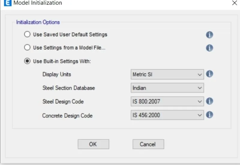
Model intialization interface appears and select USE BUILD IN SETTINGS and make the below mentioned settings
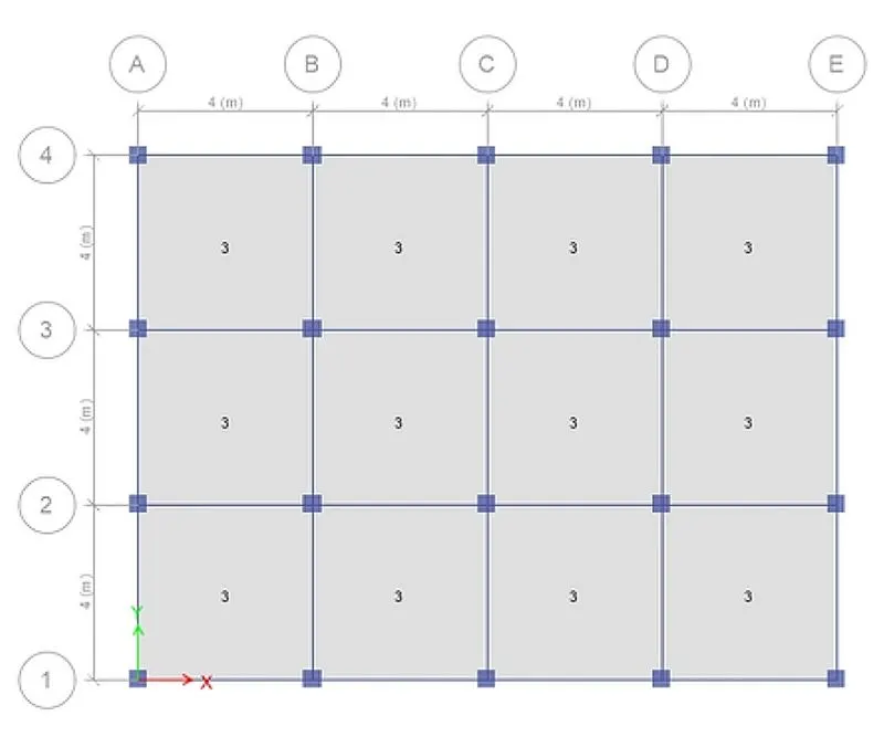
An interface appears as shown in picture. Click the custom grid spacing and maintain the spacing as 4m in both x and y direction
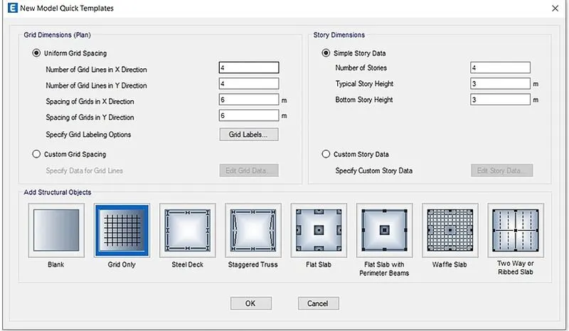
In X direction draw 5 grids and in Y draw 4 grids
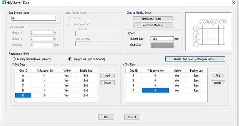
Click OK, a box appears
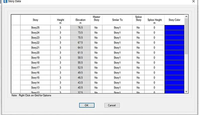
Enter the stories upto 2 maintaining height of 3m expect for base to plinth which is at 1.5m and 1st storey is entered as master story
STEP 2:
Now go to define option in toolbar and select material properties, and enter the following .
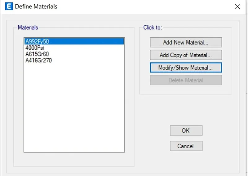
Go to add new material property option for M30 concrete
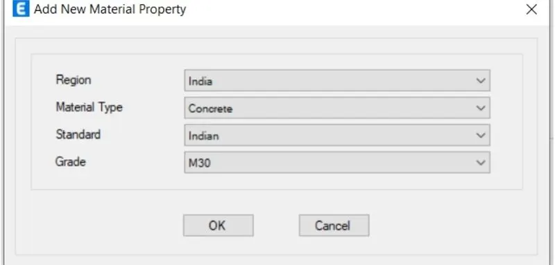
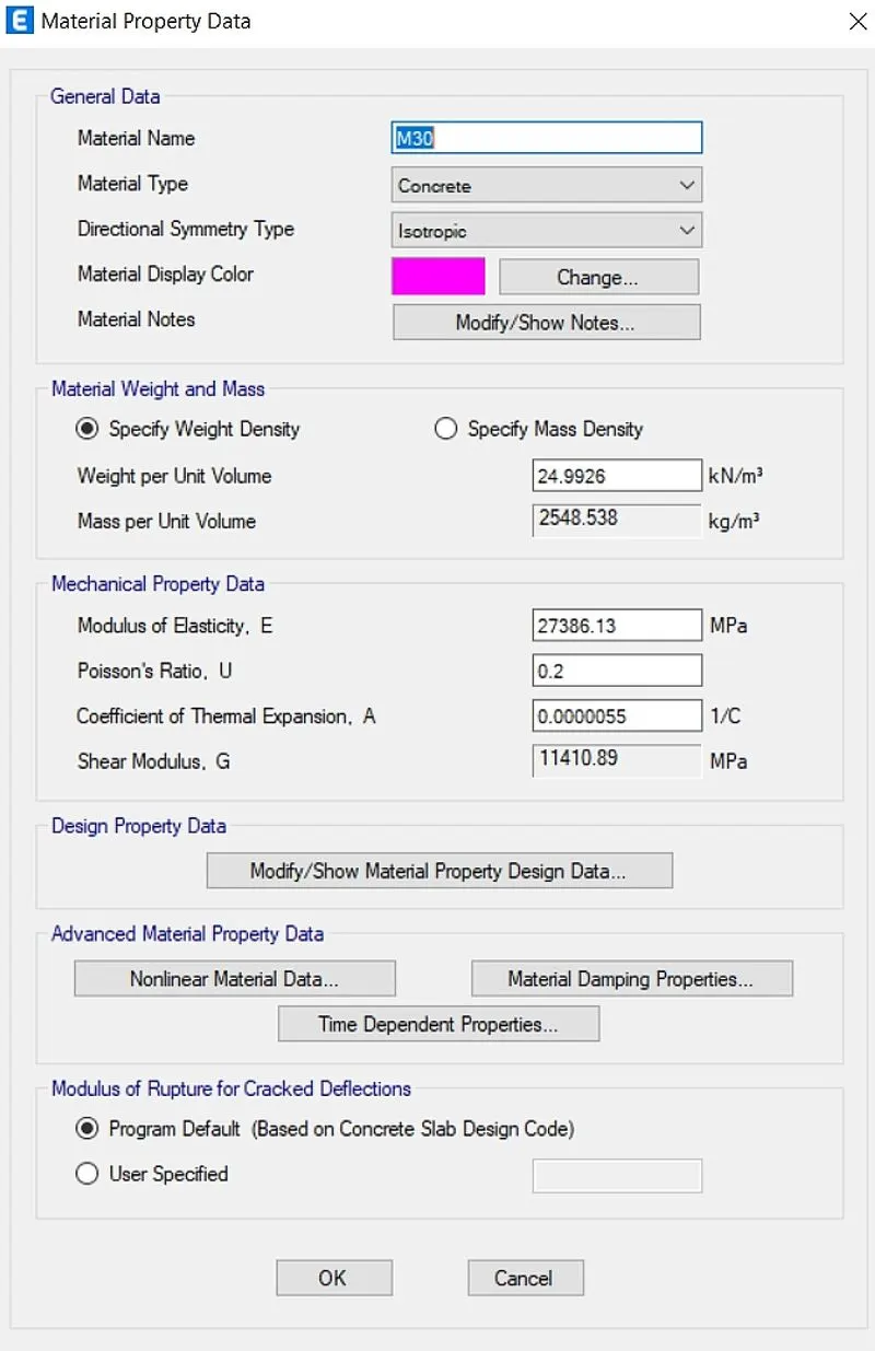
The properties of M30 as per IS code defined before gets displayed
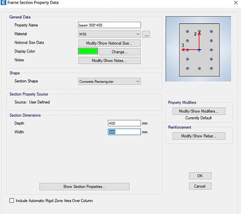
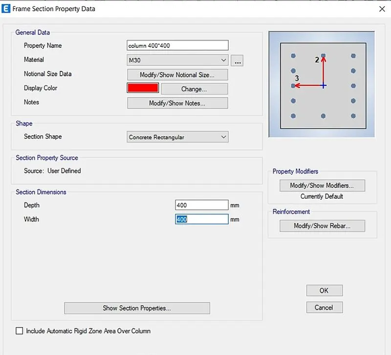
Now go to selection properties and enter the size of beam column and slab
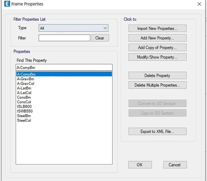
For concrete beam of size 300 x 400mm
For column of size 400 x 400mm
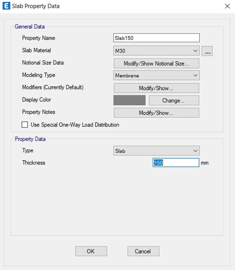
Go to Define > Section properties > slab section
Enter the data as shown
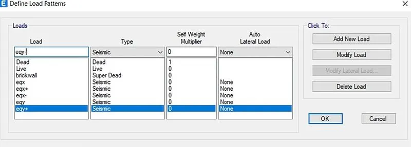
Now go to the load pattern, and enter the loads as shown
Now select the quick draw column from the screen and place the columns at each grid
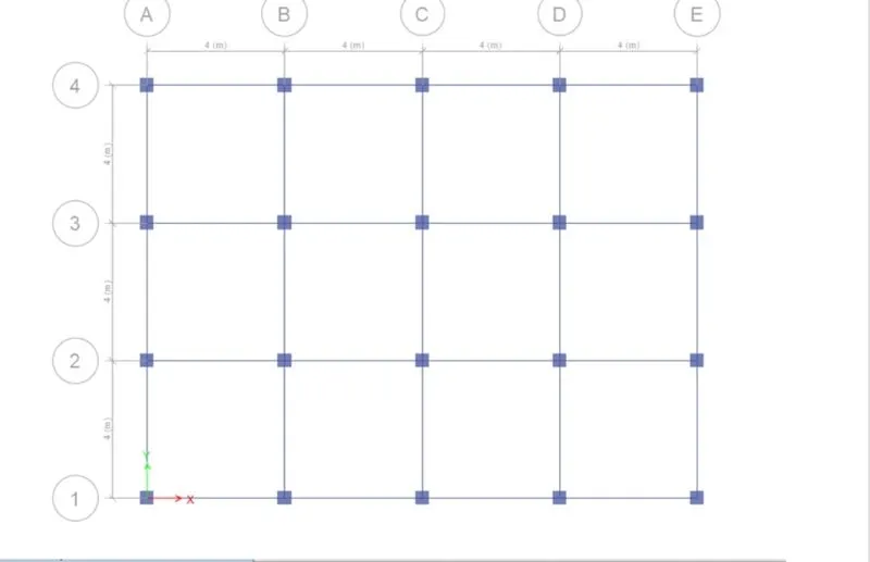
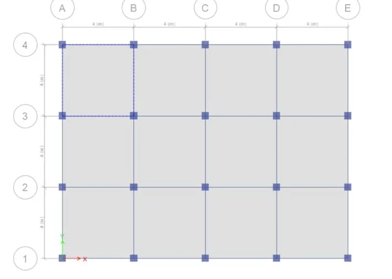
Similarly place the beams and slabs .Place the slabs in all floors except plinth
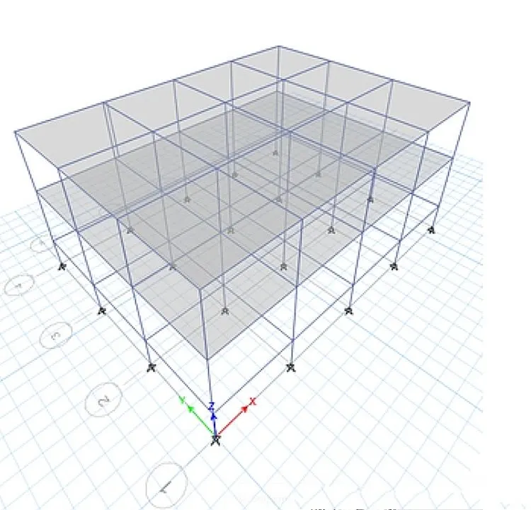
3d presentation of the building is shown below:
STEP 3:
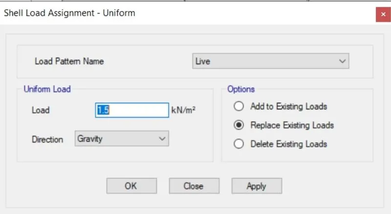
Now assign the load to roof slab,select all the slabs and go to assign option
Select the load as live and value as 1.5KN/m^2
The value in the plan view is shown as below
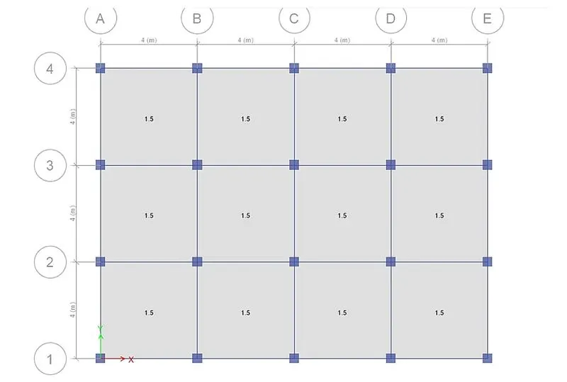
For other floors assign 3KN/m^2
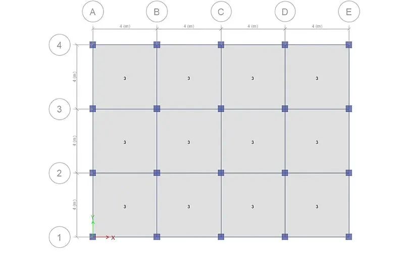
Now assign the load to all beam of 10KN/m^2
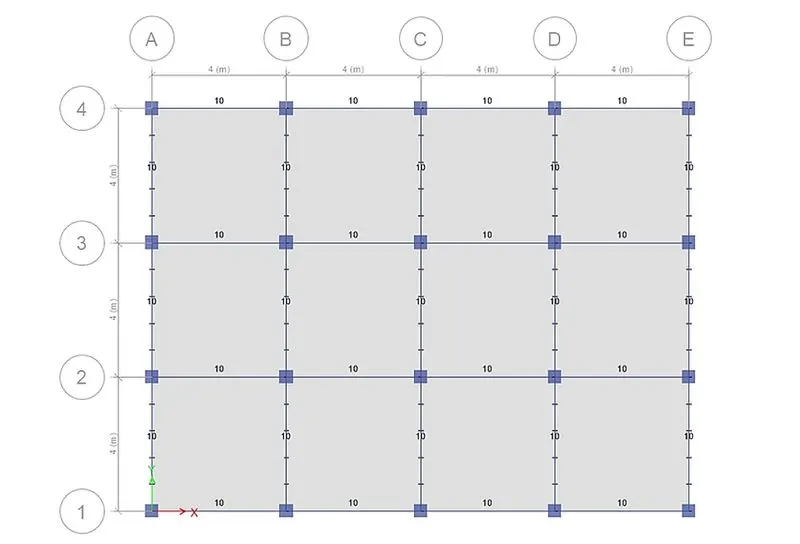
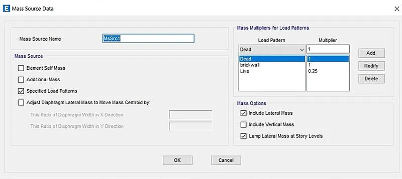
Now go to define option and select mass source and assign the mass source as shown
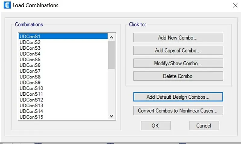
Go to the load combination and select modify, alist of combination appears
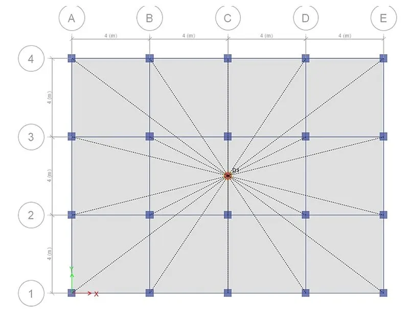
Go to the shells from assign and then select diaphgram, assign as D1

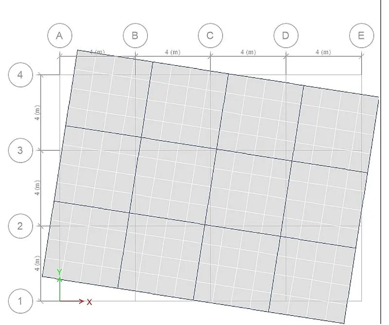
In the plan view, diaphgram is shown as below
STEP 4:
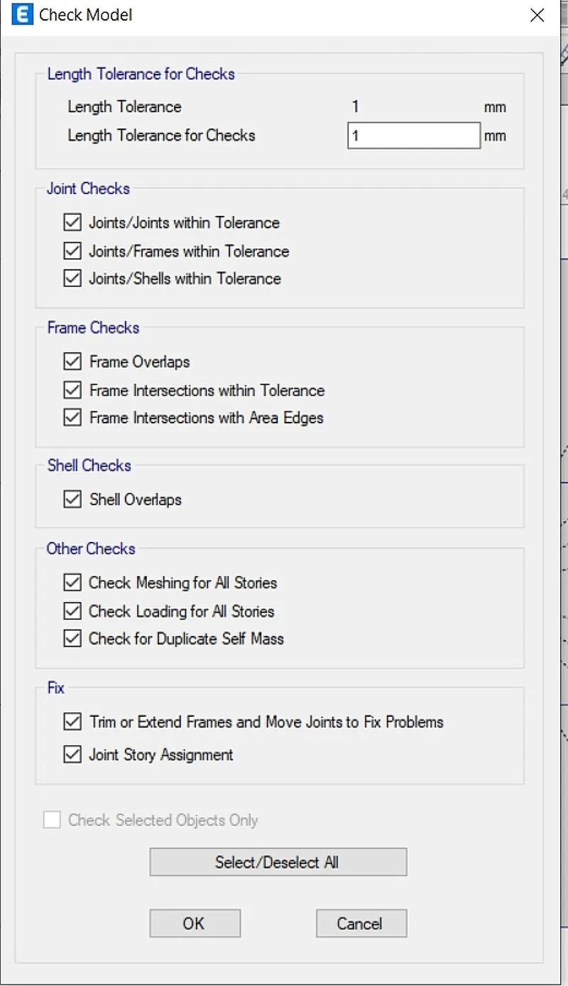
Now go to the analyse and check model
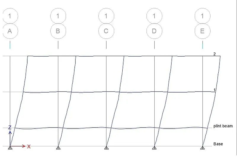
Analysis
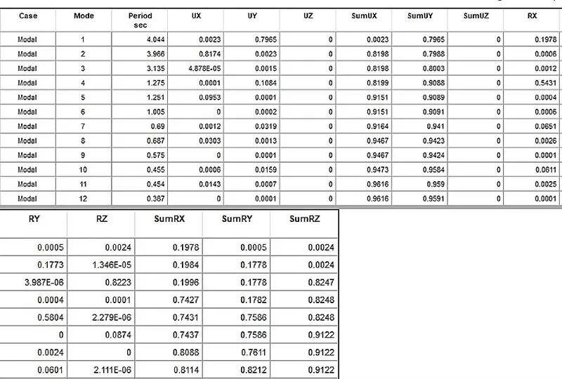
Model participating mass ratio
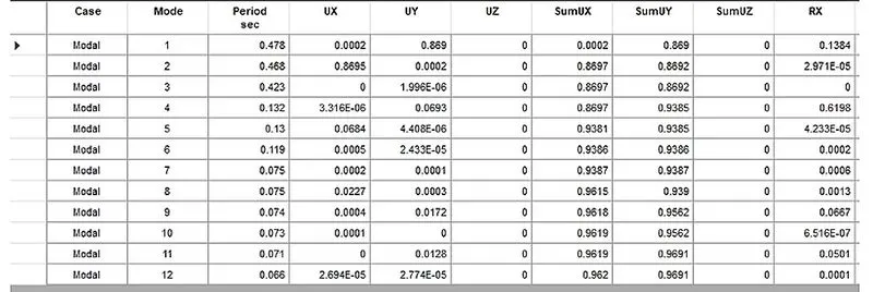
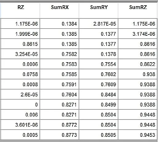
Mode2 : T=0.465 seconds
BUILDING B:
Save it for the Building B and now model the building as per below mentioned features:
Five-story building
Beam: 300 X 400 mm
Column: 400 x 400 mm
Grade M30, Fe415
Brick wall load= 10KN/m
Live load 3KN/m^2
To create 5 stories ,Go to edit> edit stories> add stories> refresh view
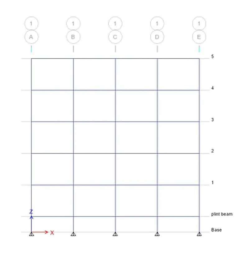
Check for the loads again
3D view of the model is shown below
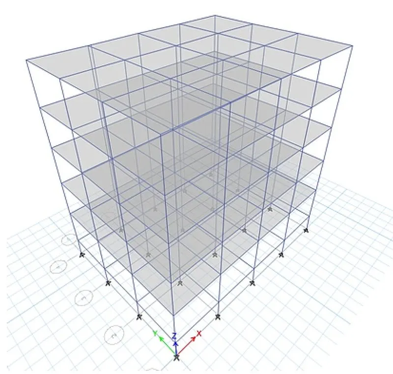
Run the analysis
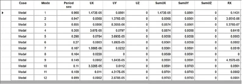
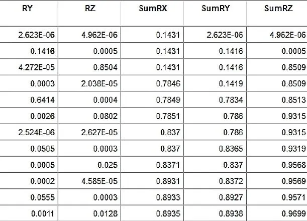
Analysis
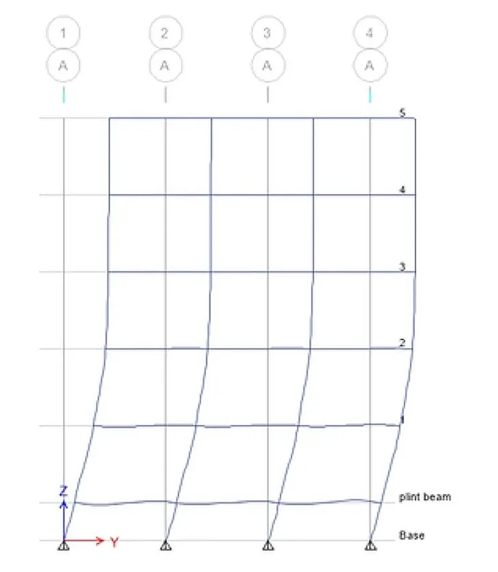
Model participating mass ratio
BUILDING C:
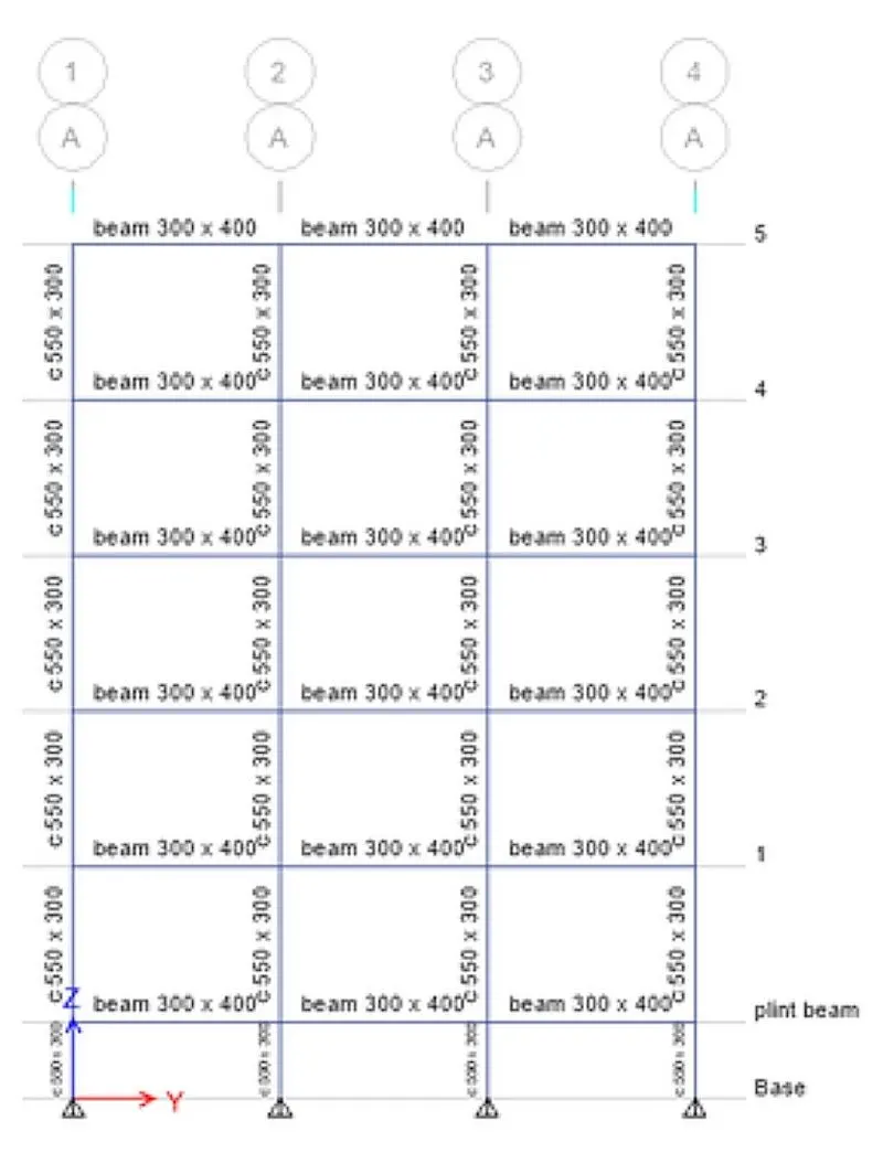
Save it for the Building C and now model the building as per below mentioned features
Five-story building
Beam: 300 X 400 mm
Column: 550 x 300 mm
Grade M30, Fe415
Brick wall load= 10KN/m
Live load 3KN/m^2
3D view of the model is shown below
Analysis
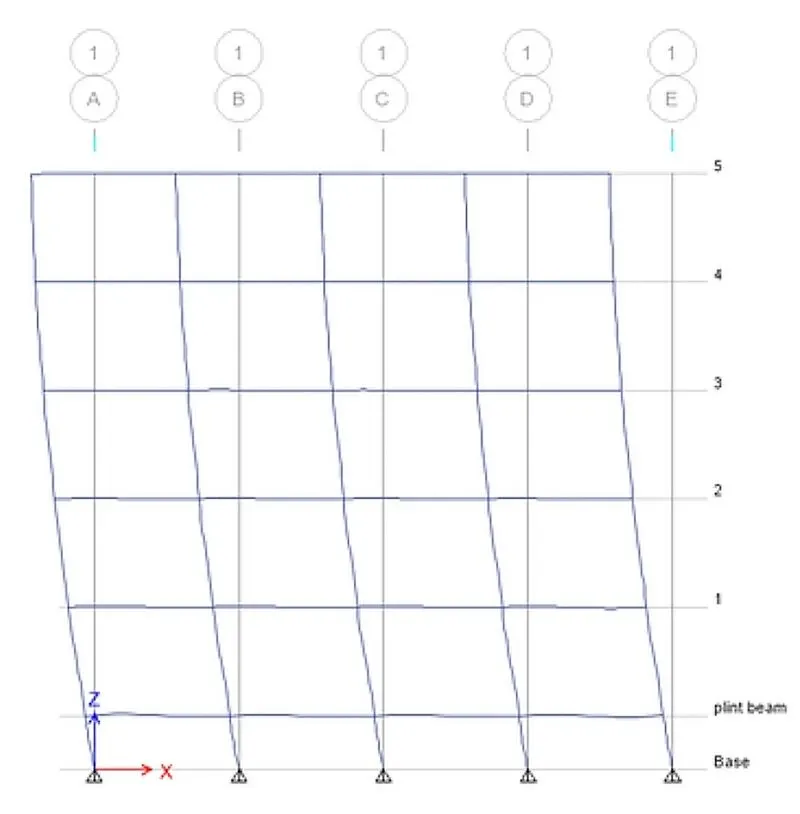
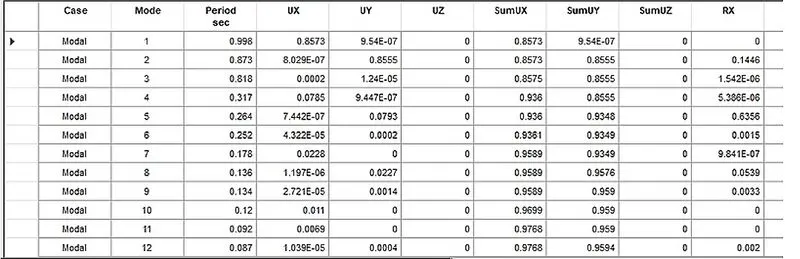
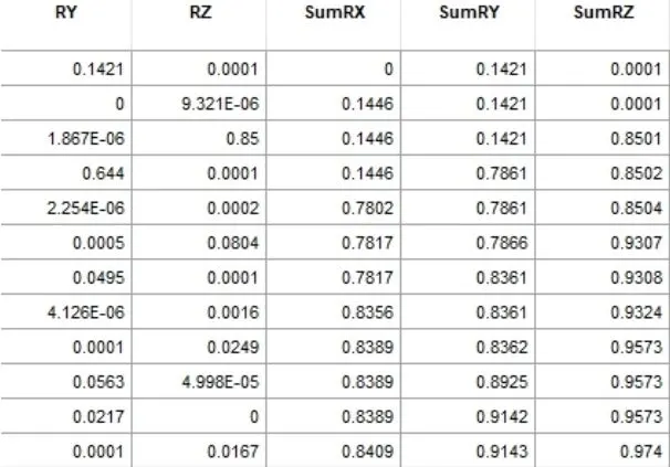
Model participating mass ratio
BUILDING D:
Save it for the Building D and now model the building as per below mentioned features
Five-story building
Beam: 300 X 400 mm
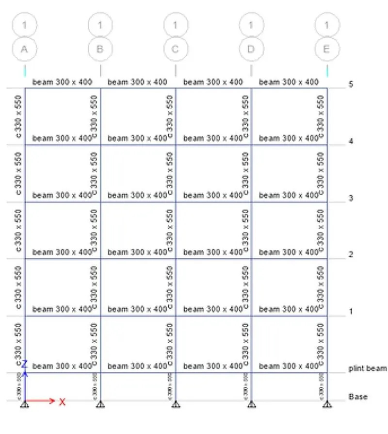
Column: 330 x 550 mm
Grade M30, Fe415
Brick wall load= 10KN/m
Live load 3KN/m^2
3D view of the model is shown below
Analysis
Model participating mass ratio
BUILDING E:
Save it for the Building E and now model the building as per below mentioned features
Ten-story building
To create 5 stories ,Go to edit> edit stories> add stories> refresh view
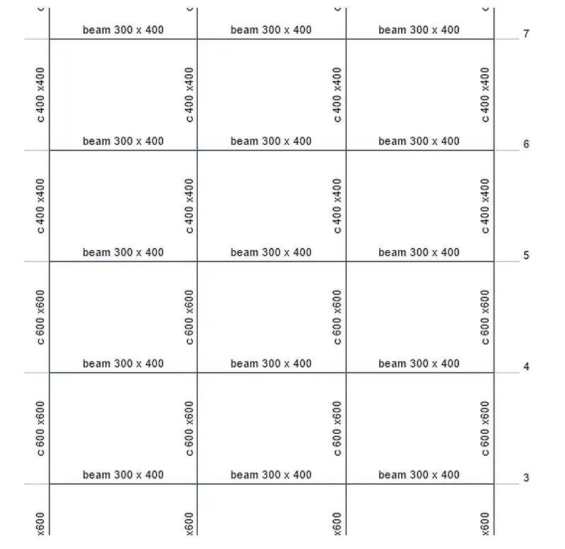
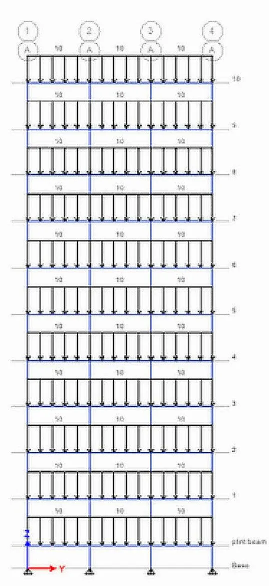
Beam: 300 X 400 mm
Column: Bottom 5 are 600 x 600 mm
:Upper 5 are 400 x 400 mm
Grade M30, Fe415
Brick wall load= 10KN/m
Live load 3KN/m^2
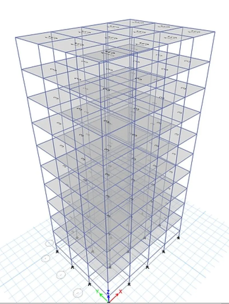
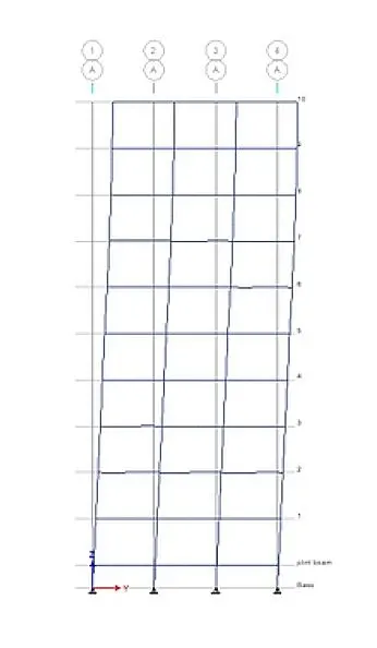
3D view of the model is shown below
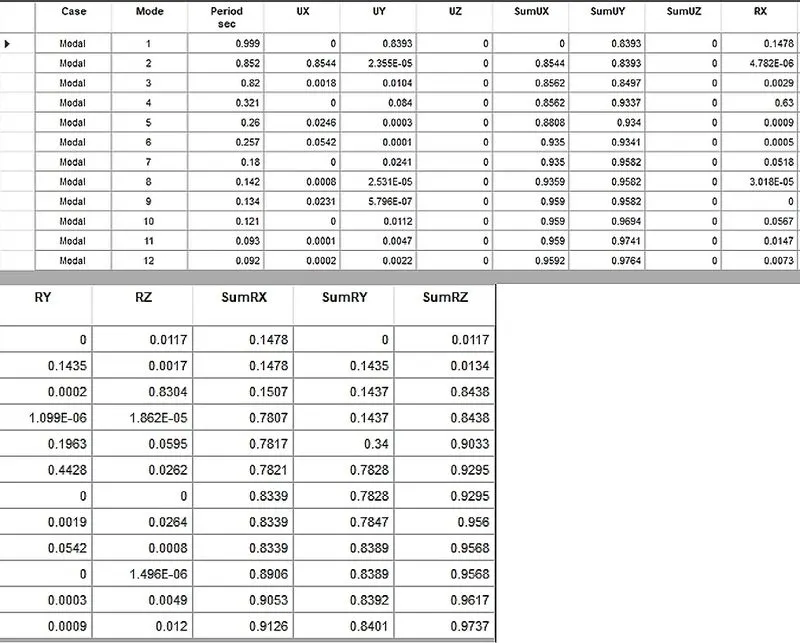
Analysis
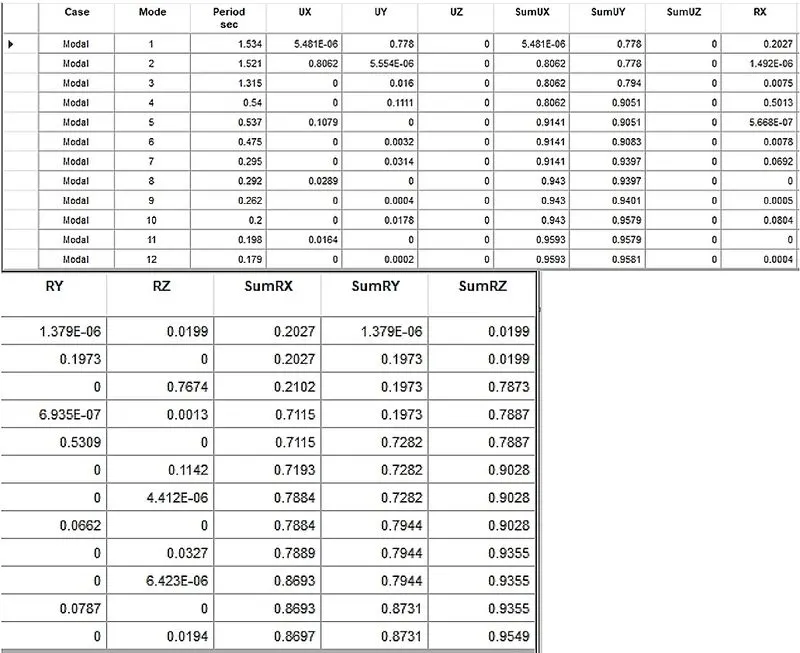
Model participating mass ratio
BUILDING F:
Save it for the Building F and now model the building as per below mentioned features
Ten-story building
Beam: 300 X 400 mm
Column: 600 x 600 mm
Grade M30, Fe415
Brick wall load= 10KN/m
Live load 3KN/m^2
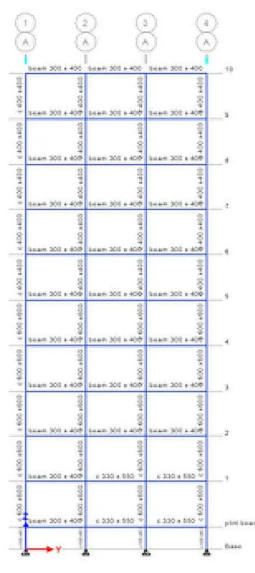
Analysis
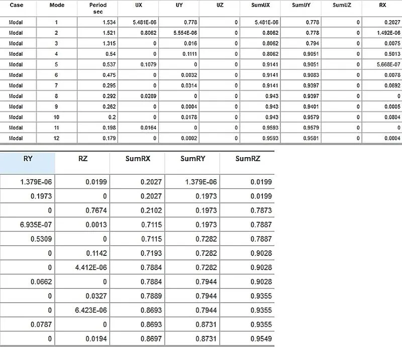
Model participating mass ratio
BUILDING G:
Save it for the Building G and now model the building as per below mentioned features
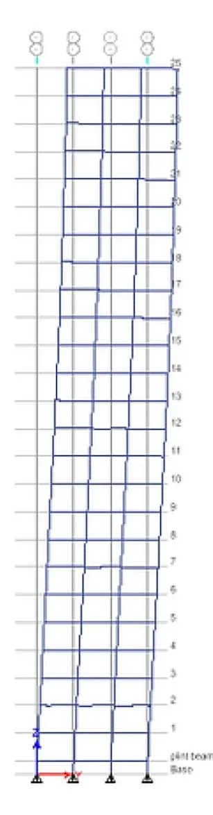
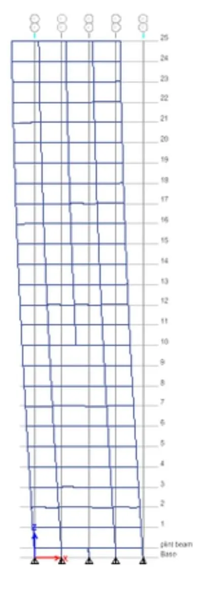
Twenty five-story building
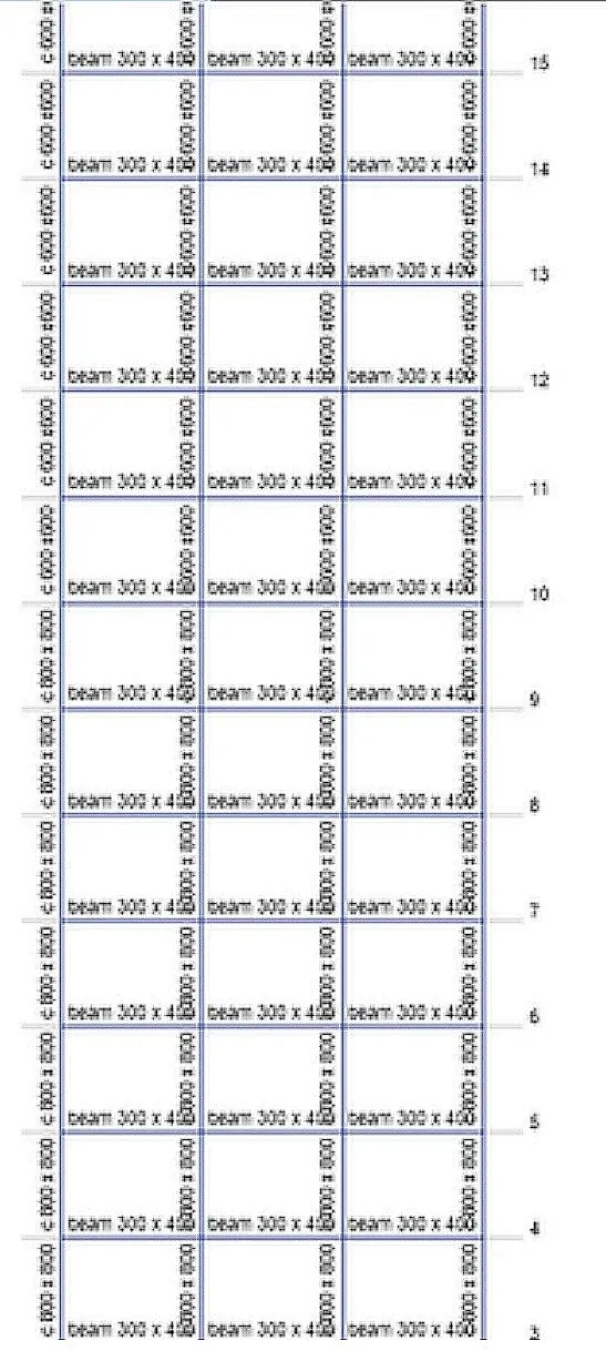
Beam: 300 X 400 mm
Column: Bottom 10 are 800 x 800 mm
:Upper 10 are 600 x 600 mm
: Top upper 5 are 400 x 400 mm
Grade M30, Fe415
Brick wall load= 10KN/m
Live load 3KN/m^2
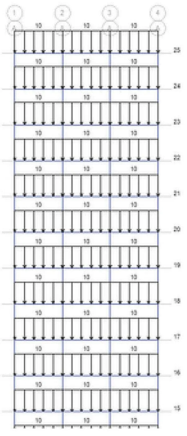
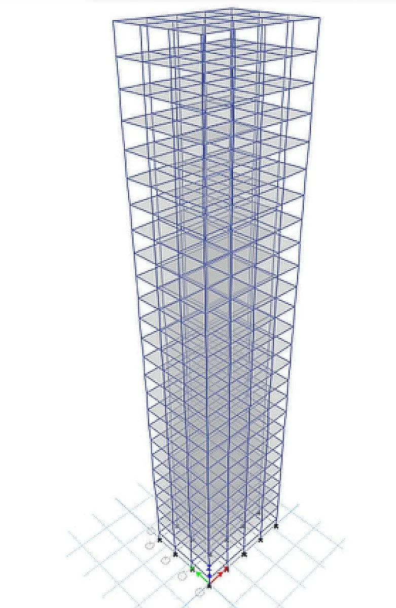
3d view is as follows
Analysis
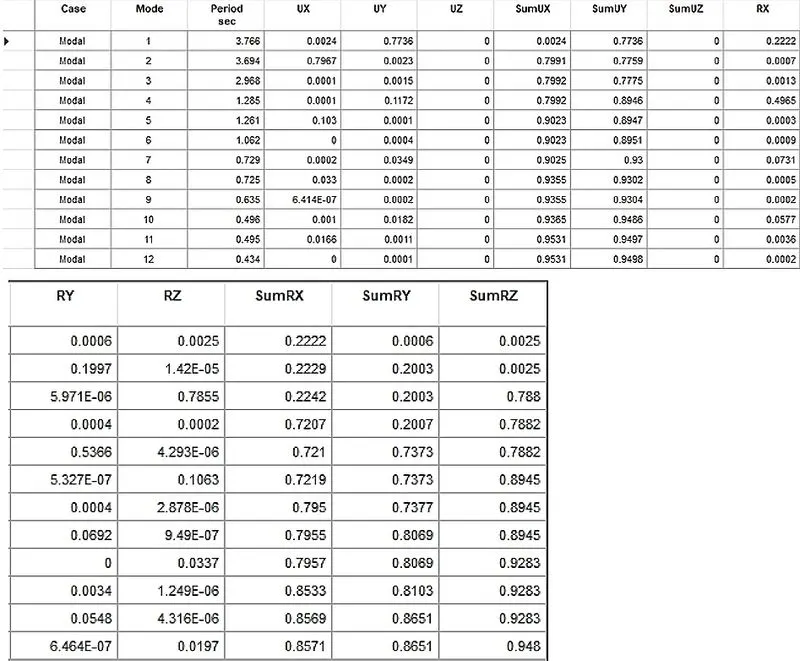
Model participating mass ratio
BUILDING H:
Save it for the Building H and now model the building as per below mentioned features
Twenty five-story building
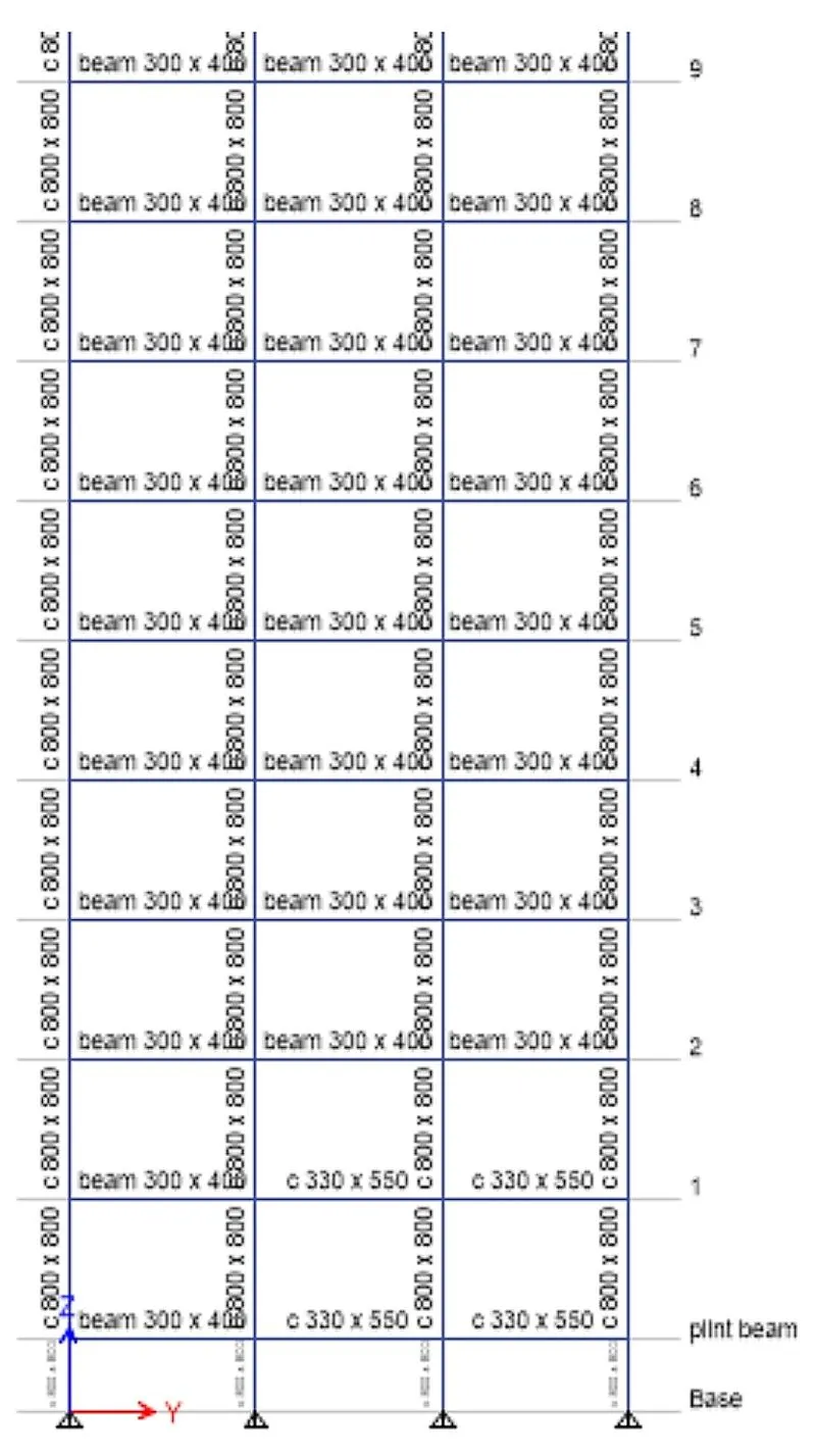
Beam: 300 X 400 mm
Column: 800 x 800 mm
Grade M30, Fe415
Brick wall load= 10KN/m
Live load 3KN/m^2
3D view is as follows:
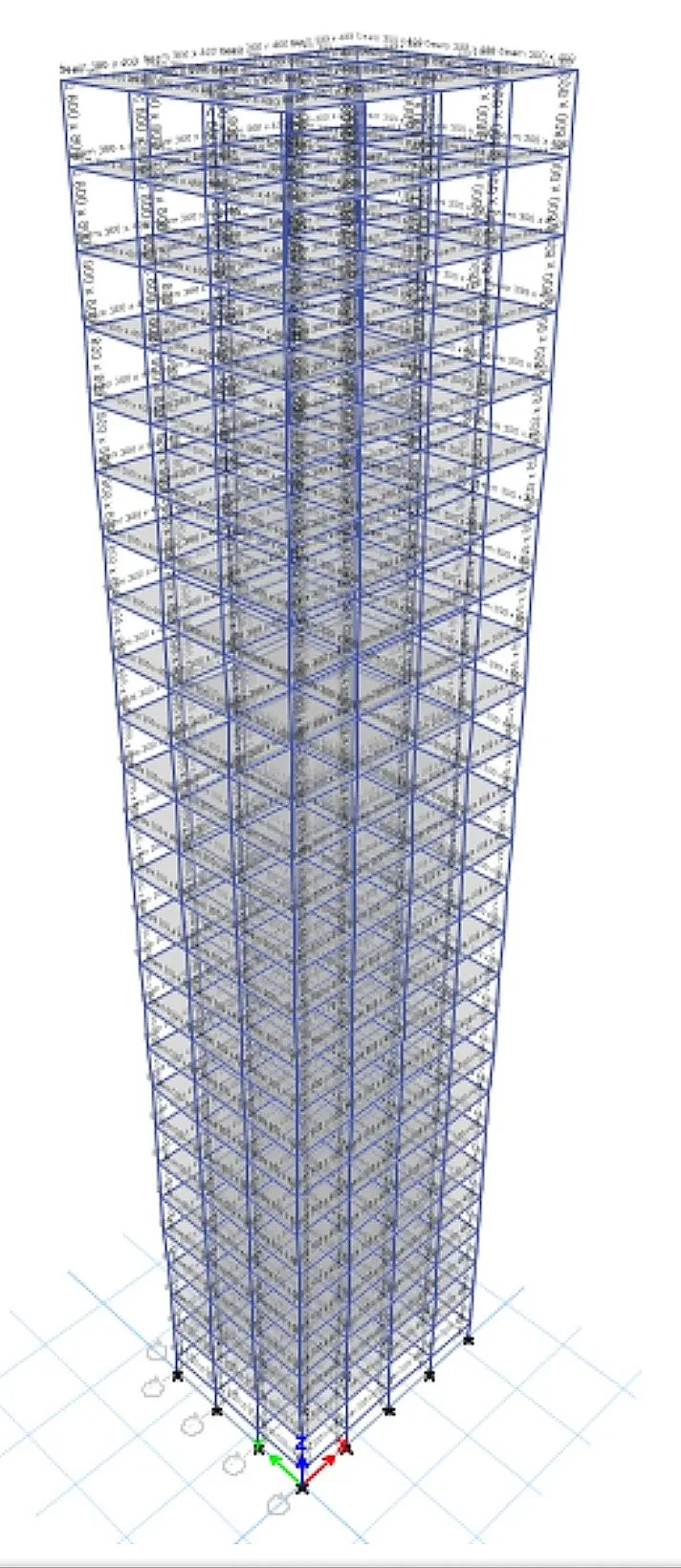
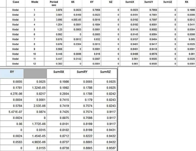
Analysis
Model participating mass ratio
BUILDING I:
Save it for the Building I and now model the building as per below mentioned features
Twenty five-story building
Beam: 300 X 400 mm
Column: 800 x 800 mm
Grade M30, Fe415
Brick wall load= 10KN/m
Live load 3KN/m^2
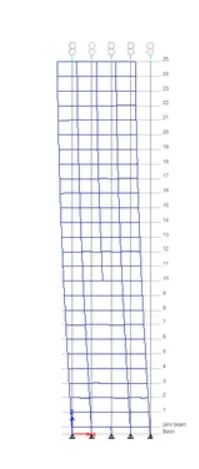
3D view is shown below:
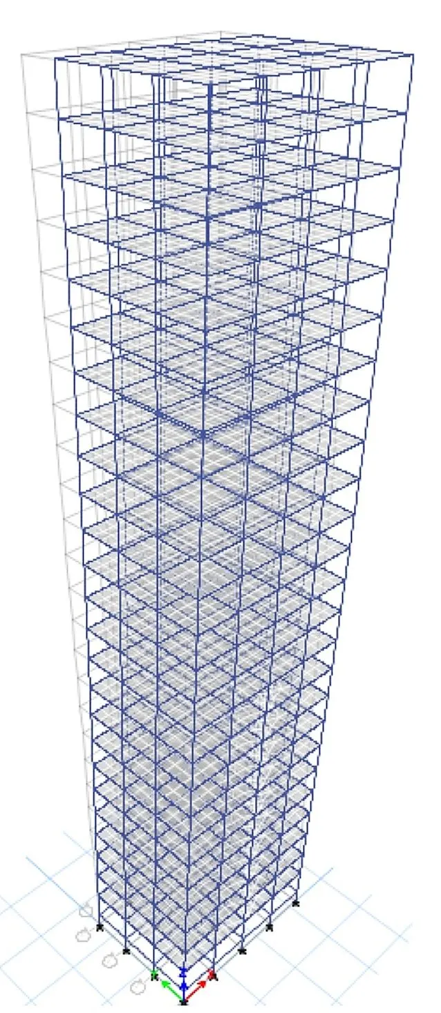
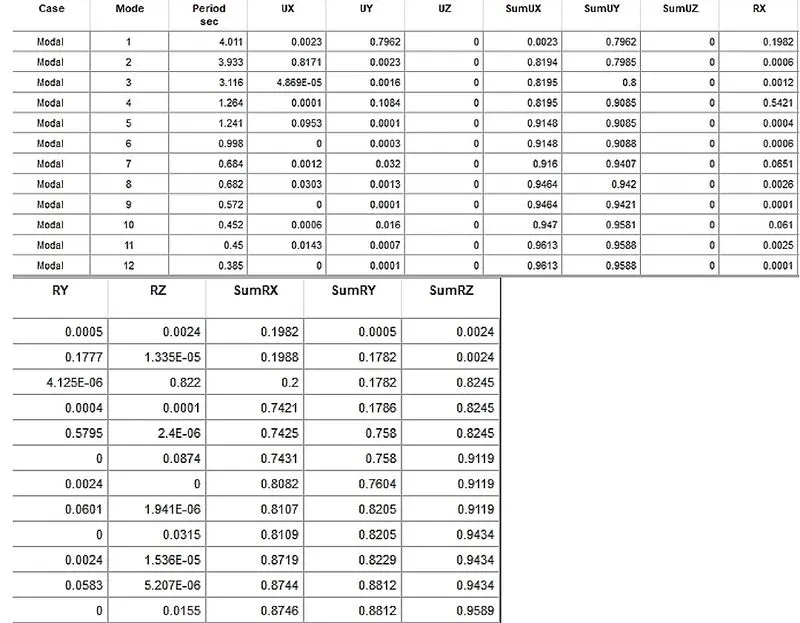
wih imposed mass 10% larger than h, therefore the imposed mass is 0.35
Analysis
Model participating mass ratio
BUILDING J:
Save it for the Building J and now model the building as per below mentioned features
Twenty five-story building
Beam: 300 X 400 mm
Column: 800 x 800 mm
Grade M30, Fe415
Brick wall load= 10KN/m
Live load 3KN/m^2 (60%)
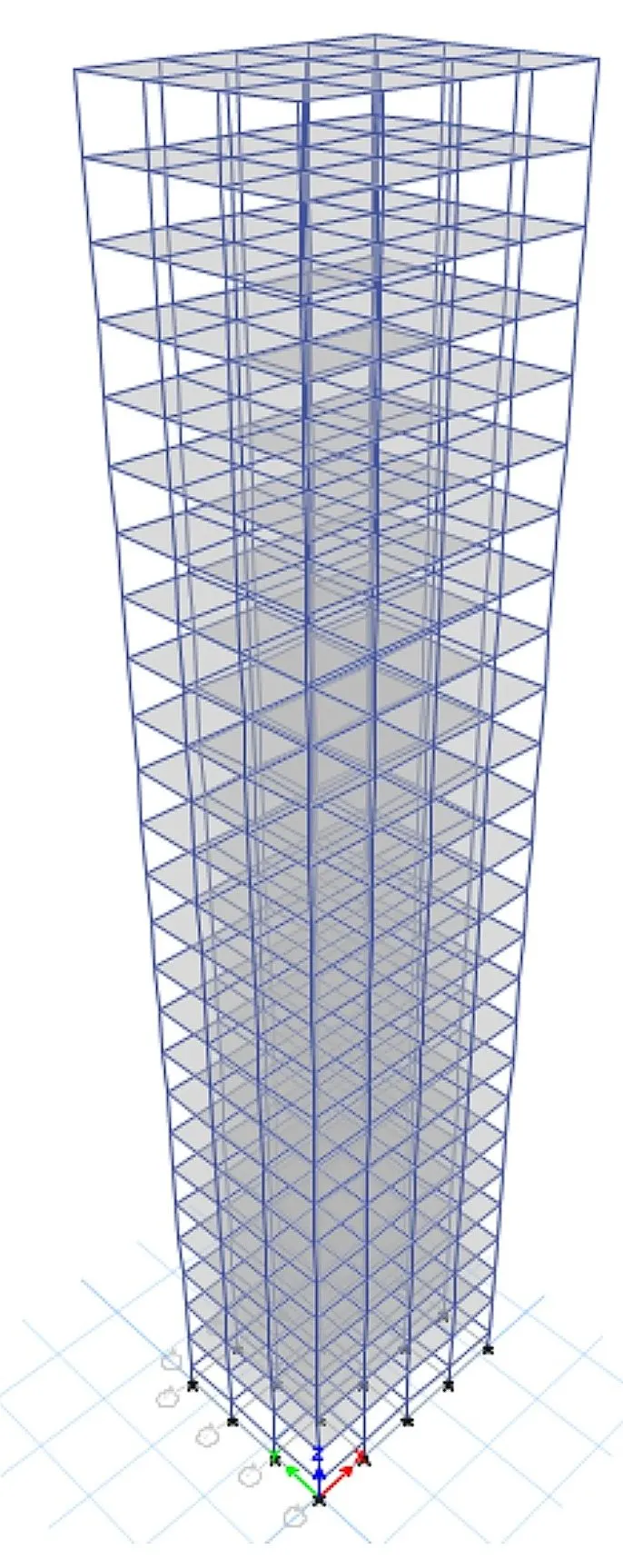
wih imposed mass 20% larger than h, therefore the imposed mass is 0.45
3D view is shown as:
Analysis
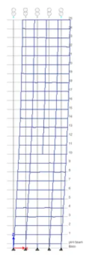
Model participating mass ratio
RESULT:
Effect of stiffness
Natural periods of e and f
- e=(`t_(y)=1.53 , t_(y)=1.52`)
- f=(`t_(y)=1.53 , t_(y)=1.53`)
There is only marginal difference in the fundamental natural period
Natural periods of g and h
- `g=(t_(y1)= 3.7 , t_(x2) = 3.6 )`
- `h=(t_(y2)= 3.9 , t_(x1) = 3.9 )`
There is only marginal difference in the fundamental natural period
Effect on mass
H,J and K have the buildings become more flexible due to the increase imposed mass
Effect on building height:
Fundamental natural time periods of buildings increase with height
Effect of column orientation on T
There is only marginal difference in the fundamental natural period when compared with c and d