Project 1_Comparative study of different storey buildings for Seismic forces
Objective of this project is to:
a) Know how to extract different seismic responses for a structure.
b) How to easily alter certain properties in a Etabs model.
c) Know the factor influencing the dynamic characteristics of building.
d) Know the factors influencing time period of building.
e) Know the factors influencing mode shape of building.
f) Know the effect of stiffness, mass, building height and effect of column orientation.
g) Know the effect flexural stiffness, axial stiffness, degree of flexibility of column.
Procedure: Model A
1) Created the model A having 2 storey similar method as per challenge 6.
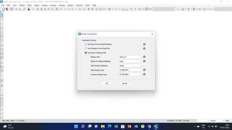
2) Open a new file in ETABS and change the parameters as done in challenge 6.
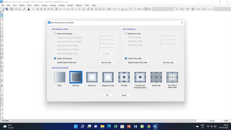
3) Change the grid system as per question and change the storey data as per question i.e 2 storey has to be created. Followed the steps as done in the challenge 6.
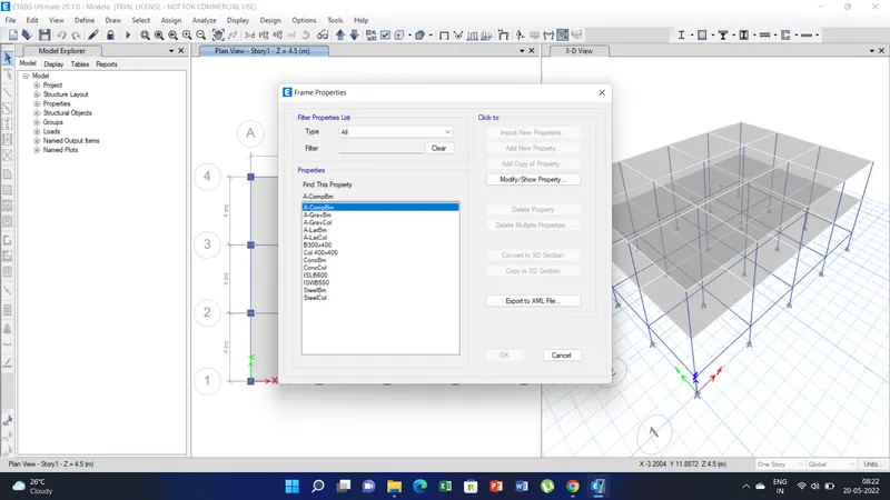
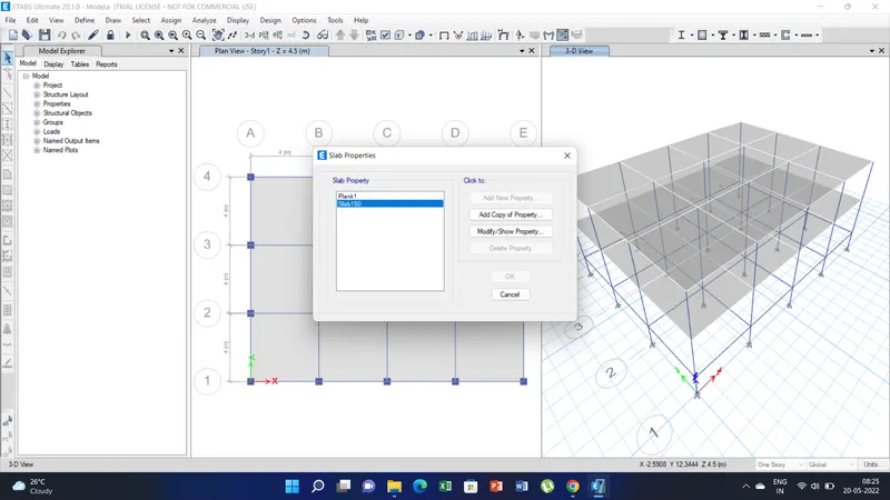
4) Now create the material properties under the frame section Column 400x400mm and beam 300 x400mm. Define the section properties for slab 150mm. Followed the similar steps as challenge 6.
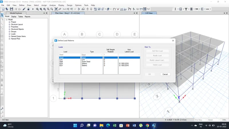
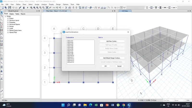
5) Define the load patterns as done in challenge 6 and also define the load combination.
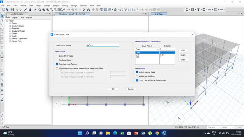
6) Create the Mass source as done in challenge 6.
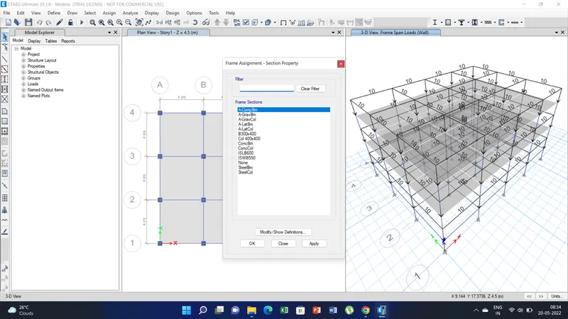
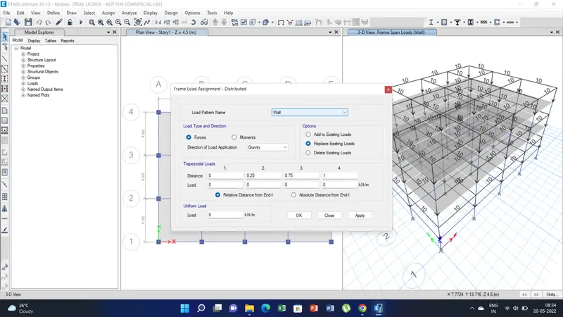
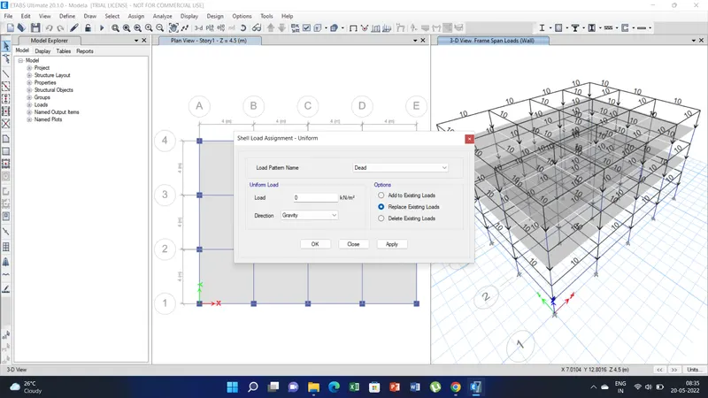
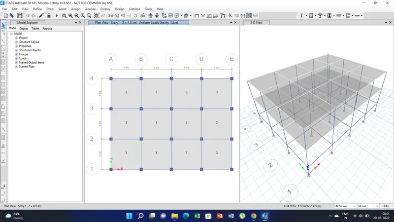
7)Select the beam and assign the section properties and assign the uniform loads and select the slab and assign the shell load.
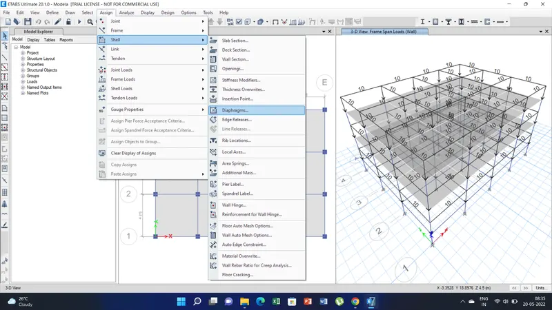
8) Also assign the shell diaphragam as done in challenge 6. and run the analysis.
Procedure: Model B
1) Now we have to create 5 storey model having same column dimension 400x400 mm.
2) In the model A go save as option and save the file as model B.
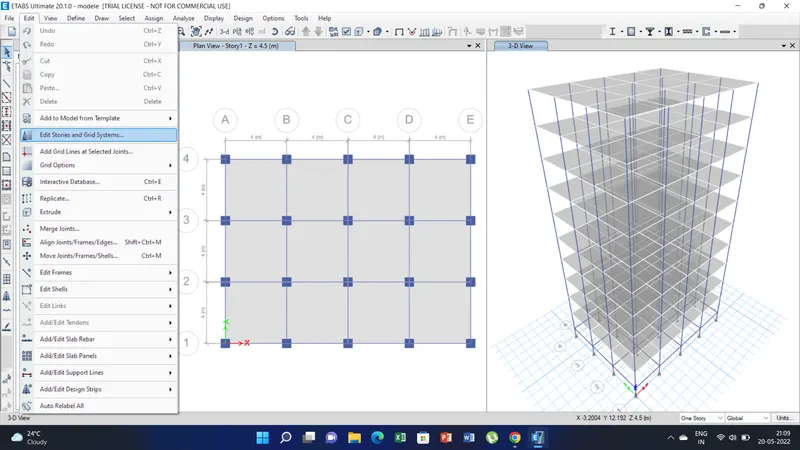
3) Now go edit tab and than click on edit storey and grid system.
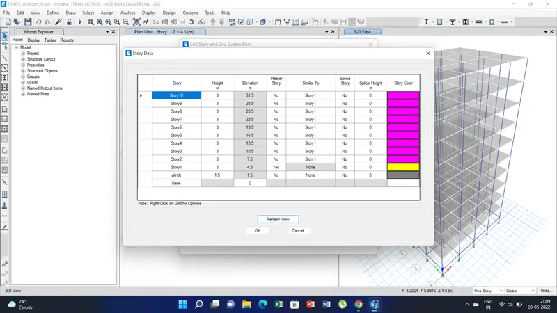
4) Than click on modify or show storey data. Than change the storey right click and add storey and create three storeys and make them similar to storey 1.
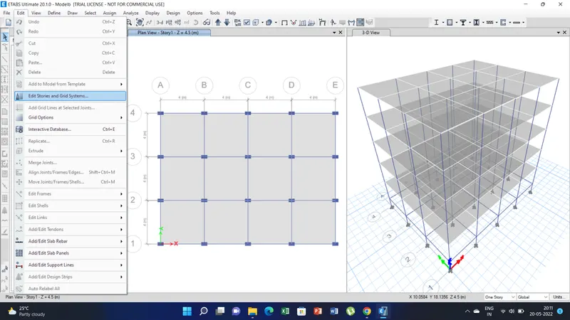
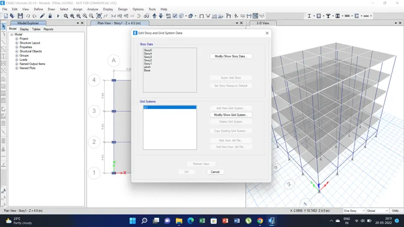
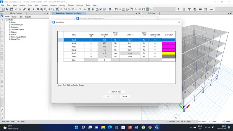
Procedure: Model C
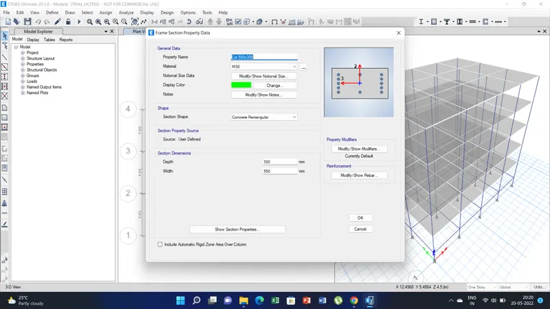
1) Here we have to change the column size to 550x300 and rotate the column along X direction.
2) First save the model B as Model C and tha go to the section properties-frame section under the define tab.
3) Select the column and click on the modify option. Than change the column property and column size to 550x300.
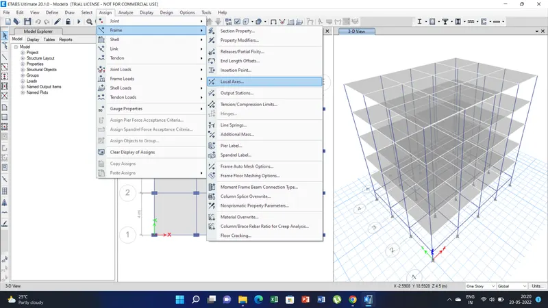
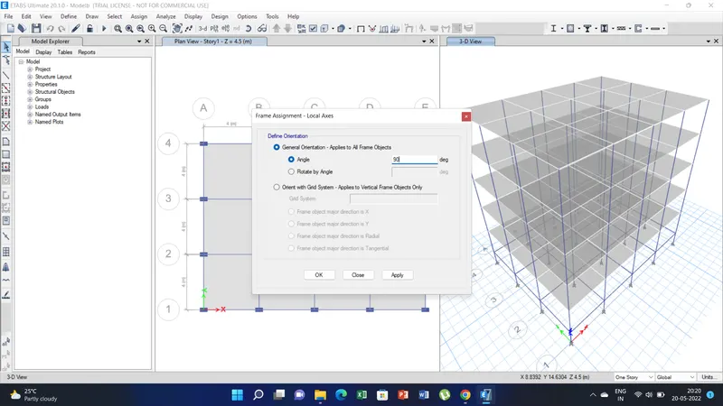
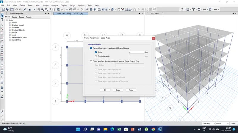
4) Now go to the assign tab-frame-local axis and than change the angle to 90 degree.

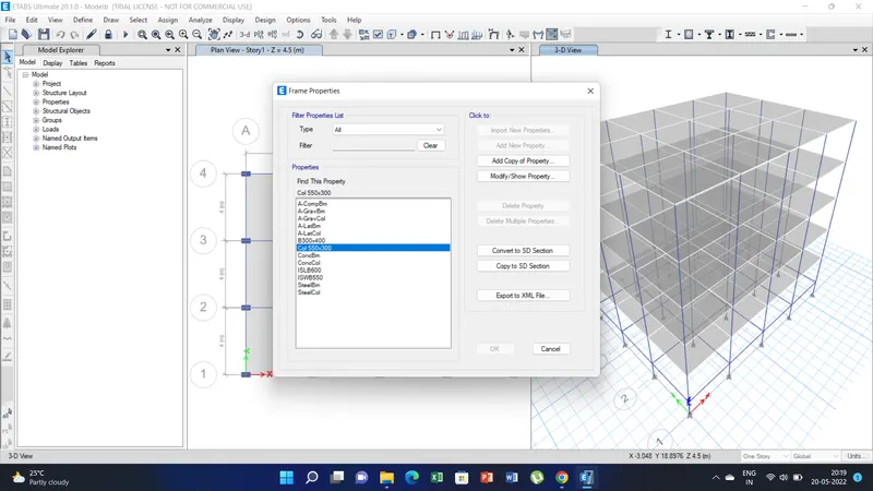
Procedure: Model D
1) Here we have to just orient the column along Y axis.
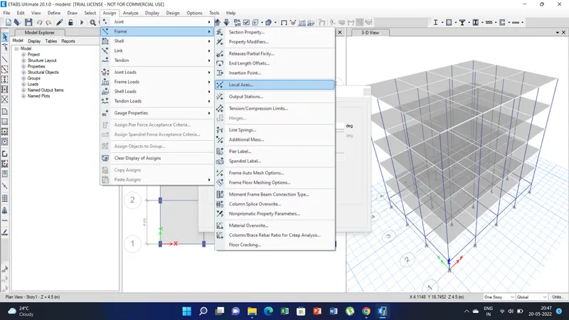
2) Go to the assign tab-frame-local axis.
3) Change the angle to 0 degree.
Procedure: Model E
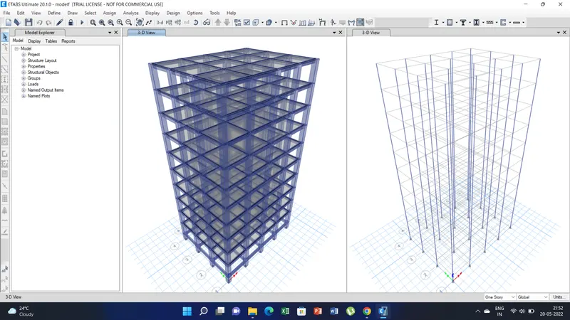
1) Here we have to create 10 storey and column size should be 600x600 at bottom 5 Storeys and 400x400 at upper 5 storeys.
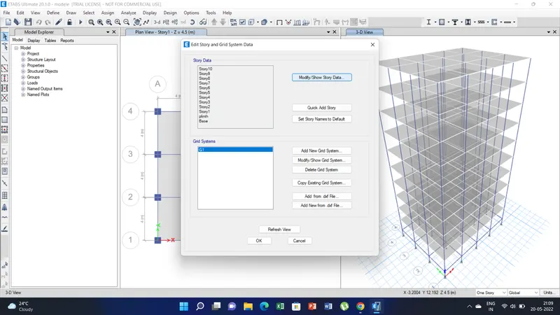
2) Go to the edit option and click on edit storey and grid system than click on the modify/show storey data.
3) Create storey right click and add storey. Create more five storeys and make them similar to storey 1.
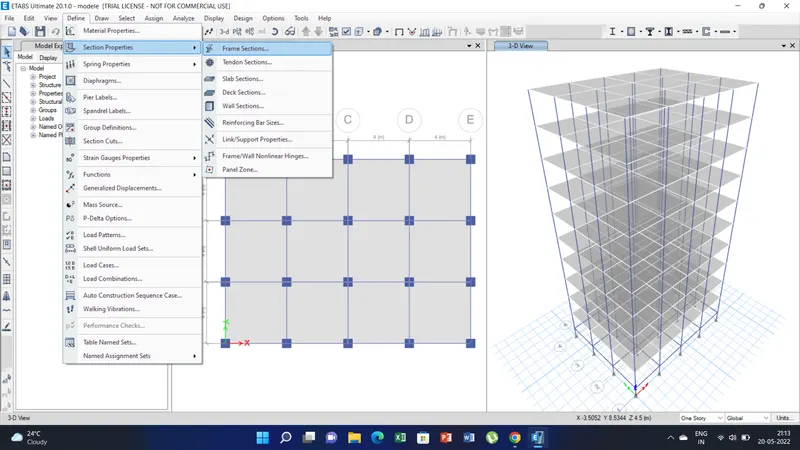
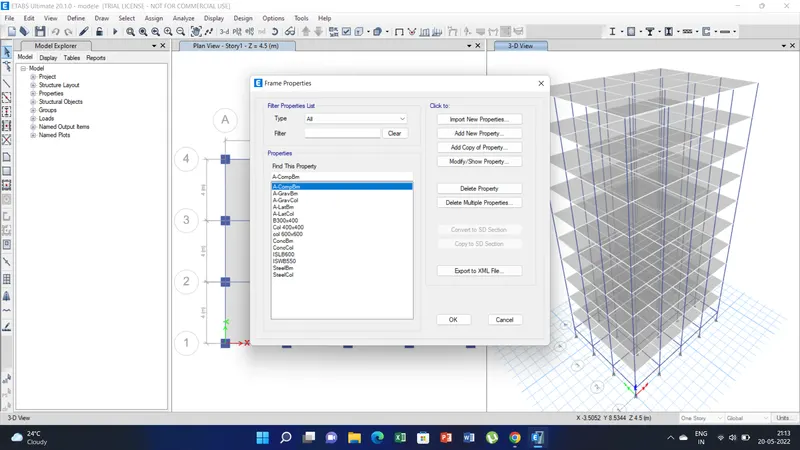
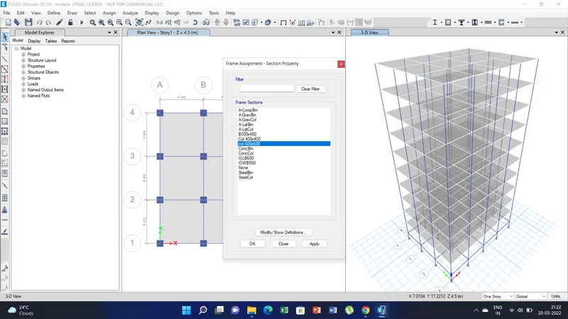
4) Now go to define tab-frame-frame section. Than Click on modify/show property. There make the previous column to 600 x 600mm.
5) Create another column by add new property option and make the column as 400x400mm.
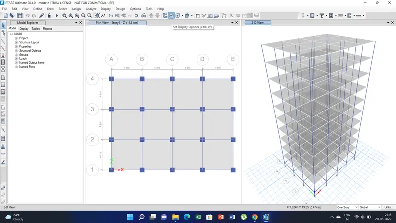
6) Now go to the set display option there untick the beam and floor option.
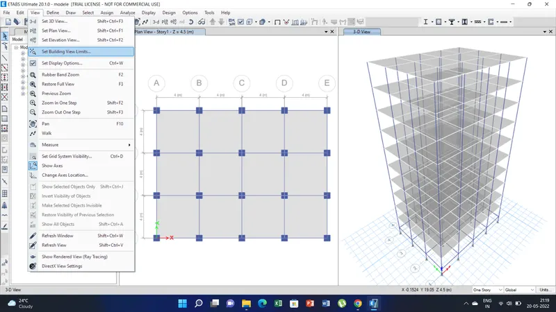
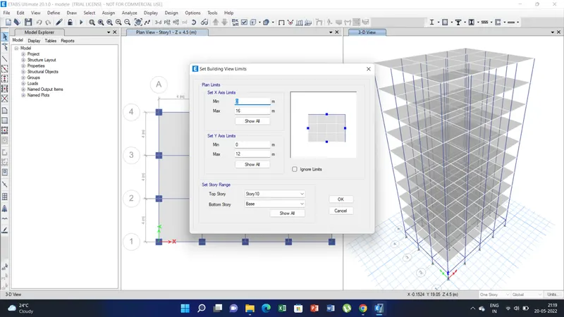
7) Now go to the view option tab and click on the set building view limits, than change the value from base to storey 5.
8) Select all the columns and assign the section property as column 600x600.
9) Similarly for column 400x400mm from storey 6 to storey 10 go to again view option tab and click on the set building view limits.
10) Change the value from storey 6 to storey 10. Than assign the frame properties as column 400x400mm as done in steps 8.
11) Now in the set display option tick the beam and floor option.
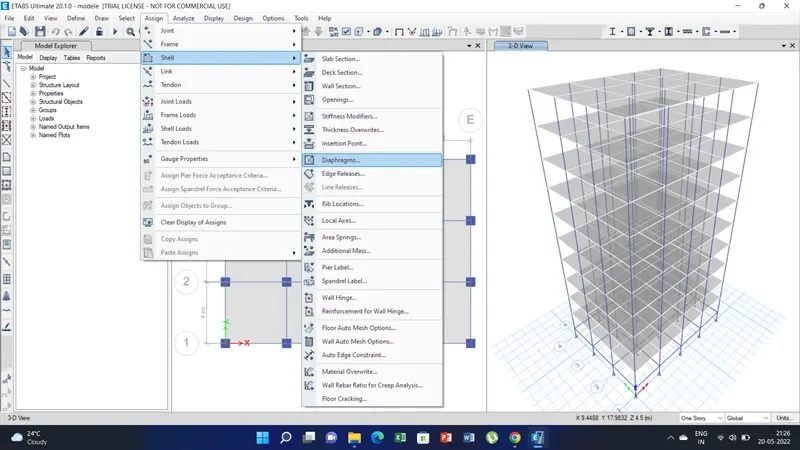
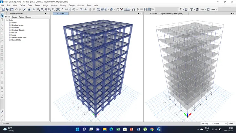
12) To assign the diaphragam select the slab from the select tab option and than assign shell-diaphragam and run the analysis.
Procedure: Model F
1) Here we have to make the columns 600x600 for all 10 storeys.
2)Save the mode E as Model F first from the save as type option.
3) Now again click on the set display options untick the beam and floor option.
4) select all the columns and assign the frame - property and than select the column 600x600mm.
5) All the columns will be assigned to 600x600mm. Now again tick the beam floor option from the set display option.
6) Select the slab from the select tab option and than assign the shell - diaphragam. And than run the analysis.
Procedure: Model G
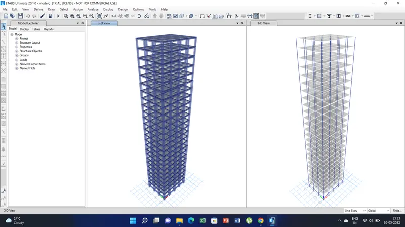
1) Here we have to create 25 no.s of storey and varying column sizes such as column 400x400 for upper 5 storeys, column 600x600 middle 10 storeys and column 800x800 for bottom 10 storeys.
2) Repeated the steps as done for model E.
Procedure: Model H
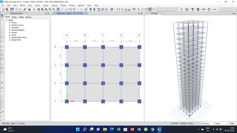
1) Here We have to make the column size to 800x800 for all the columns in model G.
2) Save the model G as Model H from the save as type option.
3) Repeat the steps as done for model F. Just here we have to change the column size to 800x800.
Procedure: Model J
1) Here we have to create imposed mass 10% larger than building H.
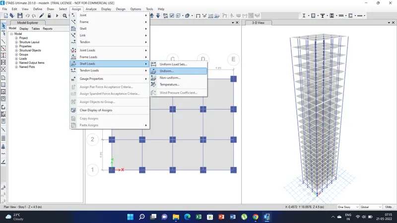
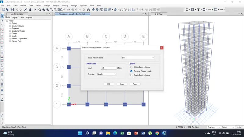
2) Select the slab and than Go to the assign tab- shell loads- uniform. Than select the live load and enter the value as 3.3kn/msq. i.e +10%.
3) Than save the file as Model J and run the analysis.
Procedure: Model K
1) Repeat the steps as done for Model J.
2) Here the load value has to be changed to 3.6kn/msq. i.e +20%
Comparision: Factors Influencing the natural period of a building.
| Criteria | Model | Analysis Result | Conclusion |
| Effective stiffness on Time Period | Model E | 1.73s | It can be concluded that higher the storey and varrying column sizes i.e reducing column sizes at top storeys it is more stable and time period is greater for higher storeys. |
| Model F | 1.73s | ||
| Effective stiffness on Time Period | Model G | 4.17s | |
| Model H | 4.4s | ||
| Effect of mass on Time Period | Model H | 4.41s | There is no differences in the time period as the load is uniformly distributed at all floors. Time period varies factor of 0.01s. |
| Model J | 4.42s | ||
| Model K | 4.43s | ||
| Effect of building height on time period | Model A | 0.5s | As the building height increases time period also increases i.e time period is directly proportional to the building height. |
| Model B | 1.03s | ||
| Model H | 1.73s | ||
| Model F | 4.41s | ||
| Effect of column Orientation on time period | Model B | 1.03s | For same column sizes defelction is same in both x & Y direction. But for varying column sizes the defelction will be higher in X direction for Model D than Model C. |
| Model C | 1.145s | ||
| Model D | 1.12s |
Comparision: Factors influencing mode shape of oscillation.
| Criteria | Model | Analysis Result | Conclusion |
| Flexural Stiffness of structural elements on mode shapes Model B | Flexural stifness of beam close to zero | 2.62s | It is almost double in time period if consider the flexural stiffness almost close to zero than regular. |
| Flexural stifness of beam close to regular | 1.03s | ||
| Effect of axial stiffness of vertical members on mode shapes Model H | Axial Cross Section for column is closed to zero | 5.99s | Making the axial cross section as 10% the time period increases by 1.5 secs. |
| Full axial cross section of columns regular | 4.41s | ||
| Effect of degree of fixity at column base Model B | Column Support Pinned | 1.03s | When the column support are fixed lesser the time period hence lesser deflected as compared to pinned. |
| Column support fixed | 0.941s |