Project 1_Comparative study of different storey buildings for Seismic forces
 aim – Factors influencing the Natural Period of a building
Structural Element Sizes
- Beams : 300 × 400 mm
- Columns : 400 × 400 mm
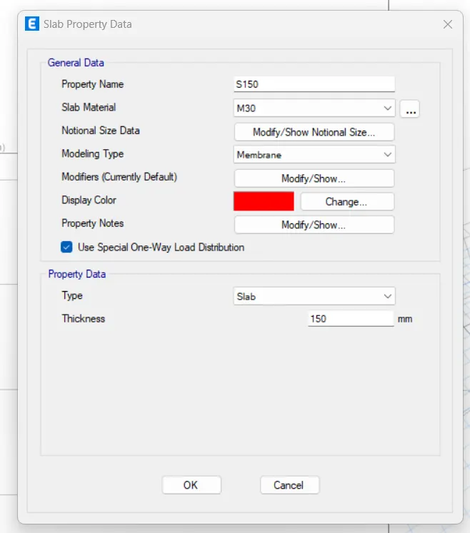
- Slab : 150 mm thick
Material Properties
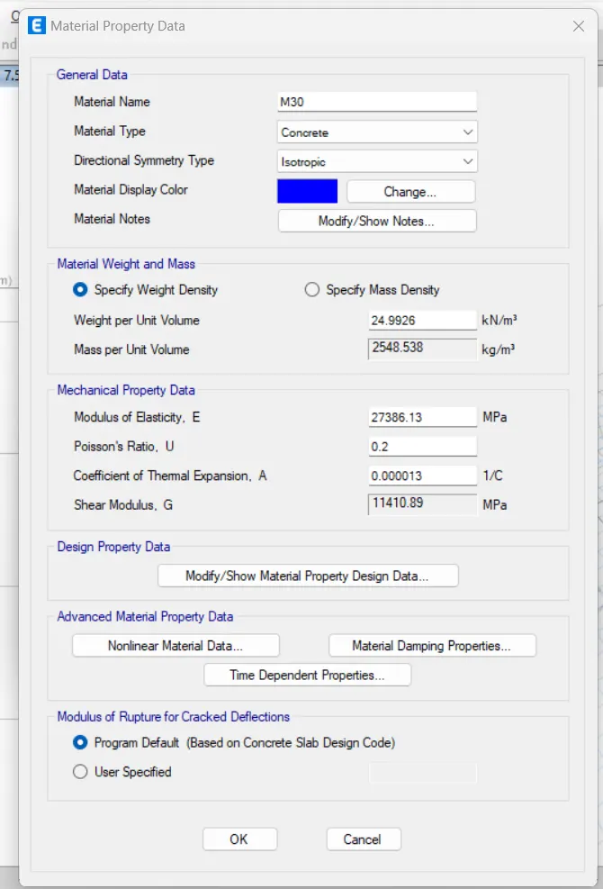
- Grade of Concrete : M30
- Grade of Steel Reinforcement Bars : Fe 415
Loading
- Dead Load on beams from infill wall : 10 kN/m
- Live load on floor : 3 kN/m2
(what is the seismic mass?)
Buildings are assumed to be pinned at base
INTRODUCTION : There are 10 project of different story building (A, B, C, D, E, F, G, H, J, K).
Factors influencing the dynamic characteristics of a building
Buildings oscillate during earthquake shaking. The oscillation causes inertia force to be induced in the building.
The intensity and duration of oscillation, and the amount of inertia force induced in a building depend on features of buildings, called their dynamic characteristics, in addition to the characteristics of the earthquake shaking (beyond the control of an engineer) itself.
The important dynamic characteristics of buildings are modes of oscillation and damping (assumed constant in most practical cases). A mode of oscillation of a building is defined by associated Natural Period and Deformed Shape in which it oscillates.
Every building has a number of natural frequencies (how many?), at which it offers minimum resistance to shaking induced by external effects (like earthquakes and wind) and internal effects (like motors fixed on it).
Each of these natural frequencies and the associated deformation shape of a building constitute a Natural Mode of Oscillation.
The mode of oscillation with the smallest natural frequency (and largest natural period) is called the Fundamental Mode; the associated natural period T1 is called the Fundamental Natural Period.
Regular buildings held at their base from translation in the three directions, have two fundamental translational natural periods, Tx1 and Ty1, associated with its horizontal translational oscillation along X and Y directions, respectively, and one fundamental rotational natural period Tθ1 associated with its rotation about an axis parallel to Z axis.
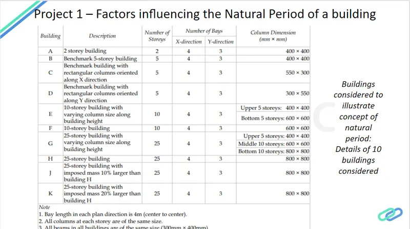
Effect of stiffness on T: Compare fundamental natural periods of buildings E & F as well as G & H. Why is there a marginal or significant difference in the fundamental natural periods?
Effect of mass on T: Compare fundamental natural periods of buildings H, J and K. Have the buildings become more flexible or stiff due to change in mass?
Effect of Building Height on T: How does the fundamental natural periods of Buildings A, B, F and H change with change in building height?
Effect of Column Orientation on T: How does the fundamental natural periods of Buildings B, C and D change with change in column orientation?
Factors influencing the Mode shape of oscillations
Mode shape of oscillation associated with a natural period of a building is the deformed shape of the building when shaken at the natural period. Hence, a building has as many mode shapes as the number of natural periods.
For a building, there are infinite numbers of natural period. But, in the mathematical modeling of building, usually the building is discretized into a number of elements. The junctions of these elements are called nodes. Each node is free to translate in all the three Cartesian directions and rotate about the three Cartesian axes. Hence, if the number of nodes of discretization is N, then there would be 6N modes of oscillation, and associated with these are 6N natural periods and mode shapes of oscillation.
Effect of Flexural Stiffness of Structural Elements on mode shapes: Compare fundamental mode shape of Building B in two situations when flexural stiffness of beams relative to that of adjoining columns is very small versus when it is large.
Effect of Axial Stiffness of Vertical Members on mode shapes: Compare fundamental mode shape of Building H in two situations when axial cross-sectional area of columns is very small versus when it is large.
Effect of Degree of Fixity at column bases on mode shape: Compare fundamental mode shape of Building B in two situations when base of columns is pinned versus when it is fixed.
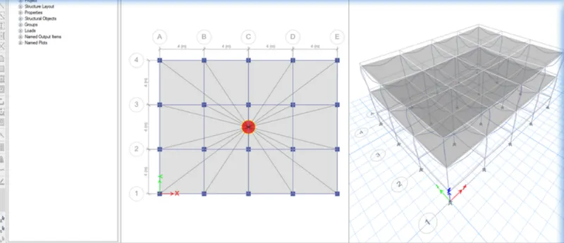
Building A
2 storey building
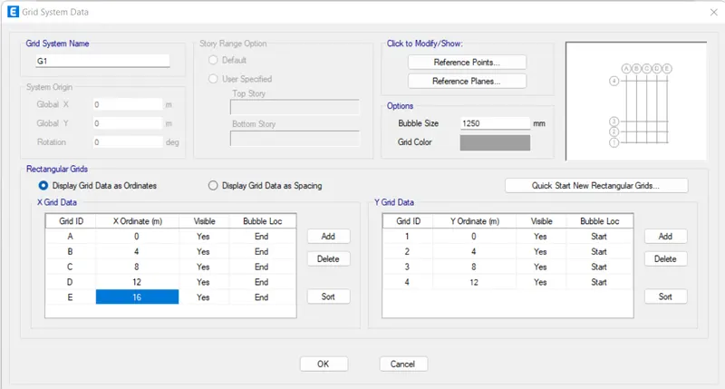
number of bay
X direction 4, Y direction 3
size of beam 400X400mm
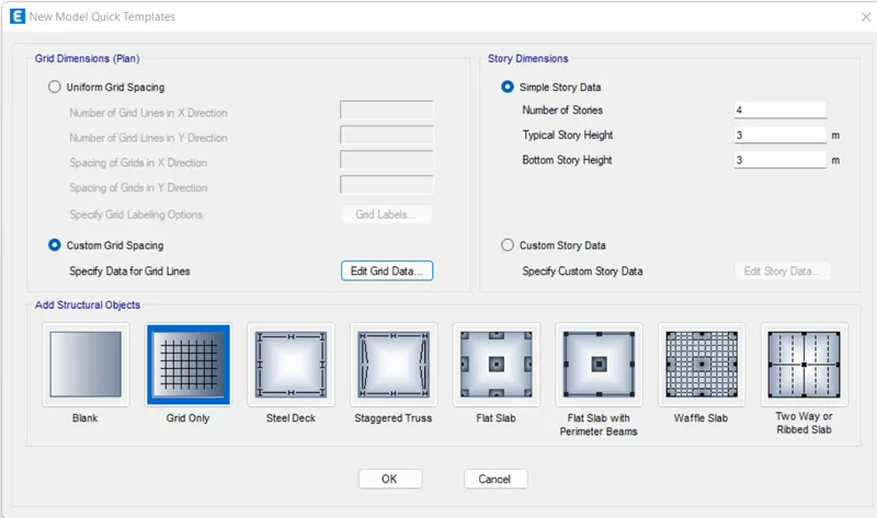
step 1) open the etabs software and go for new model
step 2
step3
first go to edit custom grid spacing
set no. of bay and spacing between two grids and press ok
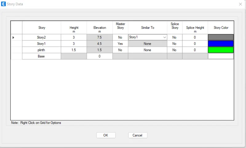
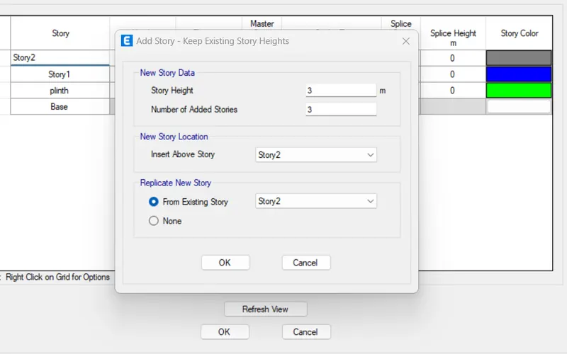
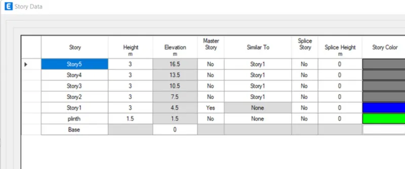
now storey data
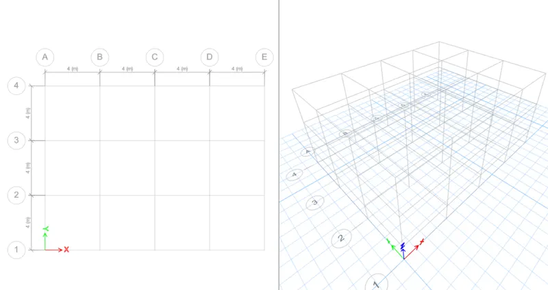
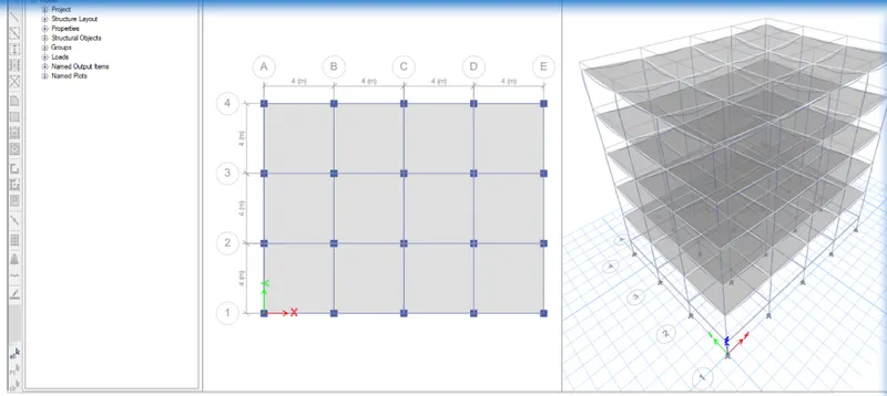
our building frame are created
step 4 go to material proprty from define
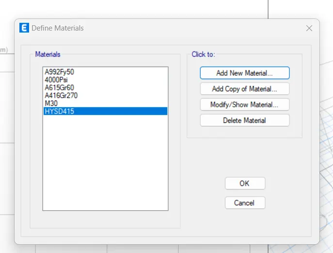
add new material of concrete M30 and steel fe 415
step 5) go for slab section
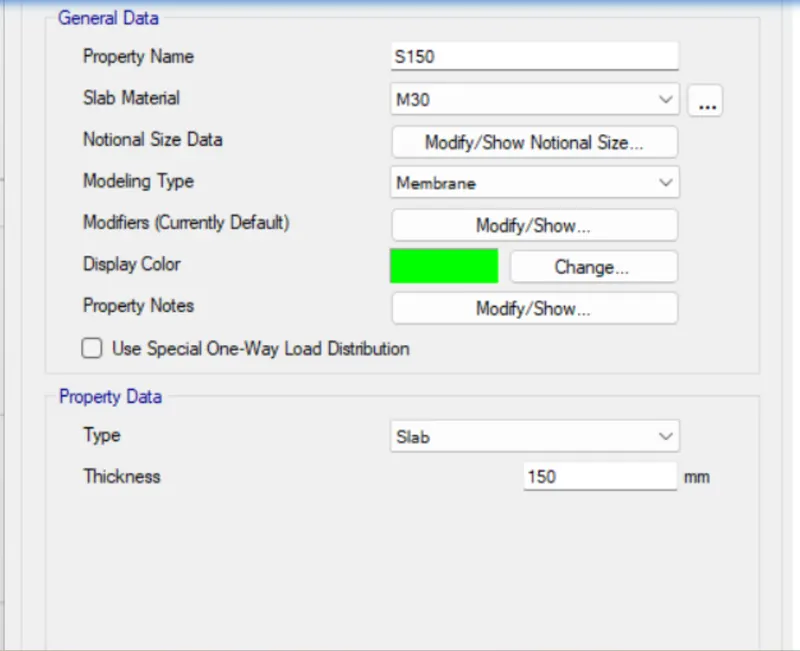
add 150mm thick membrane slab with M30 grade concrete
step 6) go for load patterns
click on load patterns option from define
now we add load for wall
and earthquake in X and Y respectively
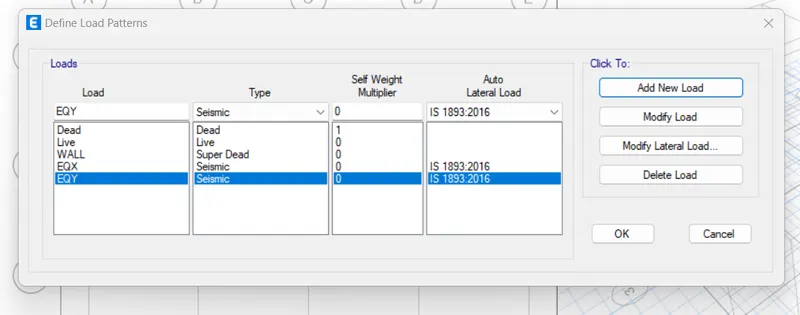
add 1 for dead load and wall
and 0.25 for live load
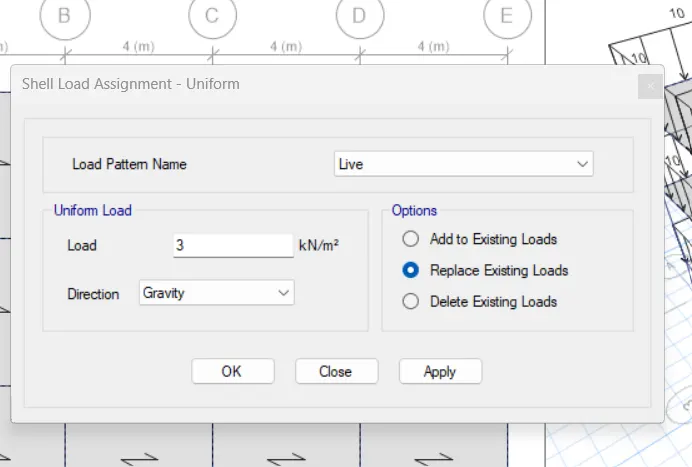
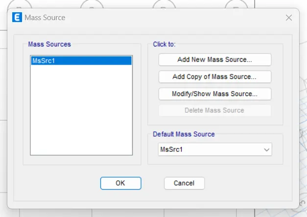
step 8) now go for load cases
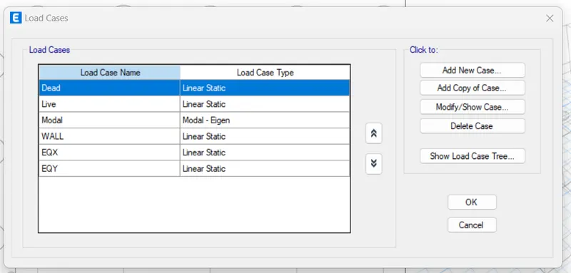
step 9) create load combination
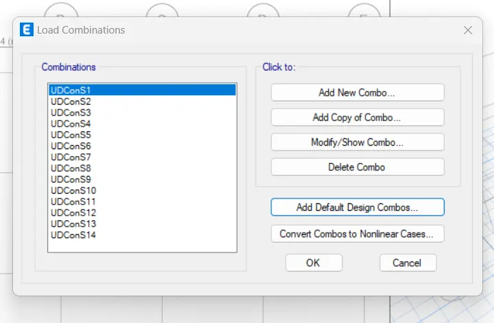
step 10) now go for column modelling
clickm on draw column option
change working plane as all stories

step 11) beam modelling
go to quick draw beam change working plane as all storey
and draw the beam to take a cursor between two grids
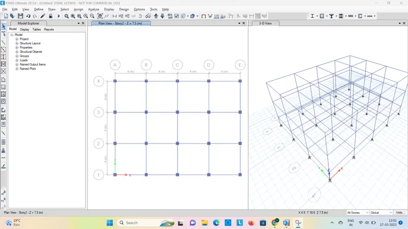
step 12) slab draw
go to quick draw slab
draw only for storey one and two
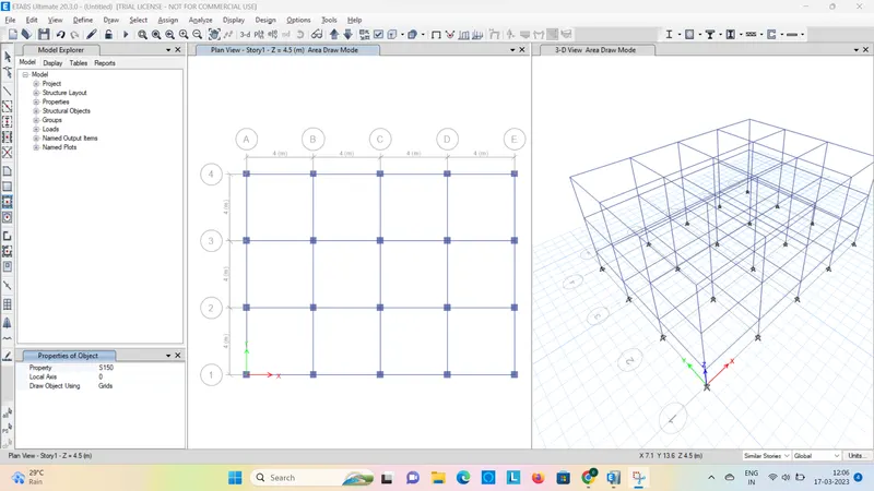
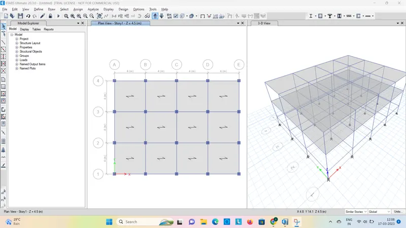
step 13) assign loads
select beam properties from beam
to select beams
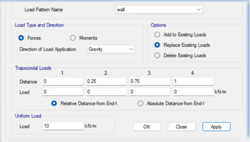
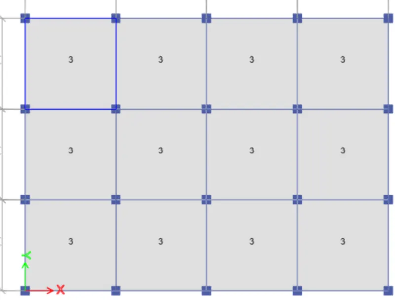
step 15) diaphragms property
select all the slabs from select option
and assign diaphragms
building b
Given,
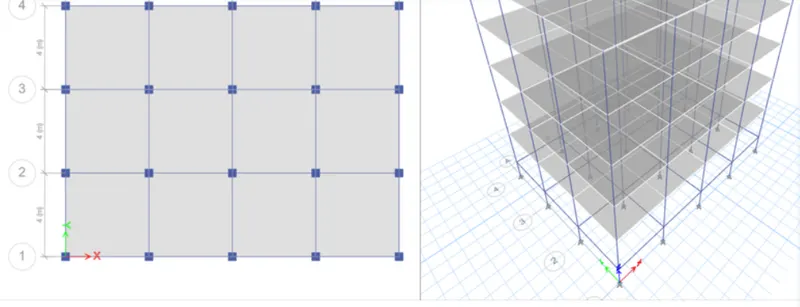
5 storey building
number of bay
X direction 4, Y direction 3
size of beam 400X400mm
step 1) open the etabs software and go for new model
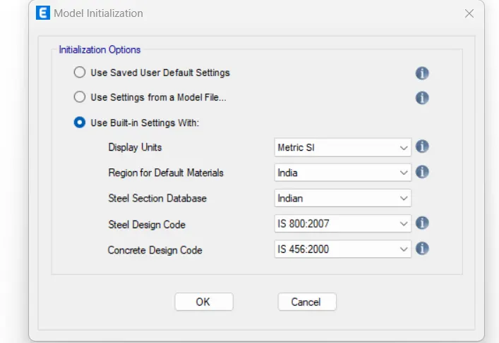
then set units and press ok in intialization optionn
set no. of bay and spacing between two grids and press ok
add new material of concrete M30 and steel fe 415
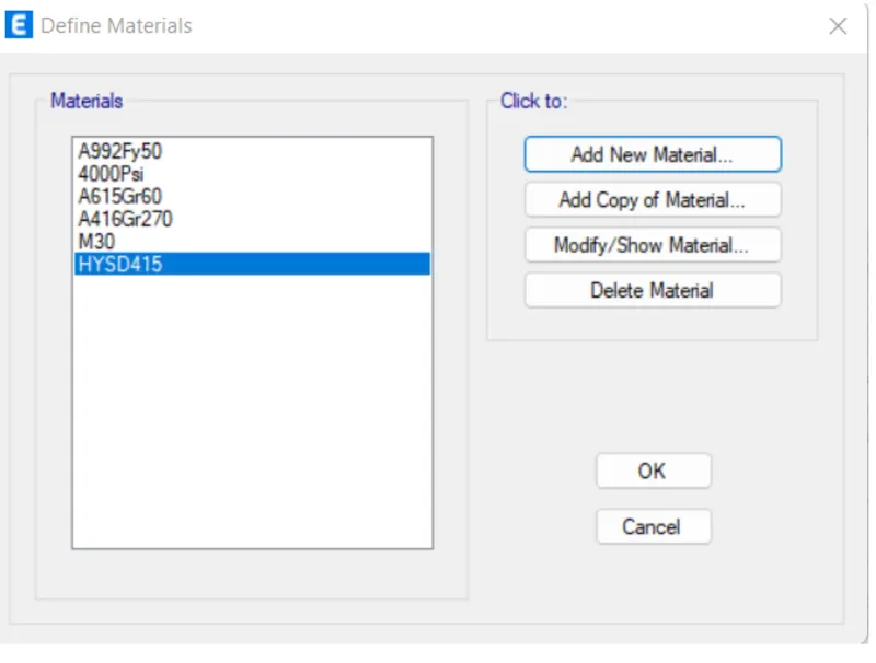
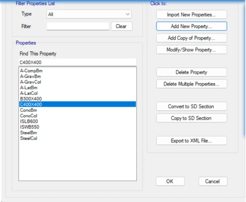
add column frame and beam section according to given size and material
add 150mm thick membrane slab with M30 grade concrete
click on load patterns option from define
now we add load for wall
and earthquake in X and Y respectively
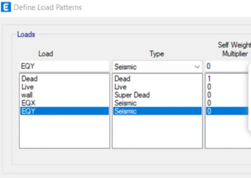
and 0.25 for live load
step 9) create load combination
clickm on draw column option
change working plane as all stories
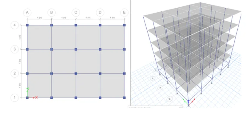
go to quick draw beam change working plane as all storey
and draw the beam to take a cursor between two grid
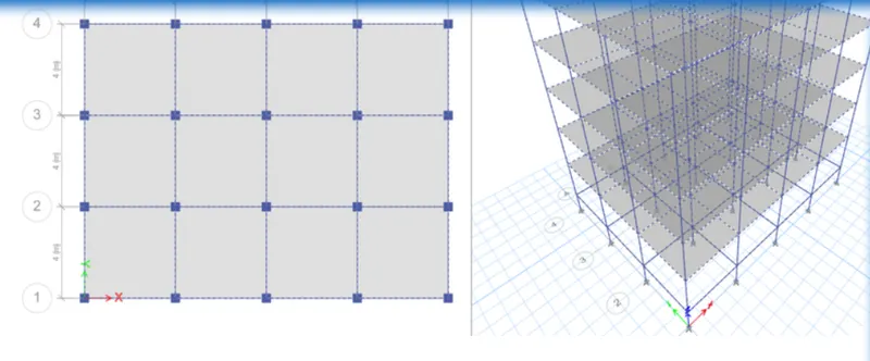
go to quick draw slab
draw only for storey one and two
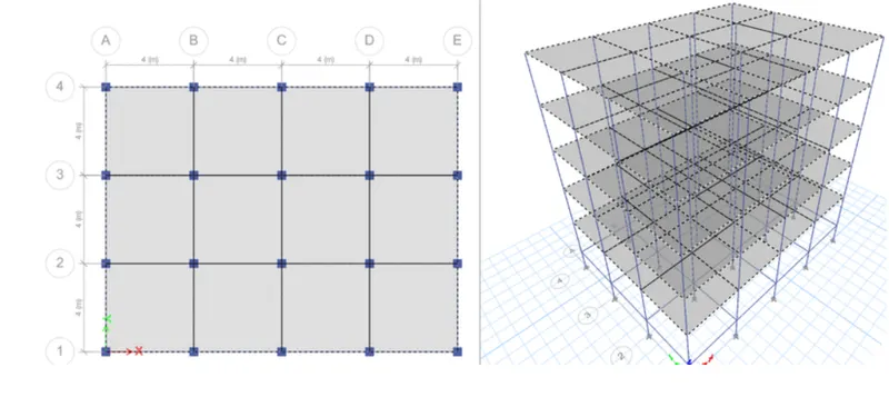
select beam properties from beam
to select beams
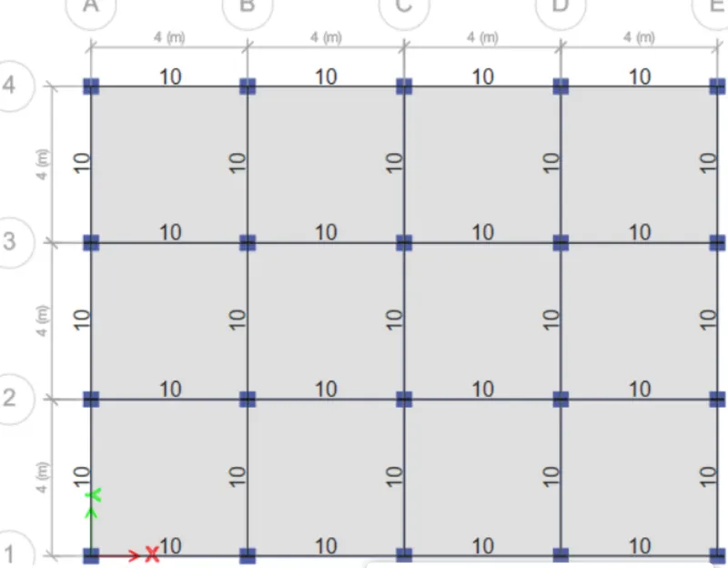
select all the slabs from select option
and assign diaphragms
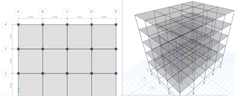
step 16) run analysis
Building C
Given,
5 storey building
number of bay
X direction 4, Y direction 3
size of beam 550X300mm
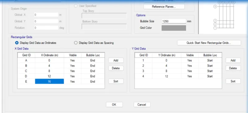
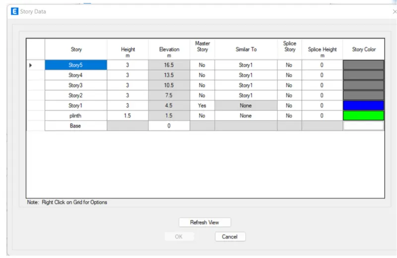
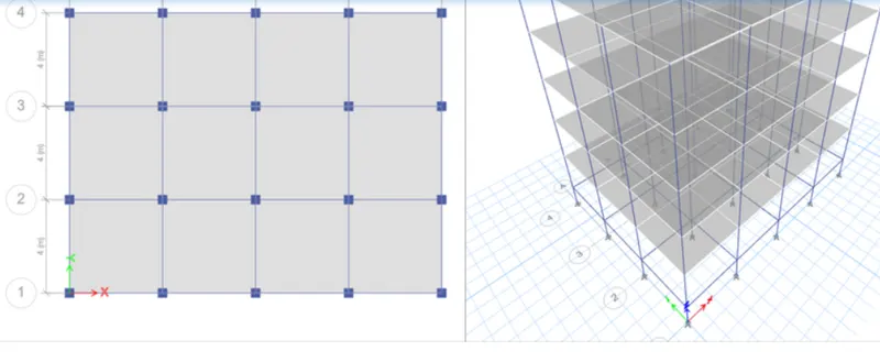
step 3) go to material proprty from define
add new material of concrete M30 and steel fe 415
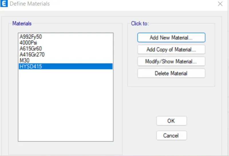
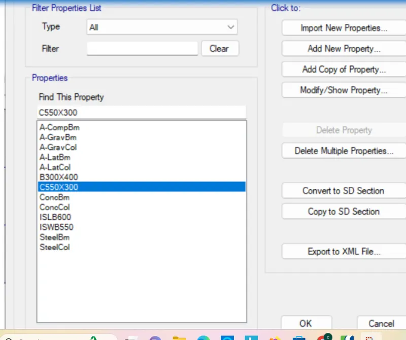
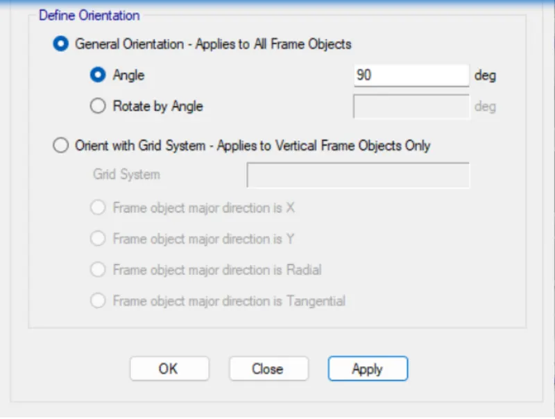
by giving 90degree rotation
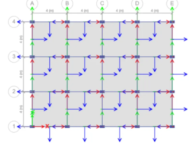
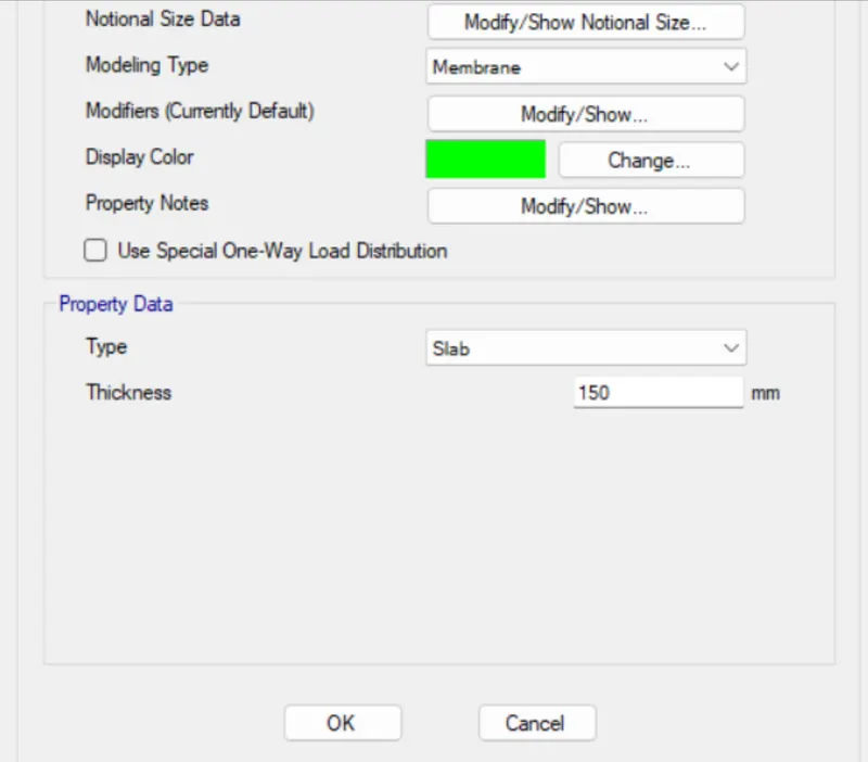
add 150mm thick membrane slab with M30
click on load patterns option from define
now we add load for wall
and earthquake in X and Y respectively
clickm on draw column option
change working plane as all stories
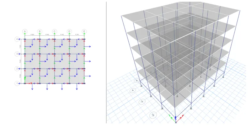
go to quick draw beam change working plane as all storey
and draw the beam to take a cursor betweenline to line
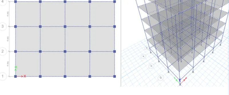
step 12) slab draw
go to quick draw slab
draw only for storey one and two
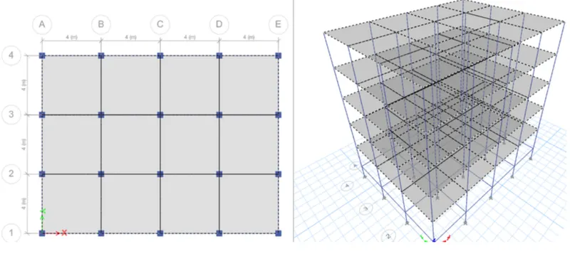
select beam properties from beam
to select beams
select all the slabs from select option
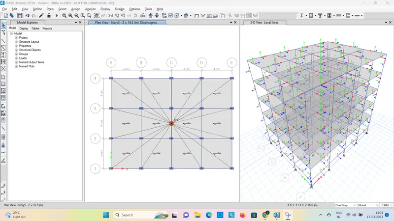
after complition of modelling part run the analysis
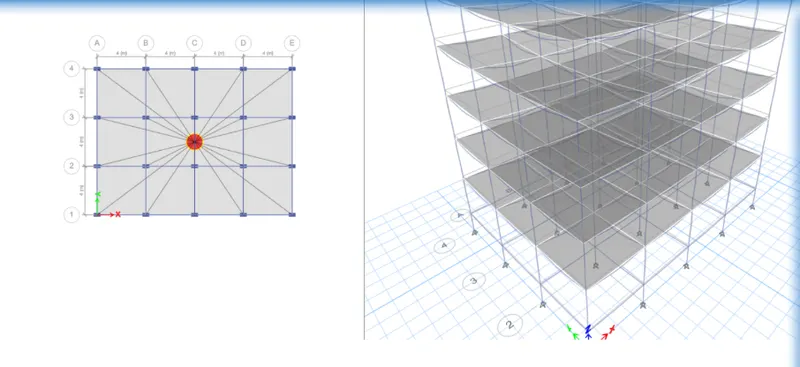
Given,
5 storey building
number of bay
X direction 4, Y direction 3
size of beam 300X550mm
oriented along y direction
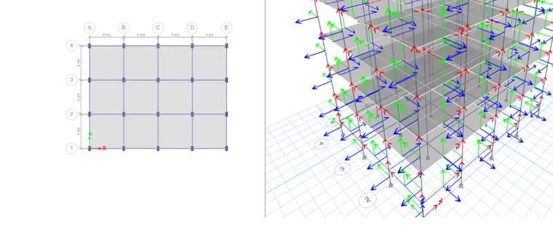
step 1) open the etabs software and go for new modelthen set units and press ok in intialization option
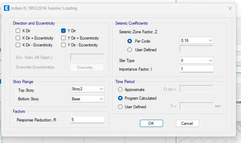
set no. of bay and spacing between two grids and press ok
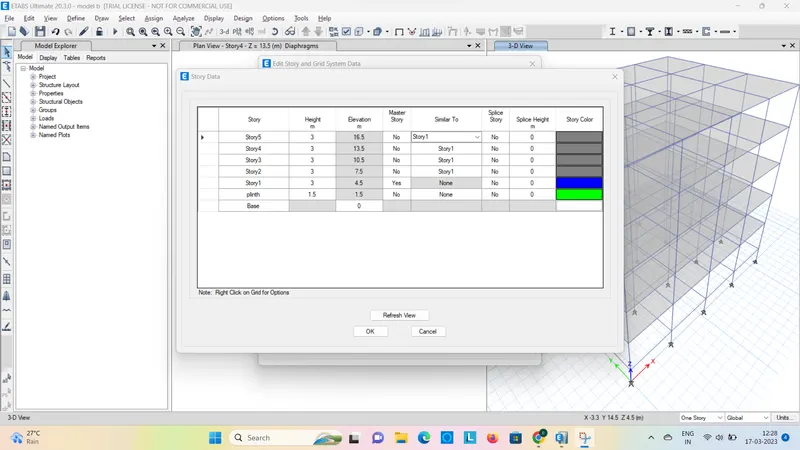
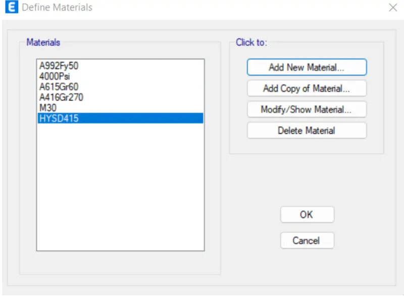
add new material of concrete M30 and steel fe 415
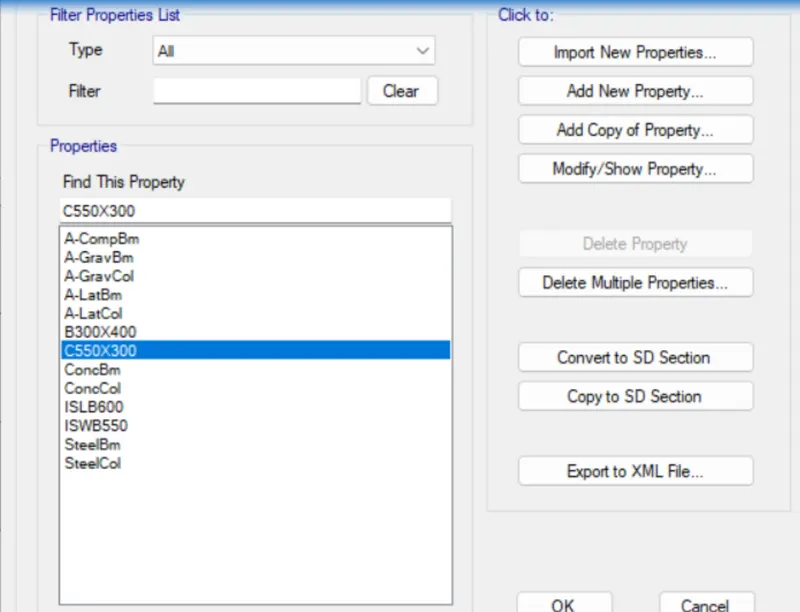
add column frame and beam section according to given size and material
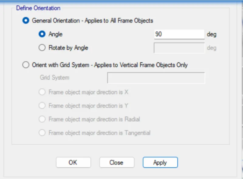
assign the loacal axis at X direction
by giving 90degree rotation
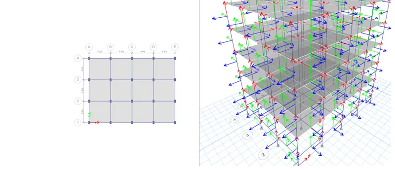
click on load patterns option from define
now we add load for wall
and earthquake in X and Y respectively
clickm on draw column option
change working plane as all stories
go to quick draw beam change working plane as all storey
and draw the beam to take a cursor between two grids
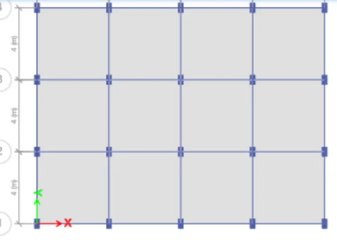
step 12) slab draw
go to quick draw slab
draw only for storey one and two
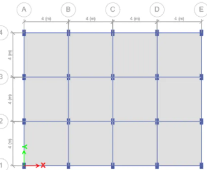
select beam properties from beam
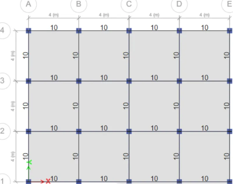
select all the slabs from select option
and assign diaphragms
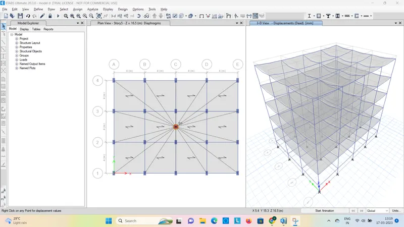
BUILDING E (G+ 10 )
Column sizes :
for top 5 storeys: C 400X400
Column sizes
for bottom 5 storeys: C600X600
PROCEDURE :
In this model, we need to add up 5 more storeys to our model.
In addition, we also need to assign different column sizes on different floors.
we'll first save the ETABS file for building D as a new model for building E.
Then, edit the story data as we have done for our previous models in ETABS.
Then, we need to add two new column sections with the required directions and assigment
STEP 1
Add 5 more story in previous structure
so that go to the Edit option
click on Edit Story And Grid System
one dialogbox is open
from that click on Modify Story Data option
add 5 story there shown below
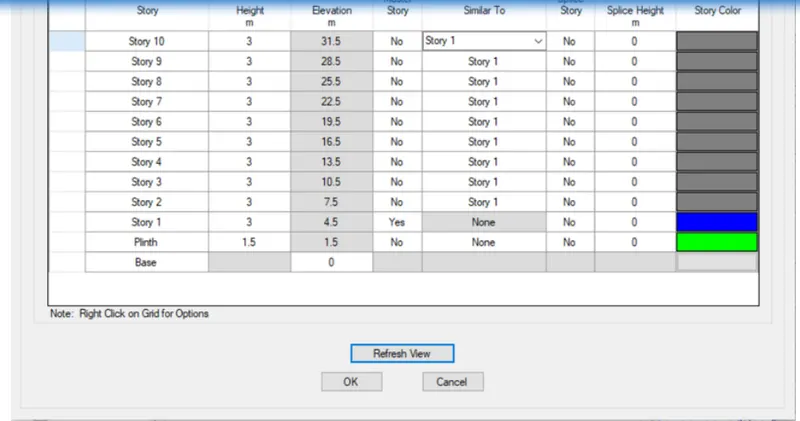
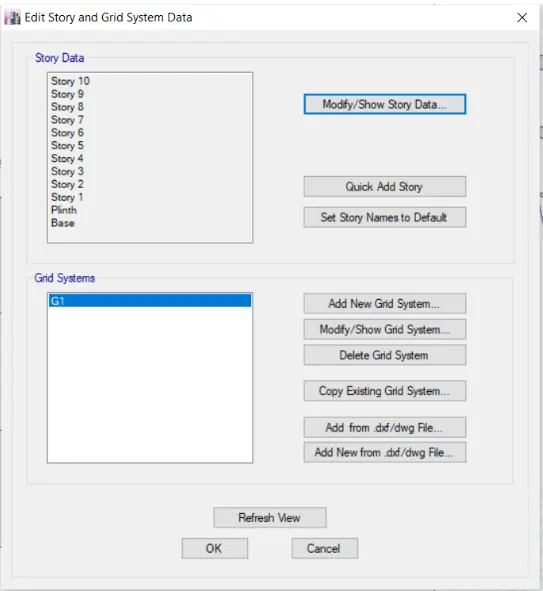
STEP 2
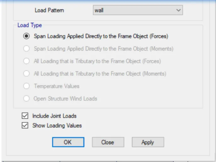
Check the wall load and floor load of the structure
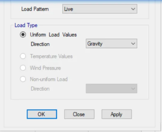
click on Display shell load assign
select the load pattern as live load
 \
\
Change the column size as 600x600
so that click on Define tab
then Section properties
then Frame section
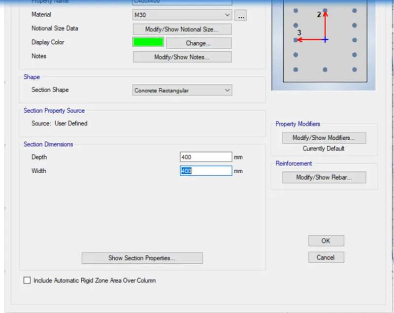
select the c550x300
then click on Modify section
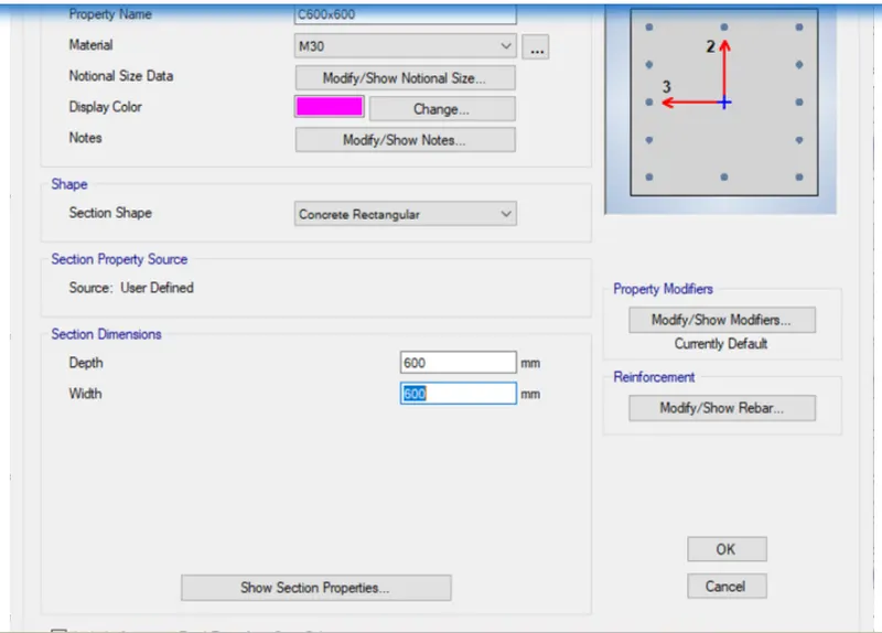
one dialogbox is open shown below
give the property name as c600x600
give the depth as 600
and width as 600
Then Add one more new column size 400 by 400
so that click on Add new proprties
give the name as c400x400
then width of column as 400
STEP 4
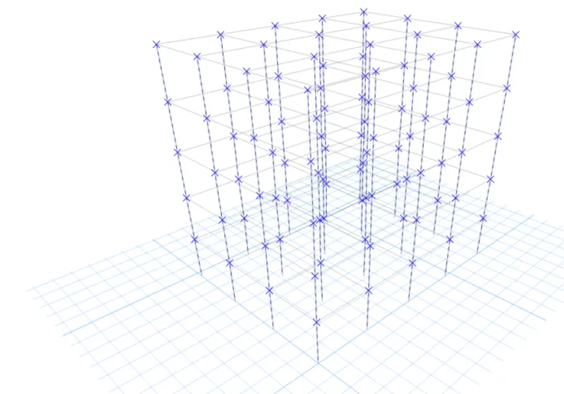
Select the column only
for that hide the beam and floor
click on set view point tab
and unselect the beam and floor and then click ok
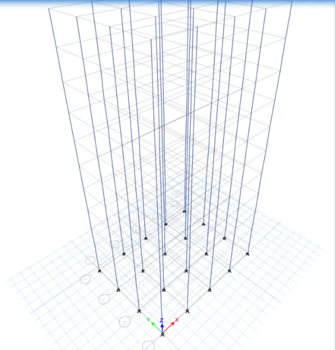
Select the column from floor 6 to 10
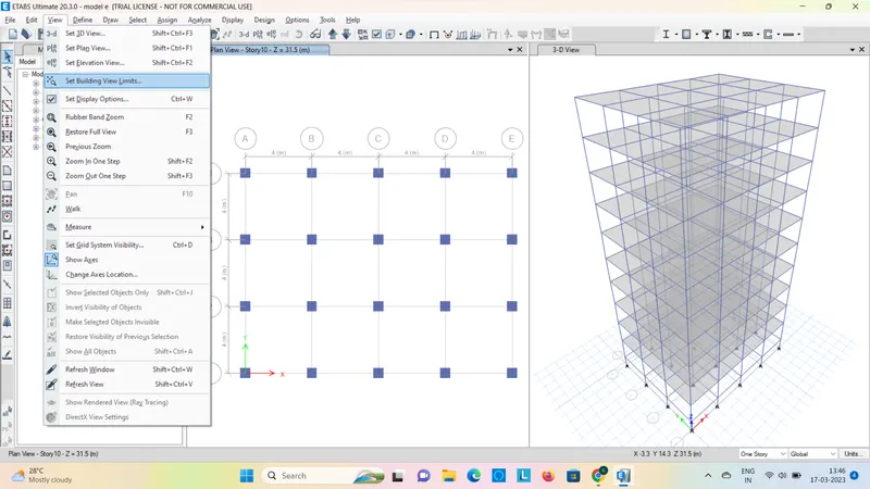
so that , click on view tab
Then click on Set Building view Limits
one dialogbox is open
from that select the Top story as Story 10
and base story as story 6
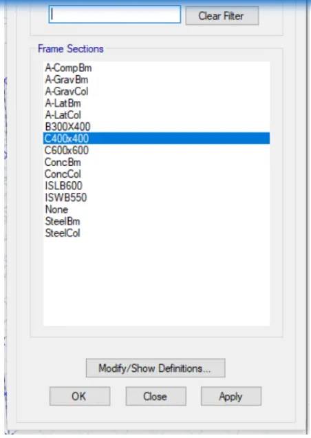
then click on Assign tab
then click on Frame and then click on Section Properties
3D VIEw
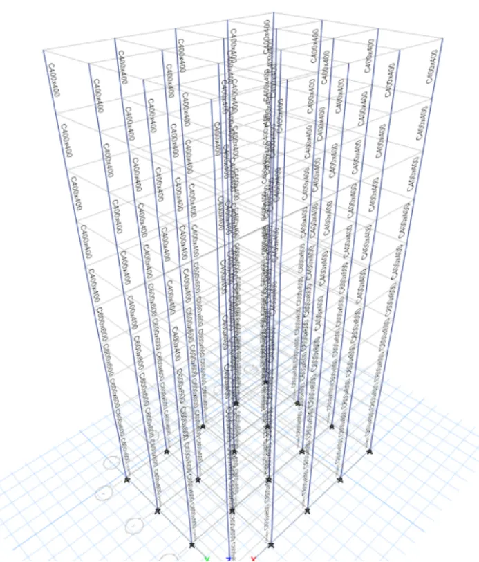
so that select the slab first
go to the select option
then click on properties and slab section
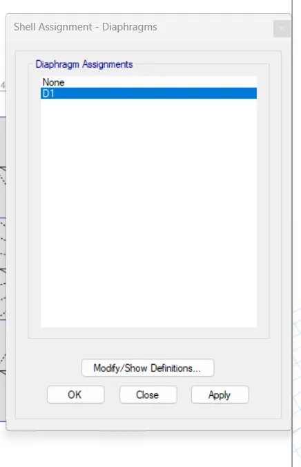
click on Apply and then OK
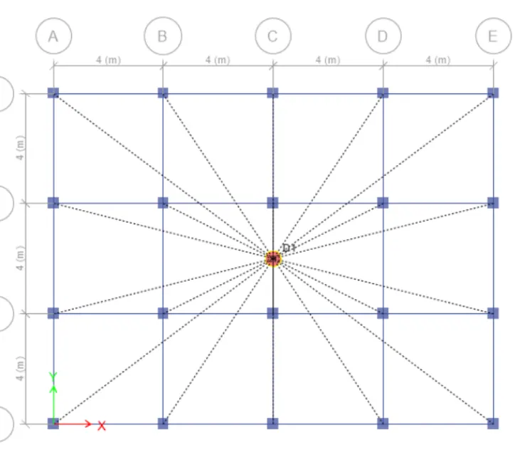
RuN ANALYSIS
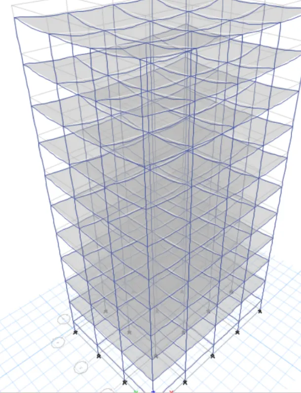
Columns for top 5 stories: C400X400
Columns for middle 10 stories: C600x600
Columns for bottom 10 stories: C800x800
PROCEDURE :
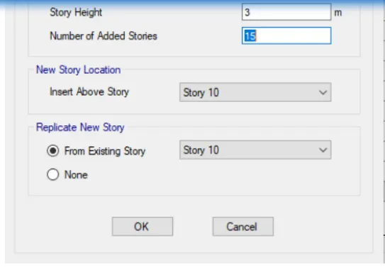
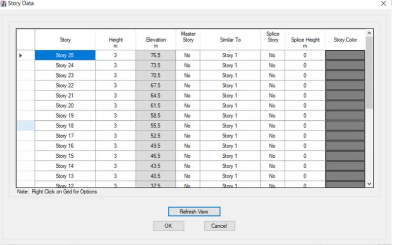
we need to add 15 new stories and assign different column sizes on different floors.
We can follow the exact procedure that has already been explained for the previous projec
to create this model by editing building F. The same
STEP 1
Click on File manu
then click on Save As then give the fine name as BUILDING G
STEP 2
Add more 15 story in previous story
so that click on Edit
then click on Edit Story And Grid System Data option
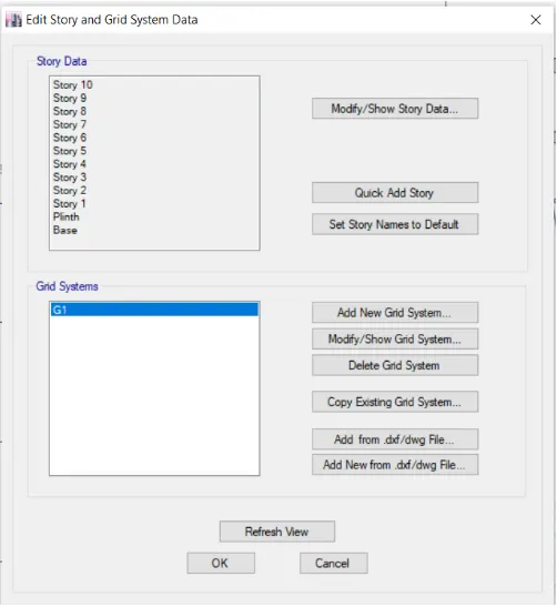
again one dialogbox is open
from that add more 15 story
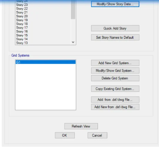
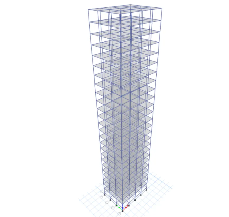
check the live load and wall loads of the structure
Check Live load :
click on Display Shell Load Assign
one dialogbox is open
select the load pattern as Live load
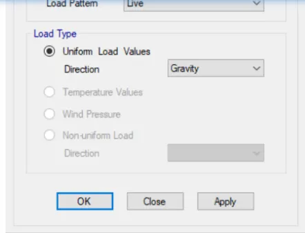
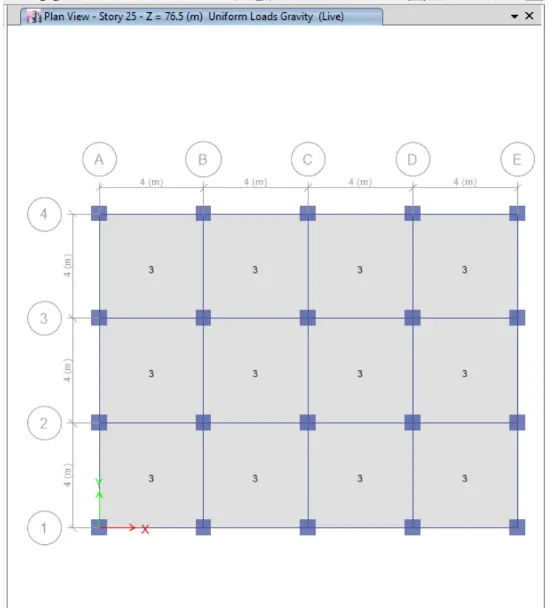
so that click on Display Frame Load Assign tab
one dialogbox is open
select the load pattern as wall load
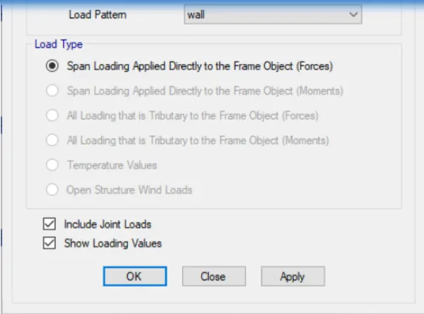
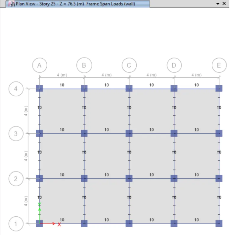
click on Appy and then OK
STEP 4
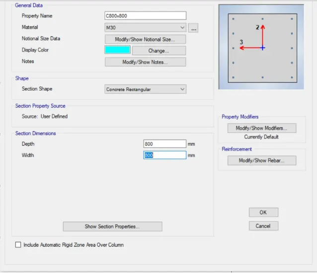
define columns
c400x400
c600600
one dialogbox is open
create a new column
c800x800
STEP 5
Apply different size of columns for each story
so that click first hide the beams and floors of the structure .
click on Set Display View tab
unselect the beam and floors option
click on Apply and then OK .
STEP 6
Click on assign tab
then click on Frame and then Section Properties
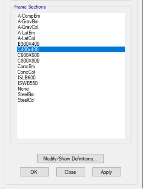
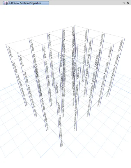
again click on View option
then click on Set Building Limets option
one dialogbox is open
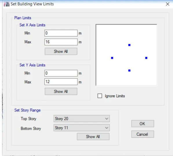
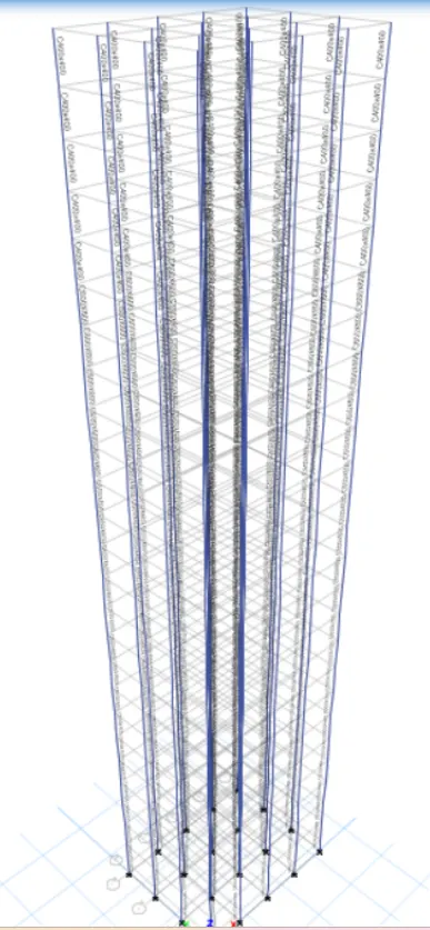
click on Set Display Views Option
and select the Beam and Slab Option
and then click on OK.
STEP 7
CHECK for diaphragms
first select the slab
click on Select tab
then again click on Select and then properties , next is slab section
one dialogbox is open
from that click on Slab150
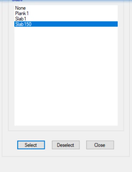
click on Assign tab
the click on Shell and then Diaphragms
one new dialogbox is open
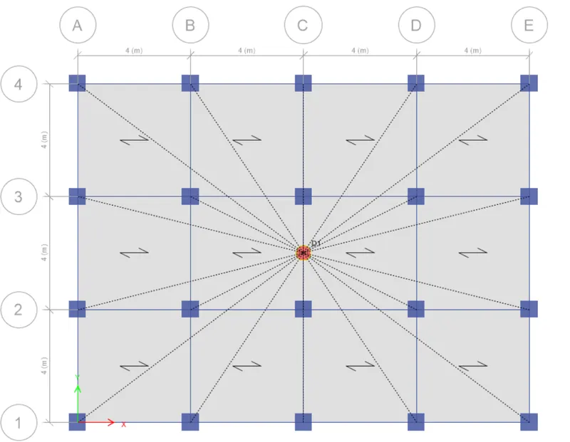
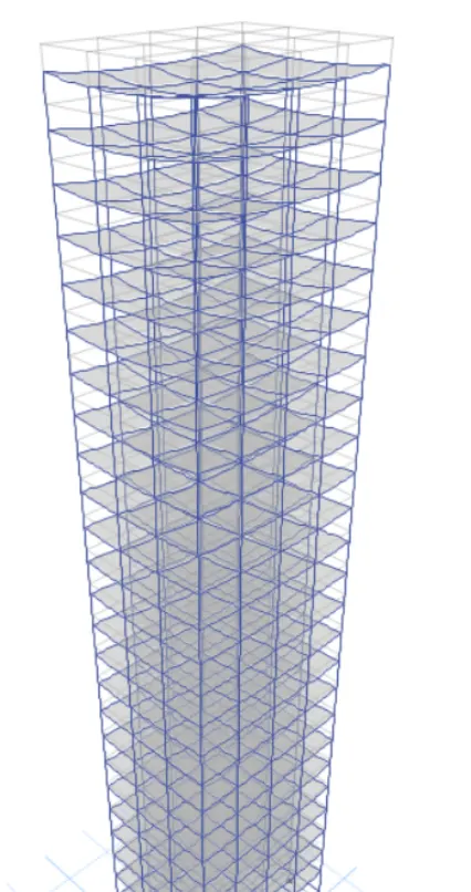
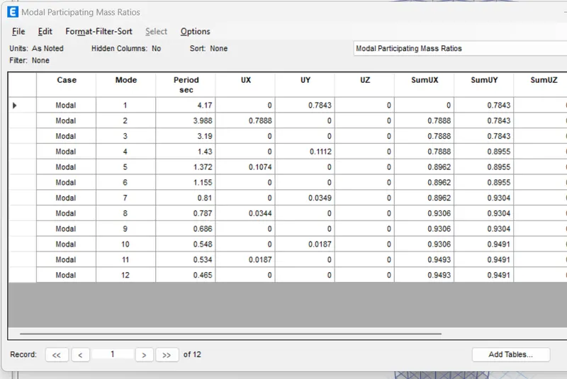
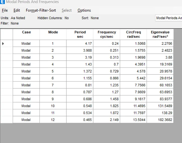
All column size is 800x800
PROCEDURE :
First click on File option
then click on Save as
Give the file name as BUILDING H
and the save it
STEP 2
First hide the Beam and floor
and the click on APPLY and the OK
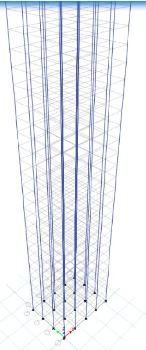
Assign all columns as 800x800
so that first select the columns
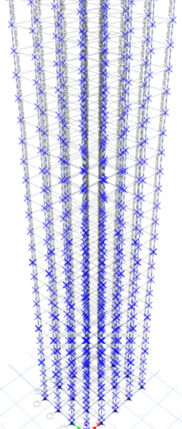
then click on Frame and then section properties
one dialogbox is open
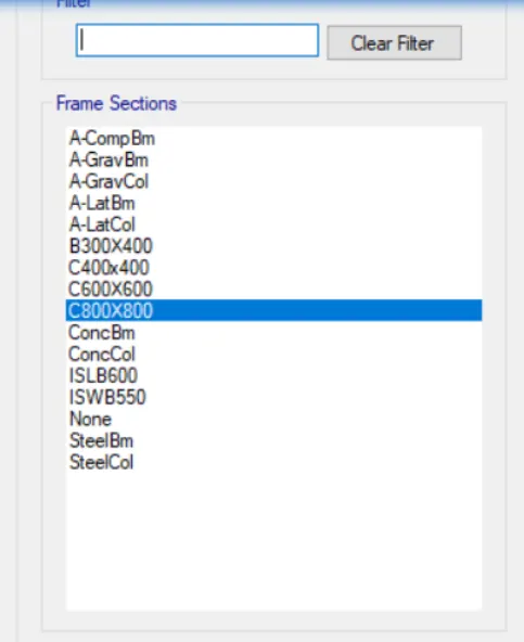
From that click on c800x800
STEP 4
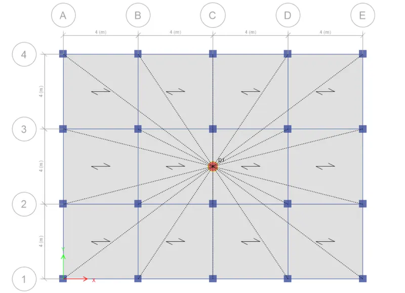
Select the beam and slab
so that click on set display option
then select the beam , floor and diaphragms option
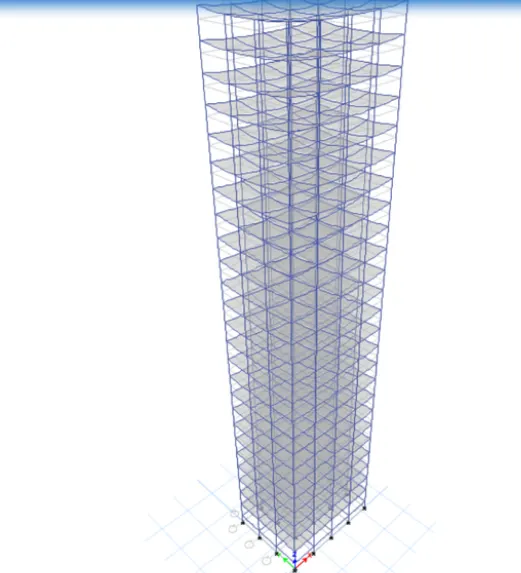
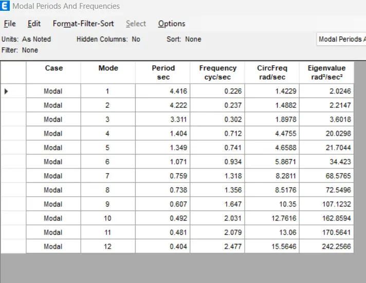
IN THIS CASE INCREATSE THE 10 % IMPOSED LOAD MEANS LIVE LOAD
PROCEDURE :
STEP 1
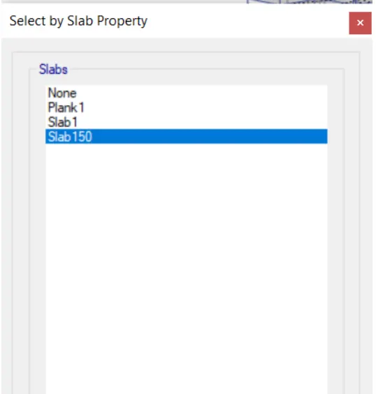
Select the all the slab
click on Select tab
STEP 2
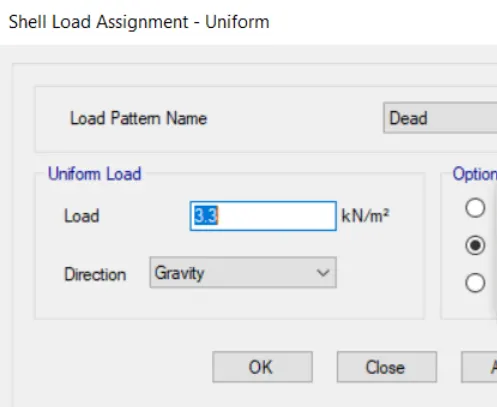
Increase the 10 % of live load
so that click on Assign tab
then shell load
then click on Unifom
one dialogbox is open
give the load as 3.3
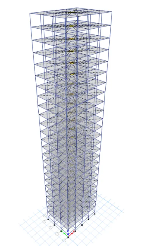
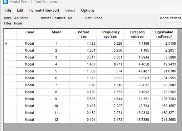
In this case the increase the mass of the building by 20 persent imposed load means live
load .
PROCEDURE :
STEP 1
Click on File tab
then click on Save as give the file name as BUILDING K
And then save it .
STEP 2
Increase the live load by 20 persent
click on Select tab
then again click on Select and then properties andthen slab section .
one dialogbox is open
select the Slab150

Assign load
so that click on Assign tab
then click on Shell load
then click on Uniform
one new dialogbox is open
from that select the load pattern as live load
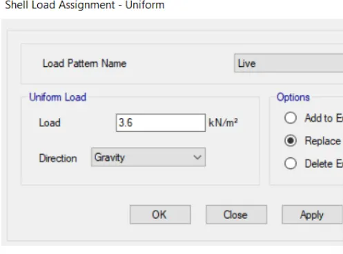
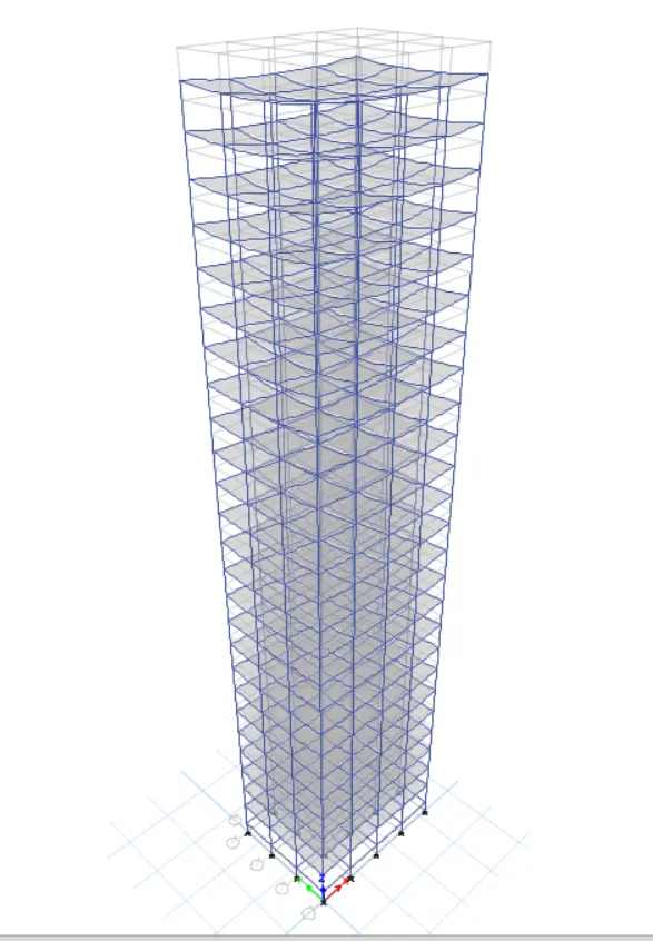
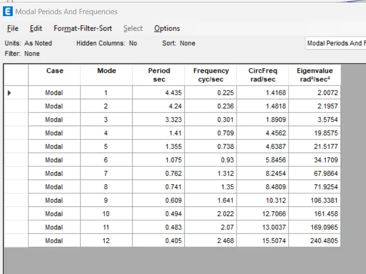
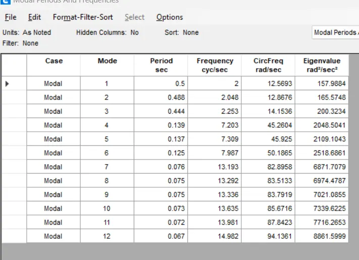
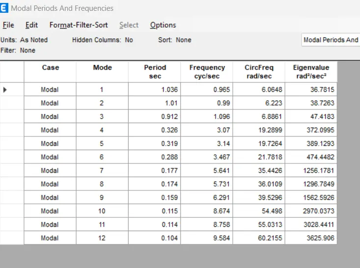
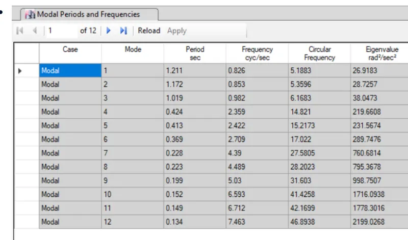
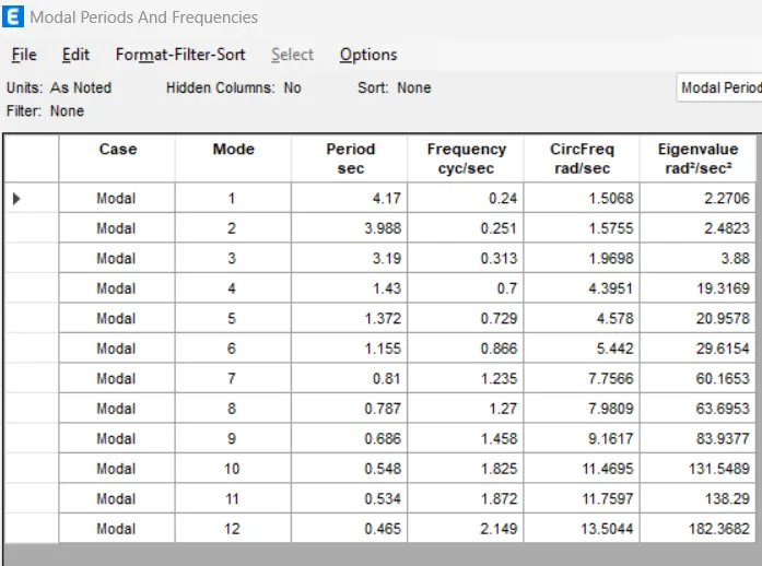
A] Effect of stiffness on T: Compare fundamental nature periods of building E&F as well as G
& H.
Why id there a marginal or significant difference in the fundamental natural periods?
Model
Type
No of
Stories
Column
configuration Results Conclusion
Building
E 10
Upper 5 stories =
400x400 mm
Bottom 5 Stories =
600x600 mm
As we could see that by changing the column
the buildings become more flexible or stiff due to change in mass
Model
Type
No of
stories
Percentage increase
in Load (Mass) Result Conclusion
Building
H 25 Load is taken as
3KN/m2
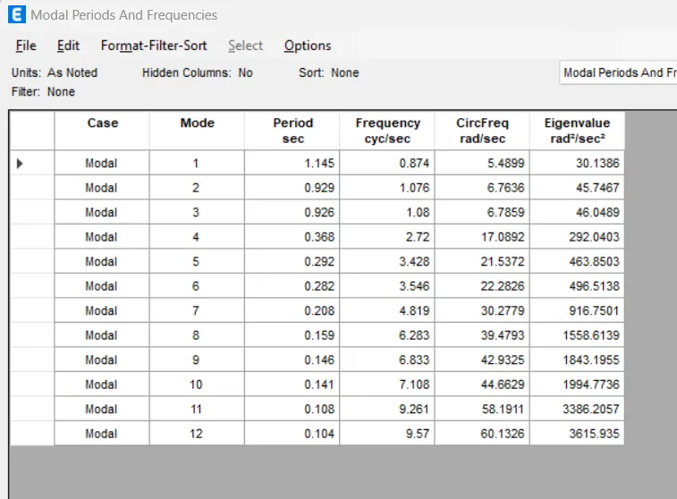
As we could see that time period is
increase as we increase the load or mass
Building J 25 Load Increase by 10%
(3.3kn/m2)
Therefore time period is directly
proportional to the mass of the building
Building
K 25 Load Increase by 20%
(3.6kn/m2)
C] Effect of building Height on T: How does the fundamental natural periods of Buildings
A,B,F and H change with change in building height?
Model
Type
No of
stories
Height of
Building Results Conclusion
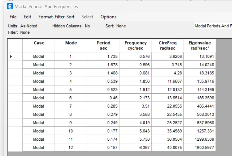
Building 2 7.5 m As we could see that the height of the building
increases the natural time period is also increaseBuilding F 10 31.5 m
Building H 25 46.5 m
D] Effect of column orientation on T: How does the fundamental natural periods of building
B, C and D change with change in column orientation?
Model
Type
No of
dtories
Column
orientation Results Conclusion
fundamental mode
Type
No of
stories
Flexural
stiffness of
beam
Results Conclusion
Building
B 5
100% If you decrease the flexural stiffness of beams,the
overall flexural strenght of the beam is also going to
reduce which increase the Natural period of time10%
F] Effect of Axial Stiffness of vertical Members on mode shapes: Compare the fundamenta
mode shape of building H in two situations when the axial cross-sectional area of columns
is very small versus when it is large.
Model
Type
No of
stories
Axial Stiffness
of Columns Results Conclusion
Building
H 25
100% As we axial stiffness of columns decrease, the
fundamental natural period of the building
increases regardless of its structural geometry
mode shape of Building B in two dituations when the base of columns is pinned versus
when it is fixed.
Model
Type
No of
stories
Base
support Result Conclusion
Building
B 5
Pinned
As we can see that in pinned support natural time
period is more as compared to fixed support.
Therefore fixed support will provide more resistance
as compared to pinned support