Project 1_Comparative study of different storey buildings for Seismic forces
1) Factors influencing the dynamic characteristics of a building
- Inertia force in the building is induced due to oscillation of the building which caused by earthquake shaking.
- The intensity and duration of oscillation, and the amount of inertia force induced in a building depend on features of buildings, called their dynamic characteristics.
- Modes and damping are the important dynamic characteristics of the building.
- Every building has a number of natural frequencies (Number of modes X 6 DOF for 3D model), at which it offers minimum resistance to shaking induced by external effects (like earthquakes and wind) and internal effects (like motors fixed on it).
- Natural mode of Oscillation is caused by these natural frequencies and the associated deformation shape of the building.
- The mode of oscillation with the smallest natural frequency and largest natural period is called the Fundamental Mode and the associated natural period T1 is called the Fundamental Natural Period.
- Regular building which is held at base experiences 3 direction translation and they are 2 lateral translation in X and Y direction and 1 is torsional translation on an axis parallel to Y direction.
2) Aim: To list out the factors influencing natural period of the building and the factors influencing the mode shape of oscillations.
Introduction : In this task a model of various design will be modelled as per the model described in Fig A and run analysis to achieve the result shown in fig B and Fig C. Fig D provides some of the details to be applied in the following structures.
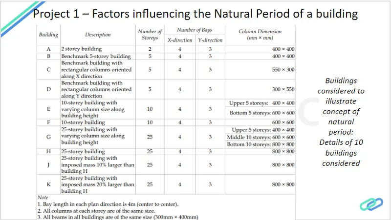
Fig A: Various model to be designed and analysed.
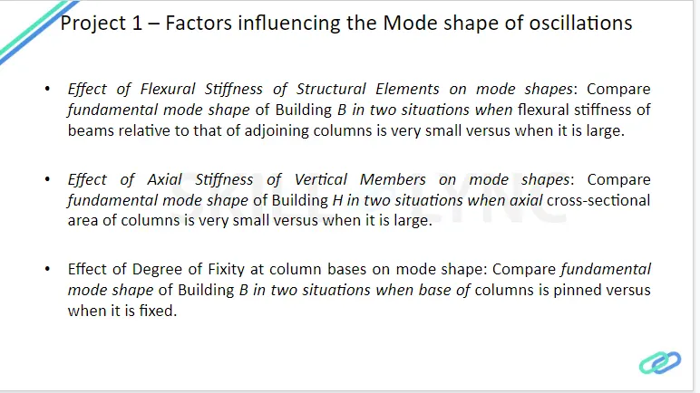
Fig B: Mode shape of oscillations results to be achieved.
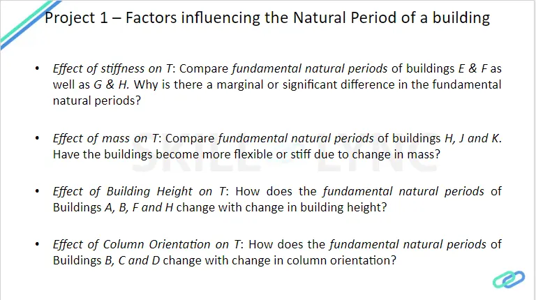
Fig C: Natural period of a building results to achieve.
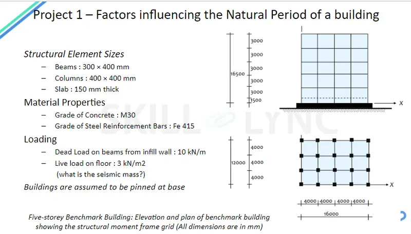
Fig D: Details to be defined when required.
Procedure:
To create and analyse building A
- Here the structure will be created in a similarly manner as discussed in challenge 6. The following Fig E will show the building A model created in ETabs.
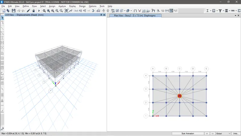
Fig E: Model A.
- Now building B will be creating by copying the Model A file and saving it as Model B file and editing the model A structure to Model B. Here the elements defined in this model is similar to Model A only additional is that we will be adding 3 more storey in model B. To do so, we will have to go to Edit tab > Edit stories and grid system as shown in fig F.
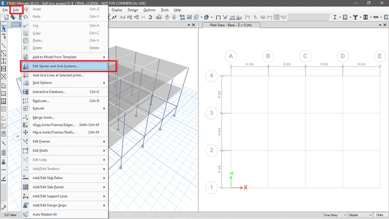
Fig F: Edit stories and grid system
- Click on Modify/show story data as shown in fig G.
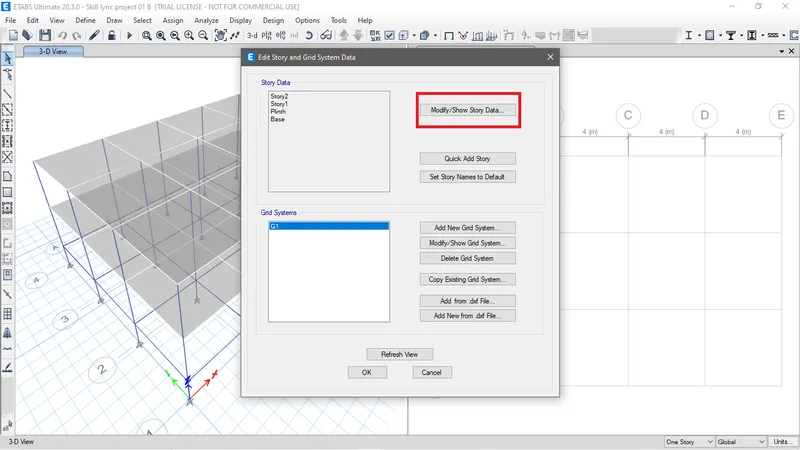
Fig G: Modify/show story data.
- Now add additional stories as explained in challenge 06. Fig H shows model B created.
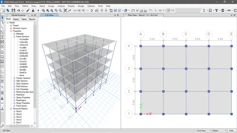
Fig H: Model B.
- Now check whether model B is assigned with the loads which was similarly assigned to model A. To do so click on Show frame load assign icon on the ribbon and then select the load pattern as assigned and clikc on apply. We can see that the load is being assigned to all the stories as seen in fig I.
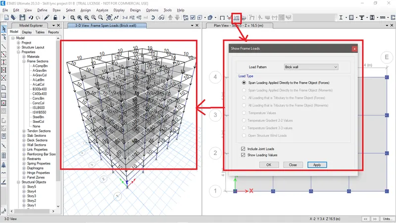
Fig I: Check of load assigned in the structure.
- Similarly moving ahead in creating Building C. In Model C the column size will be changed to 550X300 and oriented in X direction as shown in fig J.
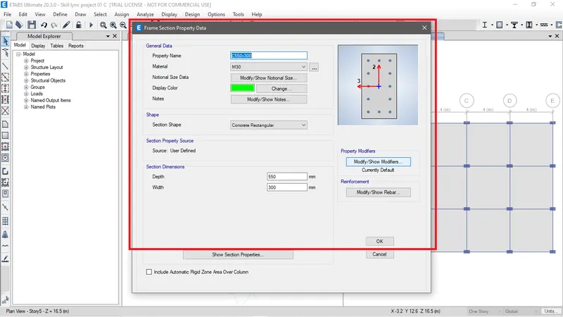
Fig J: Column modified to 550X300.
- Fig K shows the model C is being created as described.
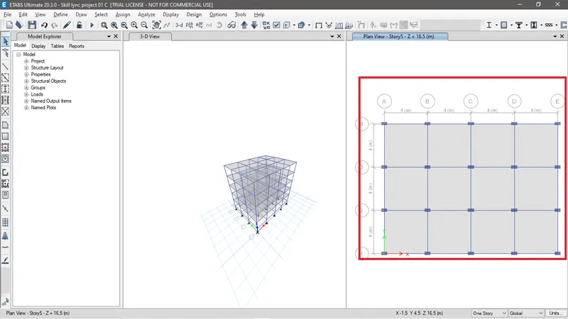
Fig K: Model C
- Moving ahead to create model D. Here in this model the only changes is that the orientation of the column will be at Y direction. To change the orientation to From X to Y direction first select all the columns and then go to Assign>Frame > Local axis as shown in fig L.
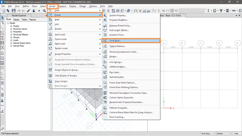
Fig M: Local axes.
- Check angle and type 90 degree angle and click on Ok as shown in fig M.
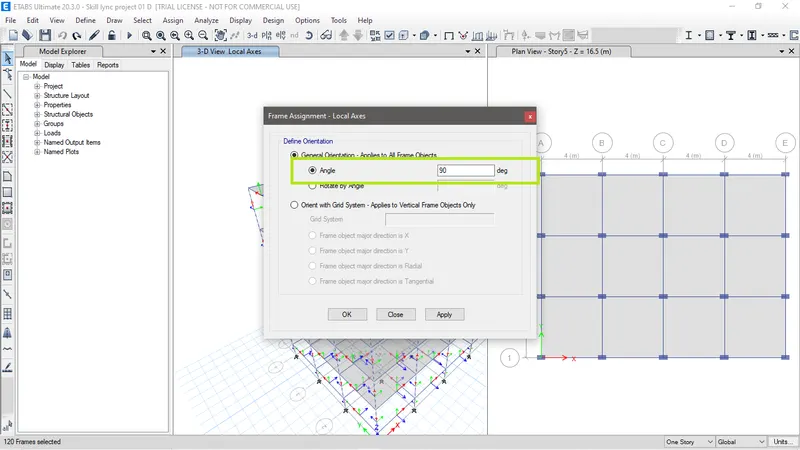
Fig L: Angle.
- In fig N we can see that the orientation of the column have changed to Y direction, hence the Model D is created.
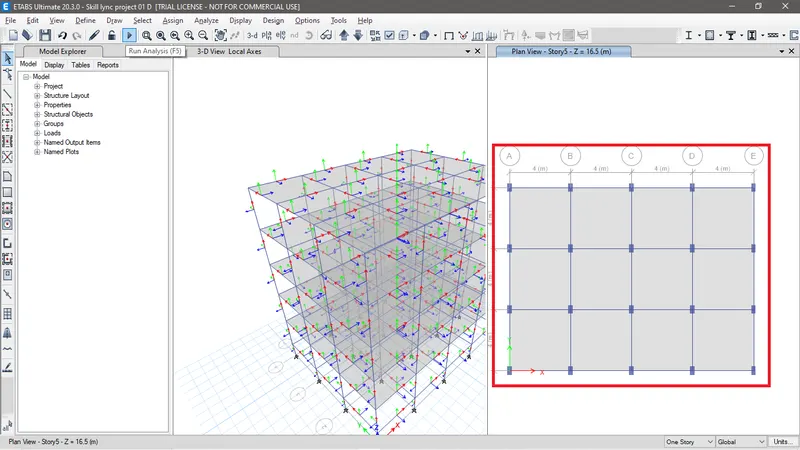
Fig N: Model D.
- Now moving ahead to create Model E. In model E will consist of 10 stories and stories 1 to 5 will be having column size 600 X 600 and stories from 6 to 10 will be having column of size 400 X 400. After creating stories and defining both sizes column, we will need to hide the beam and slab elements and make only storey from 6 to 10 visible. To hide beam and slab elements click on Select display options icon > and uncheck Beams and Floors and click on Apply. Beams and floors are now hidden as shown in fig O.
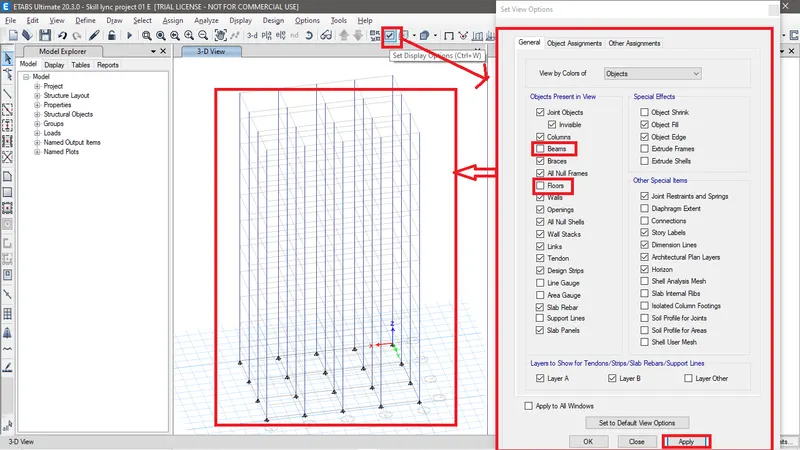
Fig O: Hidding Beam and floor elements.
- Now go to View tab > set building view limits. As shown in fig P.
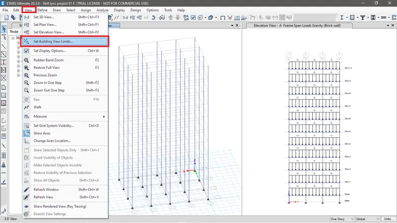
Fig P: Set building view limits.
- Now set Bottom storey as Storey 6 and Top storey as Storey 10, as shown in fig Q.
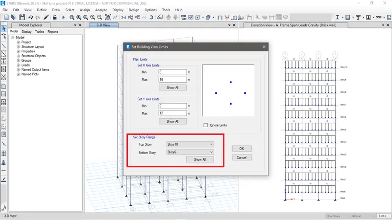
Fig Q: Set building view limits.
- Fig R shows building view limit from Storey 06 - Storey 10.

Fig R: Building view set storey 06 - storey 10.
- Now select column frame and assign column 400 X 400 to it. Fig S shows that column 400 x 400 assigned to storey 06 - storey 10.
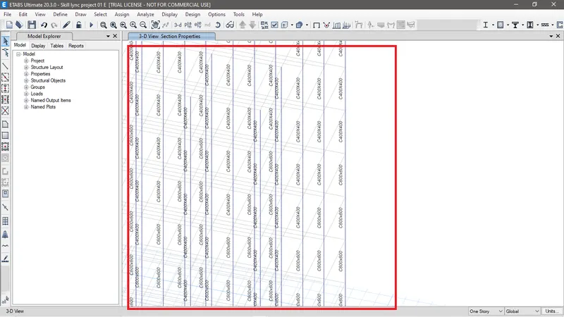
Fig S: Column 600 X 600 and column 400 X 400 assigned to required storey.
- Fig T shows Model E created.
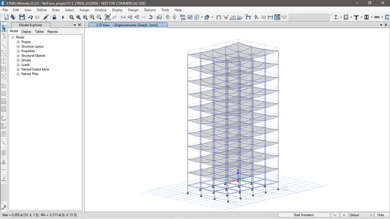
Fig T: Model E
- Now creating Model F having building structure of 10 storey and and all the column size of 600 X 600 as shown in fig U.
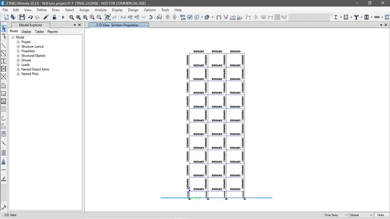
Fig U: Model F
- Now creating model G having 25 storey and Storey 1-10 having Column of size 800X800, Storey 10-20 having Column size 600X600 and Storey 20-25 having column size 400X400.. The Fig V shows Model G.
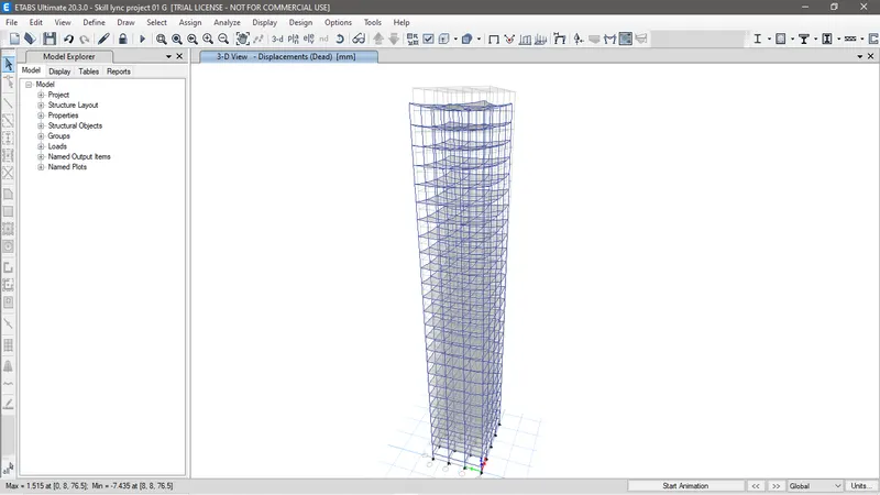
Fig V: Model G
- Now creating model H having 25 storey and all storey having column size 800x800. Fig W shows the model H.
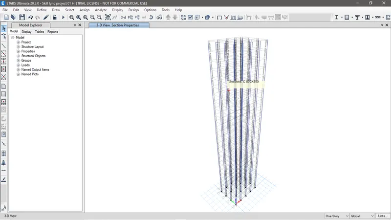
Fig W: Model H
- Now creating model I having 25 storey and impose load in this structure is increased by 10% more than the impose load assigned for model H. Fig X shows the model I.
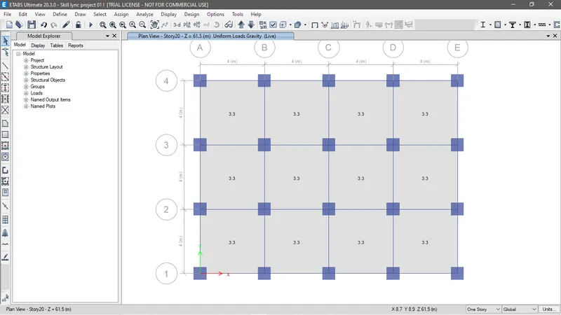
Fig X: Model I
- Now creating model J having 25 storey and impose load in this structure is increased by 20% more than the impose load assigned for model H. Fig Y shows the model J.
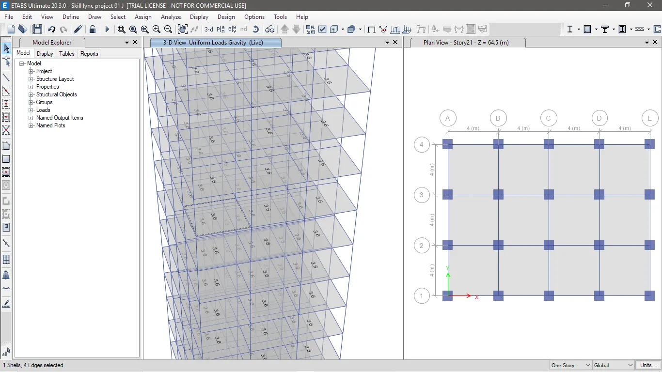
Fig Y: Model J
Results
1) Effect of stiffness on T: Compare fundamental natural periods of buildings E & F as well as G & H. Why is there a marginal or significant difference in the fundamental natural periods?
Building E (Varying column size) - 1.73 Sec.
Building F (Uniform column size) - 1.74 Sec.
Building G (Varying column size) - 4.18 Sec.
Building H (Uniform column size) - 4.42 Sec.
2) Effect of mass on T: Compare fundamental natural periods of buildings H, J and K. Have the buildings become more flexible or stiff due to change in mass?
Building H (25 storey building with 3 Kn/Sqm imposed load) - 4.42 Sec.
Building J (25 storey building with 3.3 Kn/Sqm imposed load) - 4.43 Sec.
Building K (25 storey building with 3.6 Kn/Sqm imposed load)- 4.44 Sec.
3) Effect of Building Height on T: How does the fundamental natural periods of Buildings A, B, F and H change with change in building height?
Building A (2 storey) - 0.5 Sec.
Building B (5 storey) - 1.04 Sec.
Building F (10 storey) - 1.74 Sec.
Building H (25 storey)- 4.42 Sec.
4) Effect of Column Orientation on T: How does the fundamental natural periods of Buildings B, C and D change with change in column orientation?
Building B (All floor column size 400X400) - 1.04 Sec.
Building C (All floor column size 550X400 oriented at X direction) - 1.15 Sec.
Building D (All floor column size 550X400 oriented at Y direction) - 1.12 Sec.
5)Effect of Flexural Stiffness of Structural Elements on mode shapes: Compare fundamental mode shape of Building B in two situations when flexural stiffness of beams relative to that of adjoining columns is very small versus when it is large.
Flexural stiffness of beam when very small in building B - 2.63 Sec.
To reduce the flexural stiffness in beam we need to go to Define tab>Section property >Frame section> Select the beam and click on modify/show property and then click on modify and show modifiers as shown in fig Z.
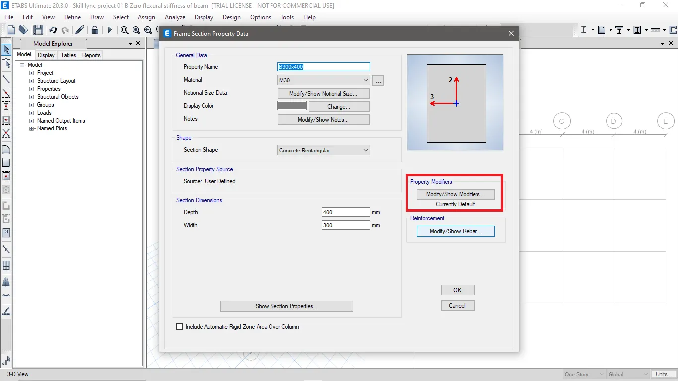
Fig Z: Modify/Show modifiers
Now change the moment of inertia about 2 axis and 3 axis to 10% to achieve low flexural stiffness in beam as shown in fig AA and click on Ok.
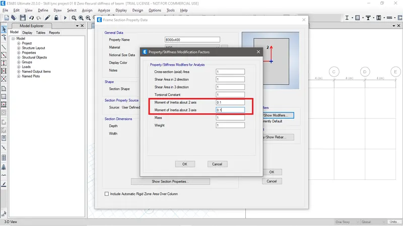
Fig AA: Moment of Inertia about 2 axis and 3 axis defined at 10%
We can notice in the Fig AB that the result for low flexural stiffness in beam is 2.63sec.
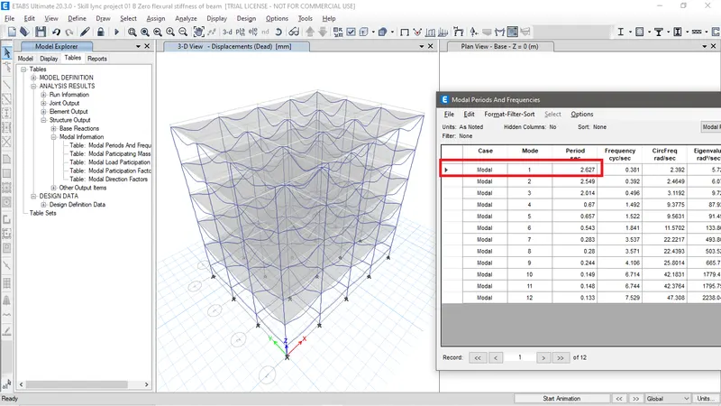
Fig AB: Result of Modal frequencies and period of the building B having low of flexural stiffness in beam.
Flexural stiffness of beam when are in regular in building B - 1.04 Sec.
6) Effect of Axial Stiffness of Vertical Members on mode shapes: Compare fundamental mode shape of Building H in two situations when axial cross-sectional area of columns is very small versus when it is large.
Axial stiffness of vertical member when very small in building H - 5.99 Sec.
Here to achieve small axial stiffness of vertical member we will define on 10% of axial area of the modifier in the column section as shown in fig AC.
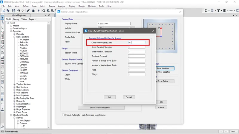
Fig AC: 10% of Axial area is defined in the column
Axial stiffness of vertical member when regular in building H - 4.42 Sec.
7) Effect of Degree of Fixity at column bases on mode shape: Compare fundamental mode shape of Building B in two situations when base of columns is pinned versus when it is fixed.
When building B is fixed - 0.94 sec.
When building B is pinned - 1.04sec.
Conclusion
- It is to be noticed that the effect of stiffness on T having hight time period when column is uniform in size when compared to varying column size and this is because column having uniform size increases the mass which increases the natural period of frequencies.
- The effect of mass on T having high natural period when the mass of the structure is more.
- In Effect of Building height on T we can see that the period increases in increasing storey. Here increase storey creates increase in mass hence increasing the natural frequencies of the structure.
- In Effect of column orientaion on T. We can see that there are slight changes when orientation of the column of same sizes are different but in actual if the sizes are same and orientation changes it should not affect the natural frequencies. The reason to occur this changes in frequency in this structure is due to change of bays in x and Y directions.
- In effect of flexural stiffness in beam and axial stiffness in vertical member we can see that the structure have significant changes in the natural frequencies when the value of it is lowered which is not safe for the structure.
- Finnally Fixed supports provide better natural frequencies of the structure when compared to Pinned support.