Project 1_Comparative study of different storey buildings for Seismic forces
PROJECT 1: FACTORS INFLUENCING THE DYNAMIC CHARACTERISTICS OF A BUILDING.
AIM:
- FACTORS INFLUENCING THE DYNAMIC CHARACTERISTICS OF A BUILDING
- FACTORS INFLUENCING THE NATURAL PERIOD OF A BUILDING
- FACTORS INFLUENCING THE MODE SHAPE OF OSCILLATIONS
DATA WE GET FROM THE REFRENCE OF 6TH CHALLENGE:
- Beam – 300x400mm
- Column – 400x400mm
- Slab – 150mm
- Grade of concrete: M30
- Grade of steel reinforcement bars: Fe415 loading
- Dead load on beams from infill wall: 10KN/m
- Live load on the floor: 3kn/m
STEPS:
We are going to design the 10 different building with the name of A,B,C,D,E,F,G,H,J,K. in this 10 building we are design the different storey height, different column size, different column orientation and performed a analysis to know the factor influencing the dynamic characteristic of building and after that we will conclude the all result below the project.
- STEP 1: DESIGN THE BUILDING A (G+2)
- Open the ETABS software and click on the new model to create a new model
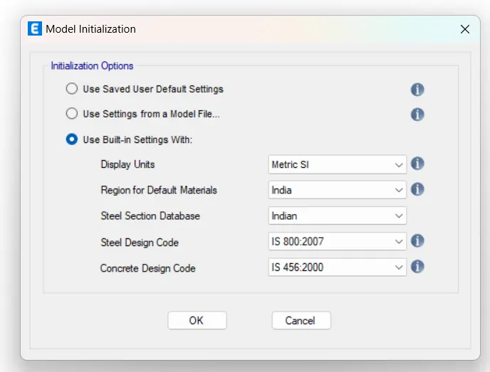
- Then go to the use built in setting and add the unit, material region, steel code and concrete code in model initialization panel and then click ok
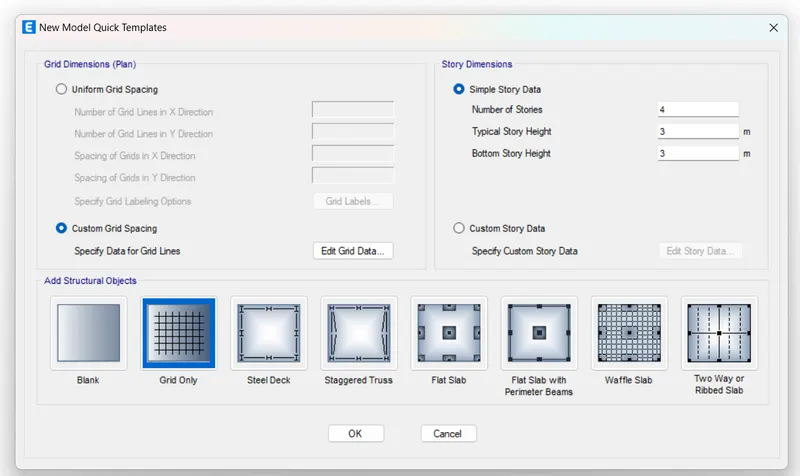
- Then after new window will open new template model in that window go to costume grid setting and edit the grid as per the requirements
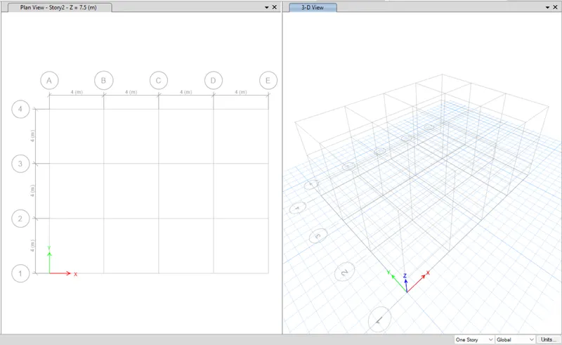
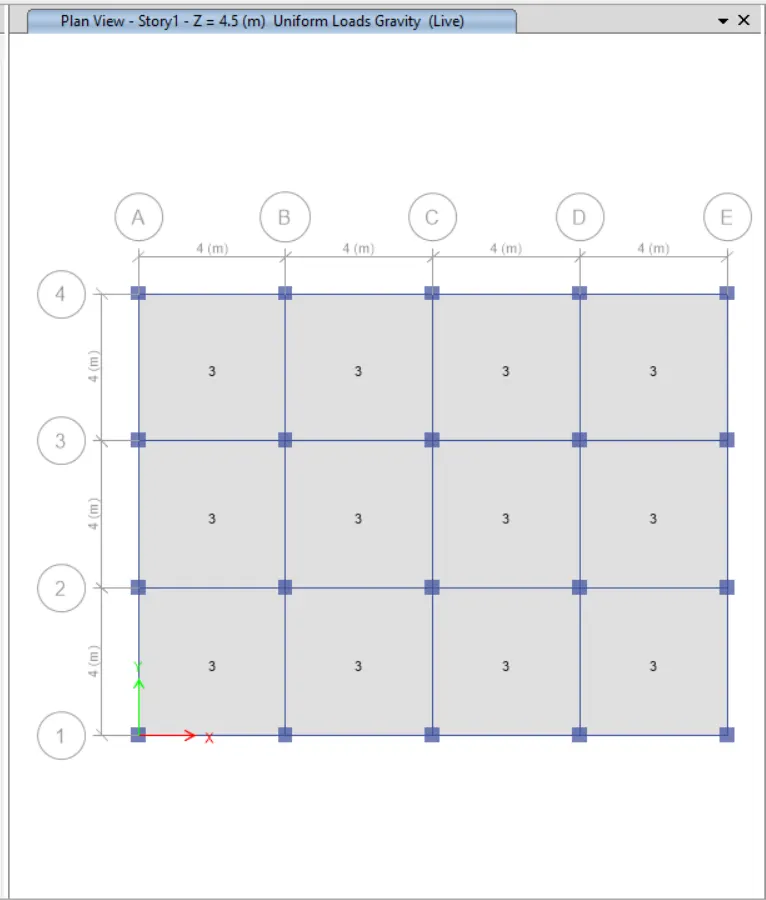
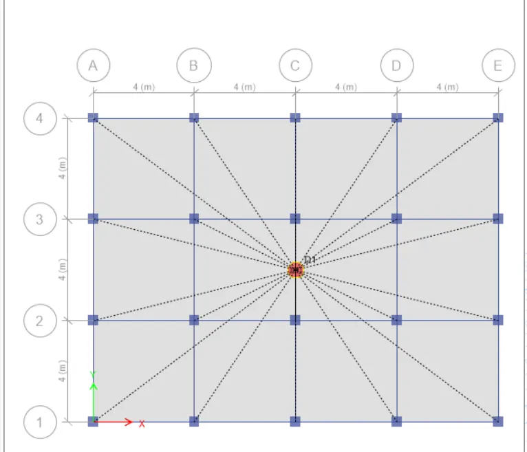
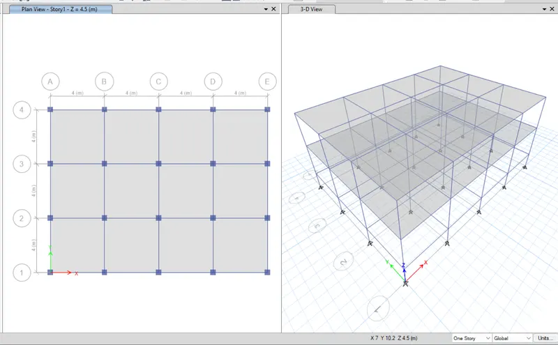
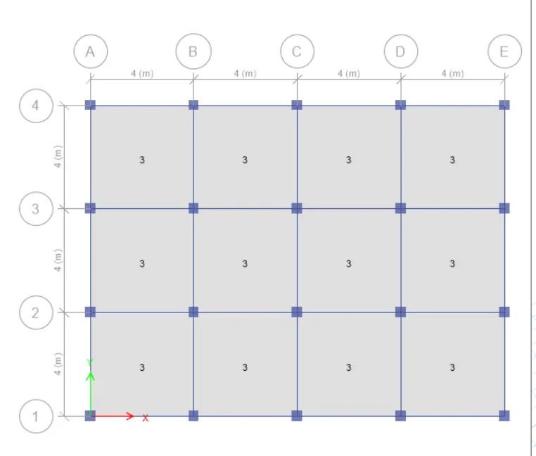
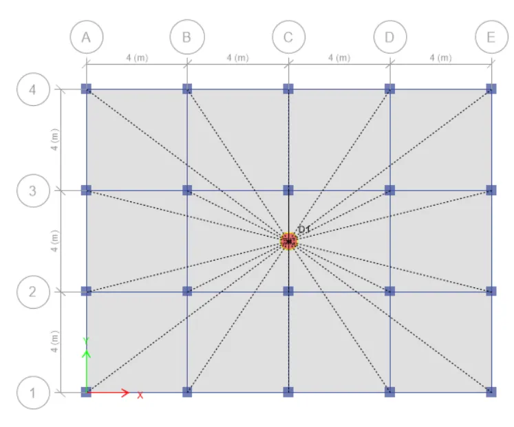
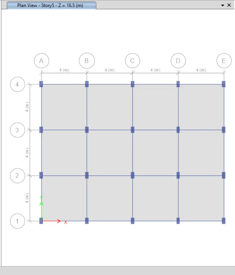
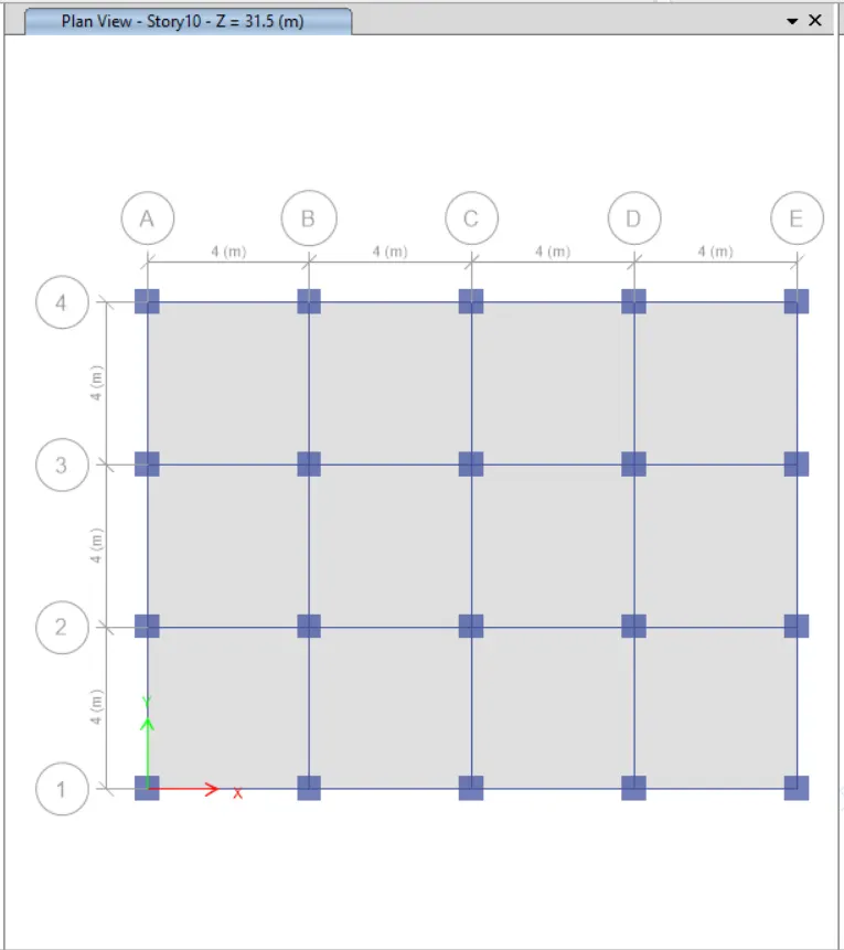
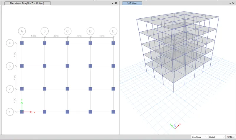
- We are making 5 grids in x direction and 4 grids in y direction with the equal spacing of 4m
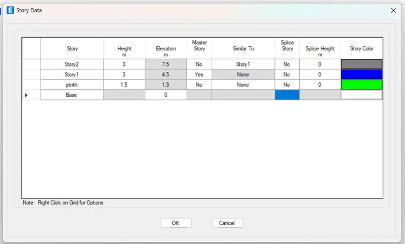
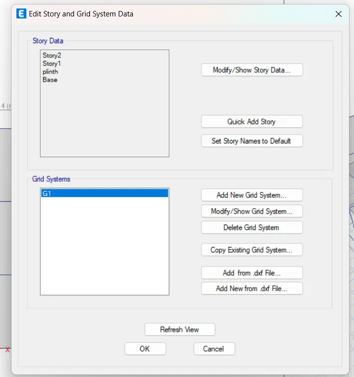
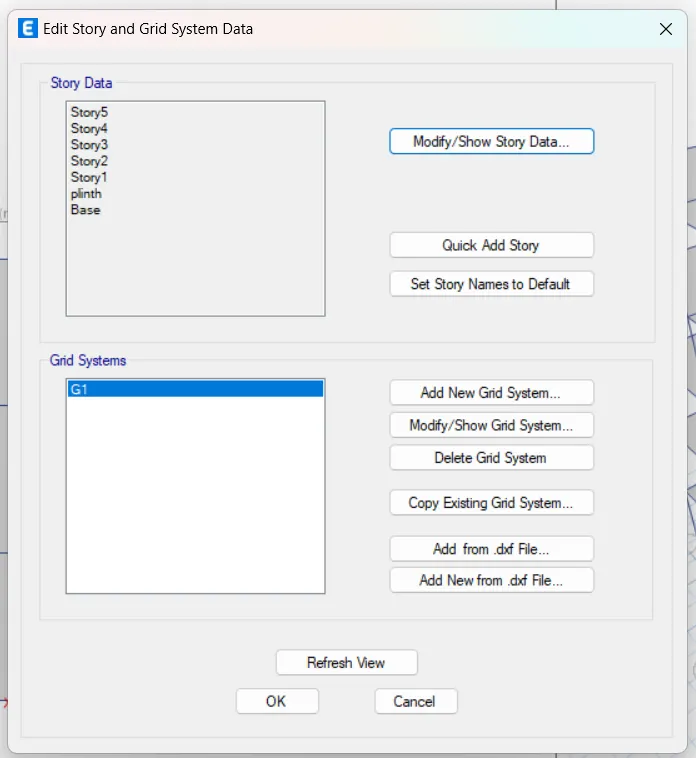
- Then go to custom story data to add the floors in the model
- As we need the only two storey delete the 3rd story and make a 1 story as a master story.
- Make a all story similar to story 1 and then press ok
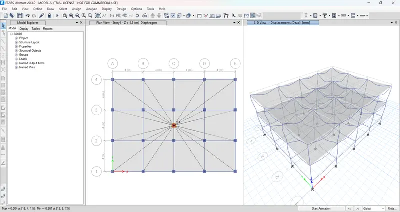
- After that two view will open one plan view and second is 3d view
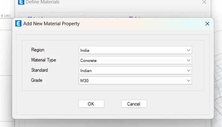
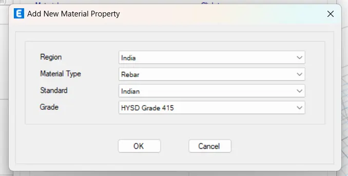
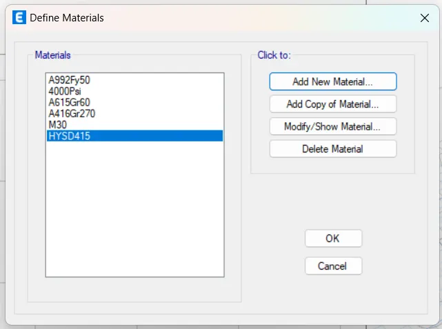
- Then add the material property by going define tab and open material property and create a rebar of HYSD415 and the M30 concrete
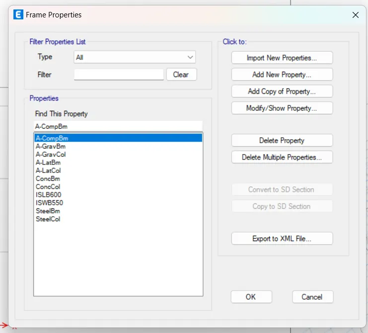
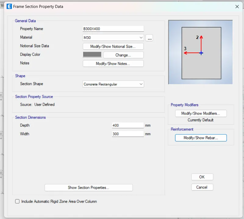
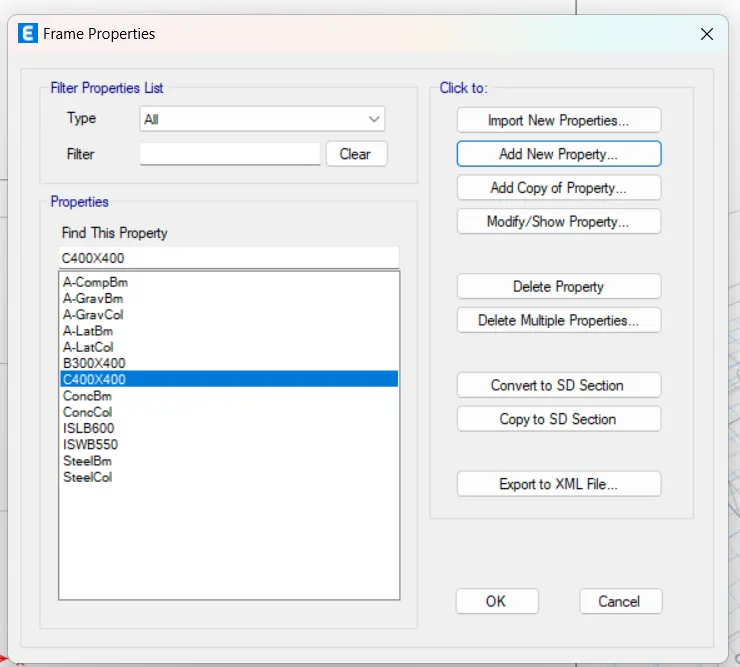
- Then go to the frame section and create a new beam with the design details of M30 concrete and HYSD415 steel.
- Create a beam with the depth 400 and with of 300 and press ok then beam will create
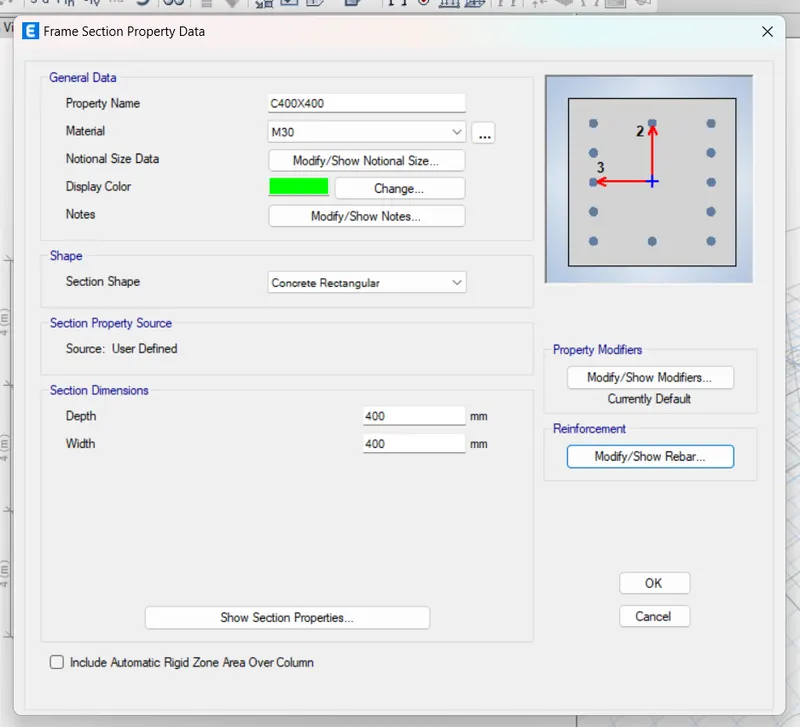
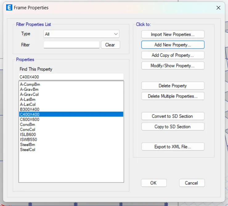
- Similarly create a column of the size C400X400 and press ok
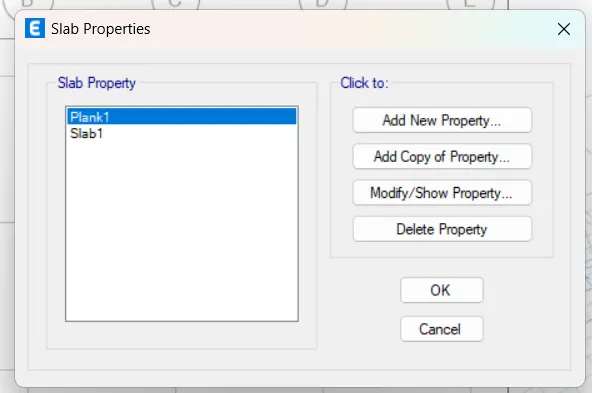
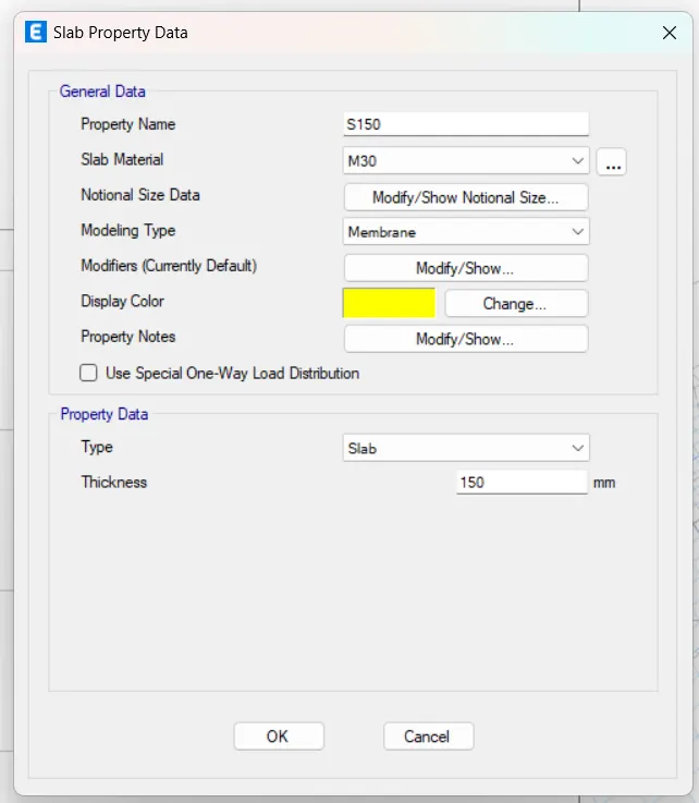
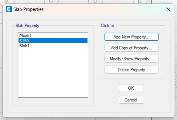
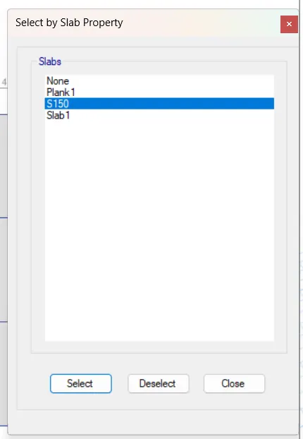
- Then to create a slab of 150 thickness go to the slab definition and create a slab S150
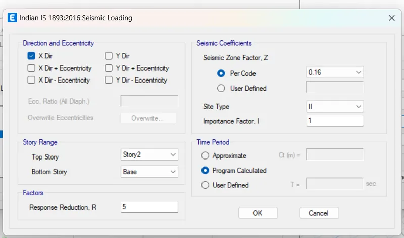
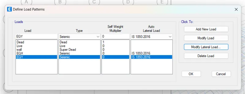
- Then create the load dead load, live load, wall load and earthquake load in x-direction and earthquake load in y-direction
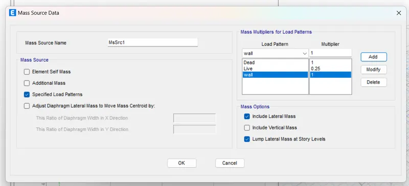
- Then define the mass percentage of the live load and dead load and wall load as per IS code
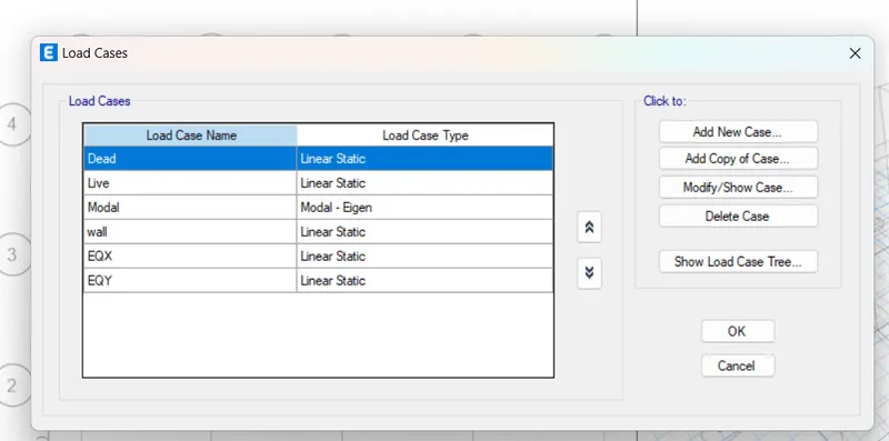
- Then go to the load case in define tab to see the load case as per given cheeked it
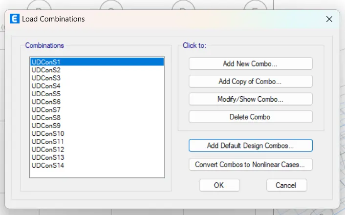
- Then create the load combination for analysis
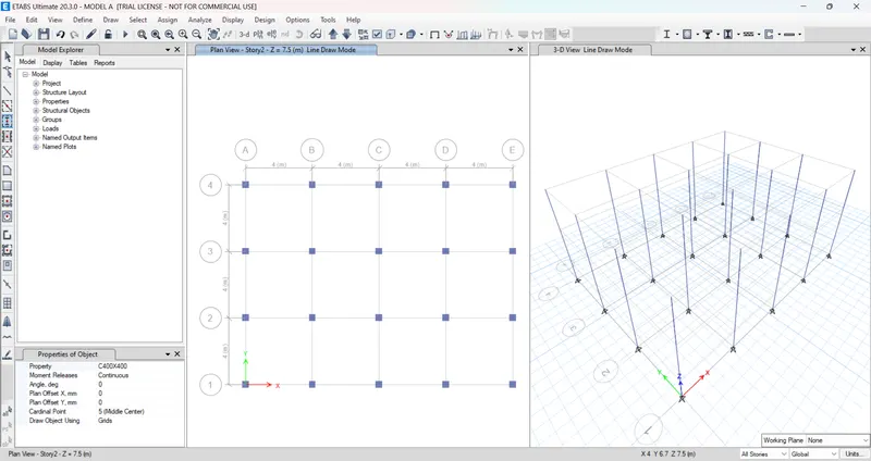
- After that the modelling stage will start to create the column first get select the quick draw option and select the all-storey option
- Then draw the column at the all the intersection of the grid
- Then select the beam and create the beam between all the column as per the requirement
- Then to create the slab first go to the first storey and select single storey option so that the there is slab created at the plinth level of the building
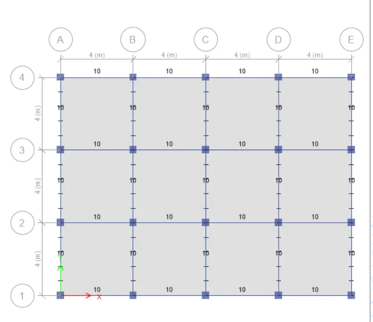
- Then to add the load first select the all the beam by using select option in ribbon tab
- Then assign the load of 10KN/m to the all the selected beam
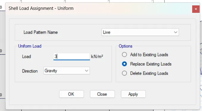
- Then assign the load of 3kN/m^2 to the all the slab by selecting slabs as similar as beams
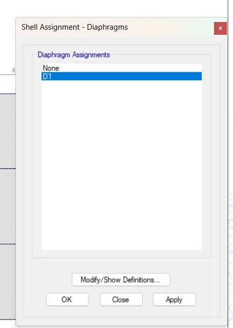
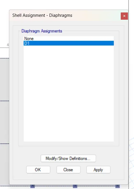
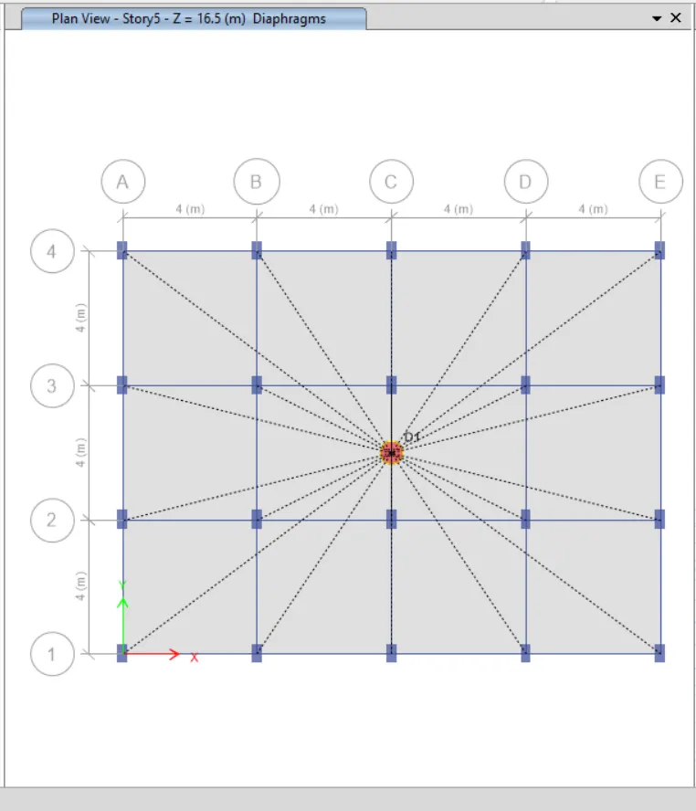
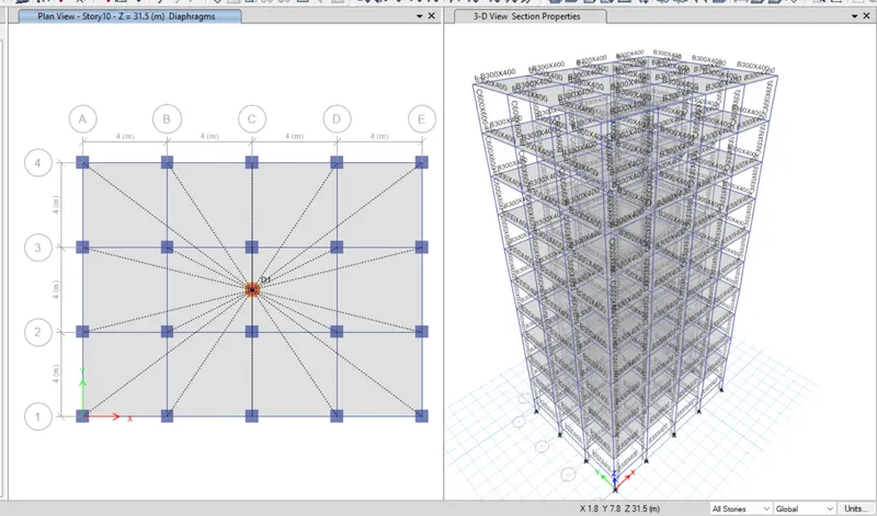
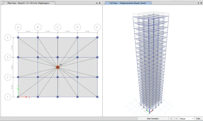
- Then assign the diaphragms select all the slab assign it
- After all the things are completed run the analysis before that save the model if your not saved it
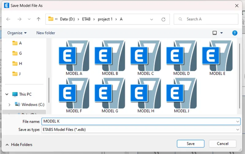
- Save the model as name MODEL A
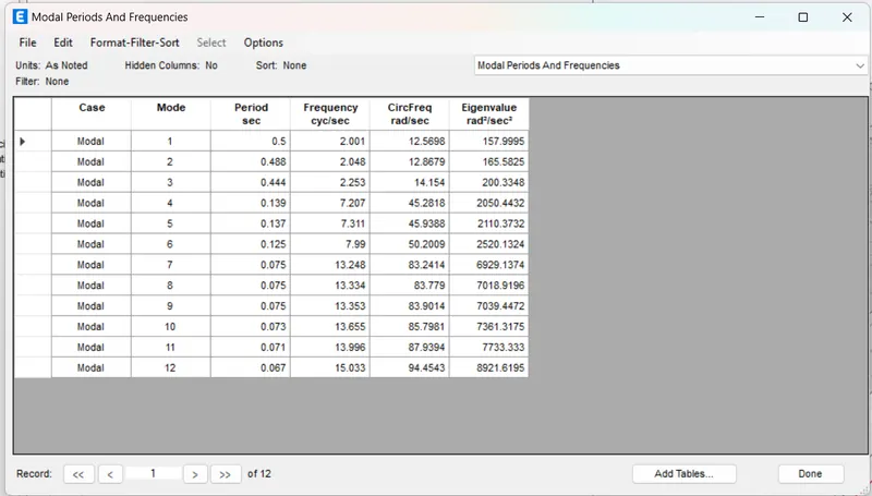
- Analysis is completed result is as per following.
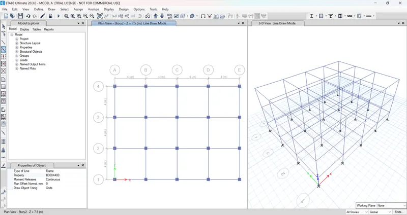
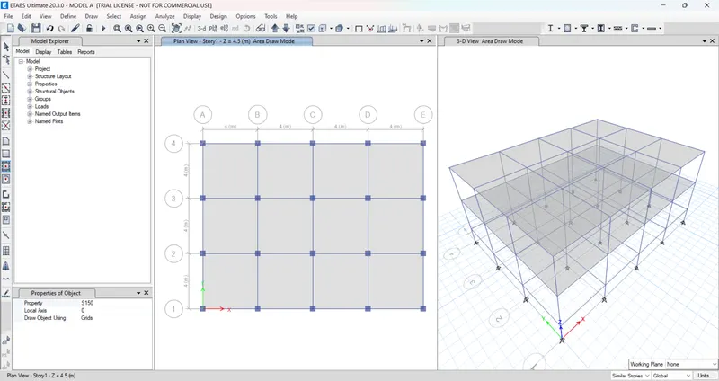

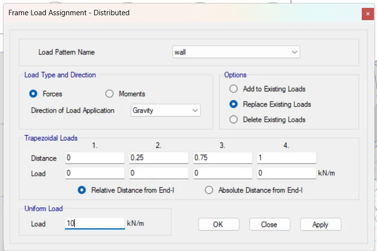
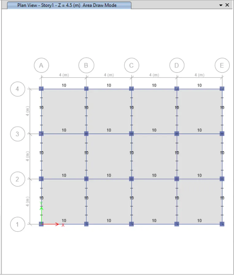
- STEP 2: DESIGN BUILDING B (G+5)
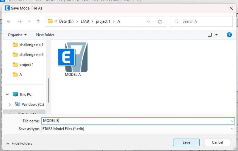
- First make a copy of the model a by save as option from files and name the new model as MODEL B
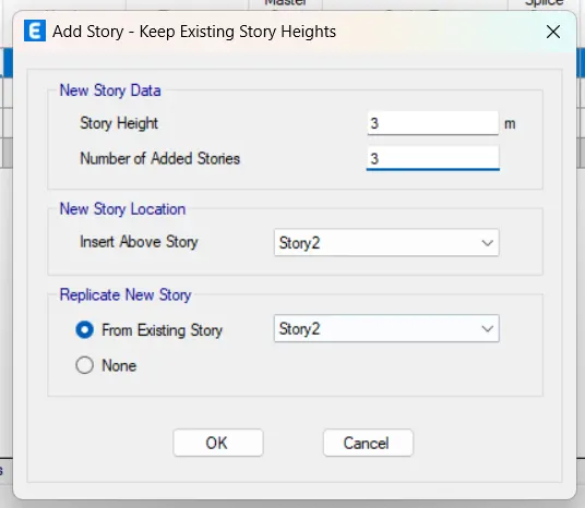
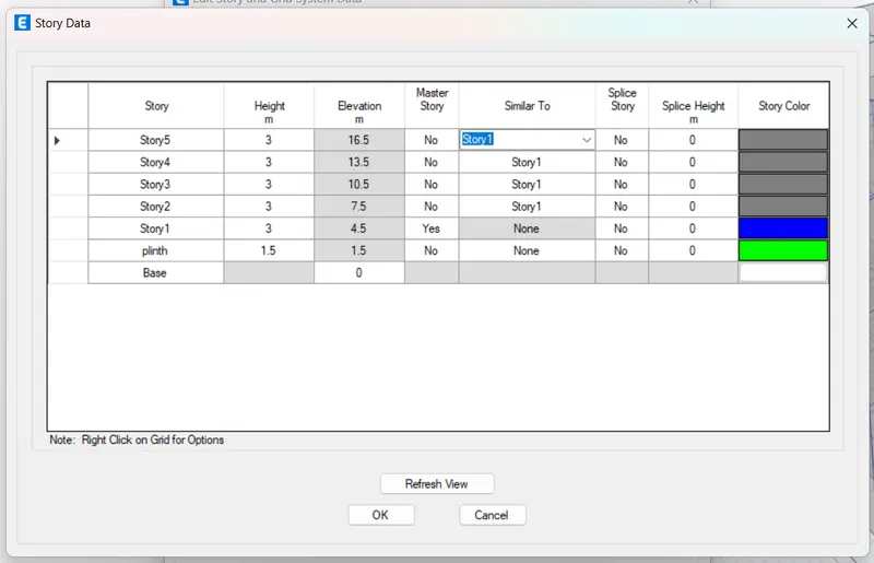
- Then open the model b and then edit the storey data as we required the g+5 storey
- Set the hight and story as per the requirement
- Also set each storey similar to the storey 1 as created in model A
- Then check for load assignment, from bottom ribbon in etabs, go to show frame shell loads one at a time
- Then add the diaphragm load, check if it is not assigned to the model
- After all the check have been made and the structure is ok, we can make the analysis
- Press F5 button to run the analysis
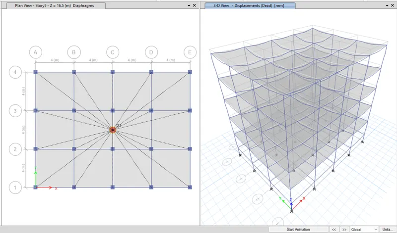
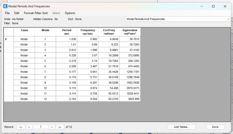
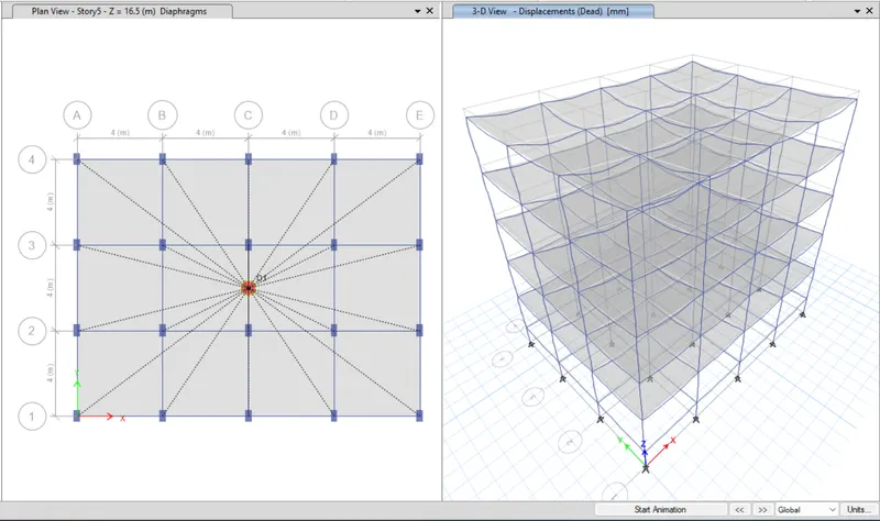
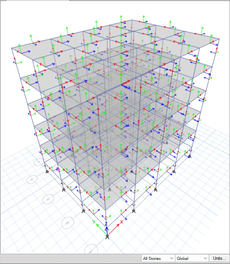
- After the analysis is completed the deflected shape of building will appear and we will know the analysis is completed.
- STEP 3: DESGN THE BUILDING C (G+5 WITH COLUMN ORIENTATION IN X DIRECTION AND CHANGE IN COLUMN SIZE)
- Create the copy of the model b and name it as MODEL C and save the model at proper location
- Then start the edit of column size and orientation
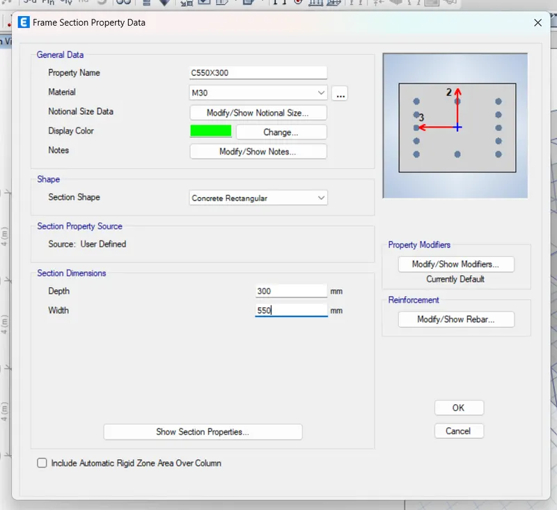
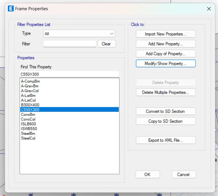
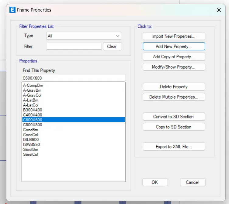
- Go to define>section properties>frame section
- Click on the modify and show properties option
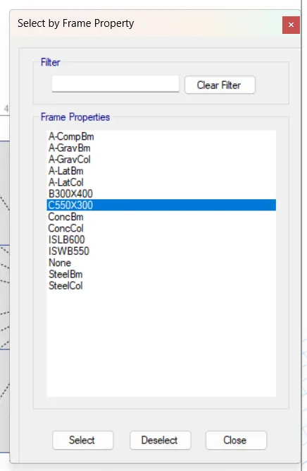
- Rename the column as we needed in model C550X300
- Then edit the breath and length by entering the values in the box
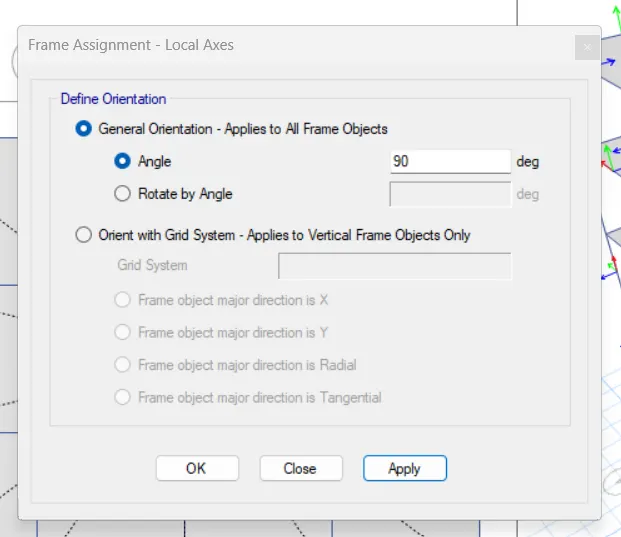
- We need to orient the column in the x direction
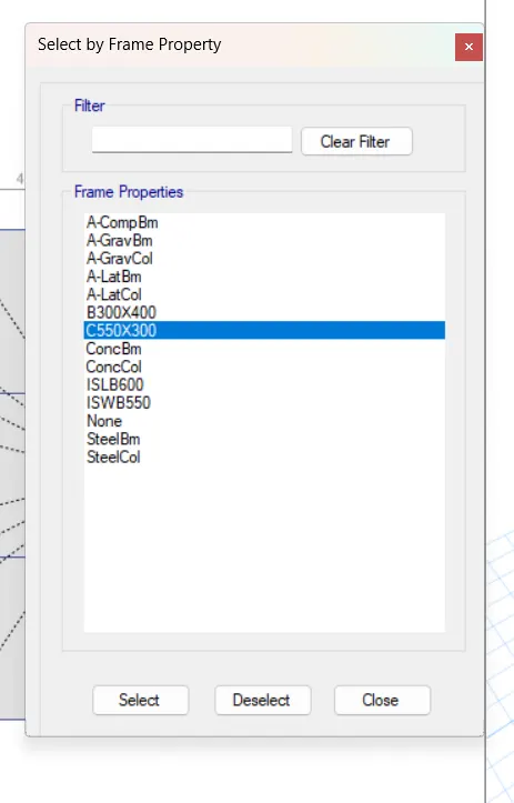
- Select the column section>go to assign local axis>rotate>90degree
- Then all the column will rotate in x direction
- After that check all the load is assigned or not
- Similarly check for the diaphragm is assigned or not if it is not assigned then assigned it
- Then run the analysis by pressing F5 button in keyboard
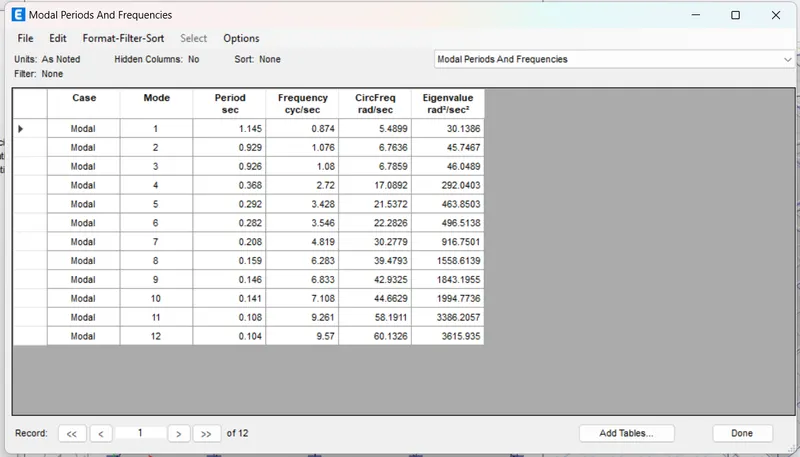
- After some time deflected shape of the building will appear that indicate the analysis has been completed
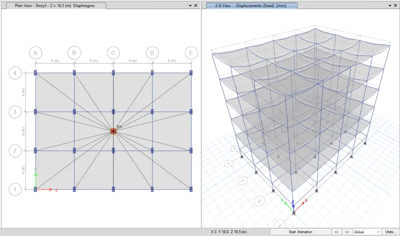
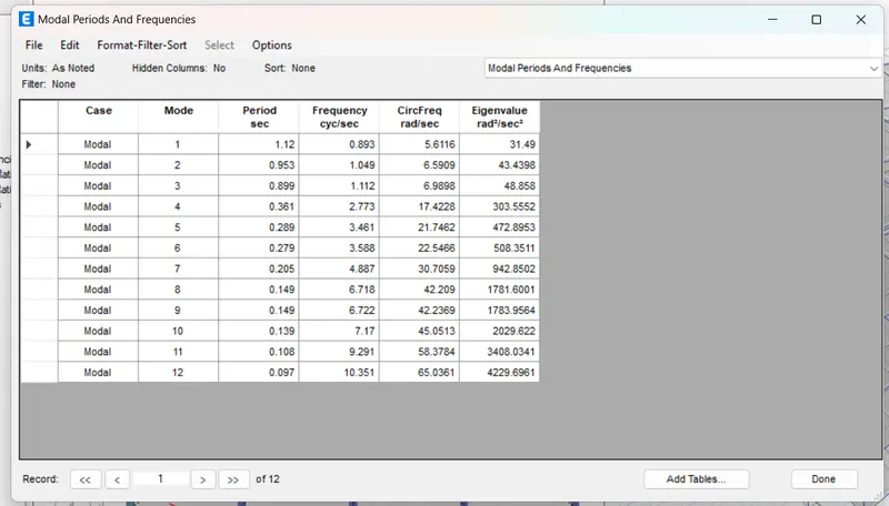
- STEP 4: DESIGN THE BUILDING D (G+5 WITH COLUMN ORIENTATION IN Y DIRECTION)
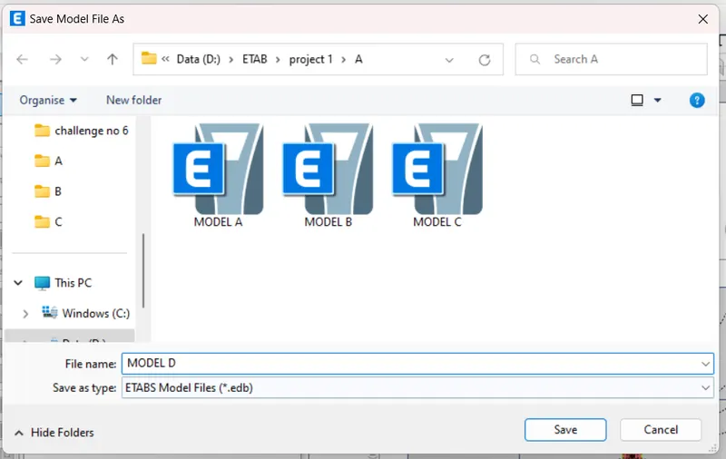
- first save the copy of the model c and name it as MODEL D
- So follow the same procedure as we did for the previous model
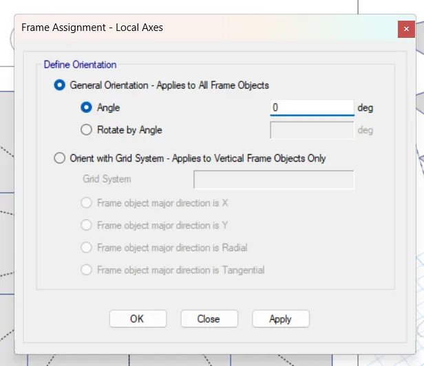
- Select column section assign the local axis and bring the origin to 0
- First select the column section> go to align local axis> rotate > 0 degree
- Then check for load assignment to the model
- Similarly, you need to check the diaphragm is assigned or not to your new model
- then run the analysis by pressing F5 button
- after deflected shape of the building will appear that indicated the analysis has been completed
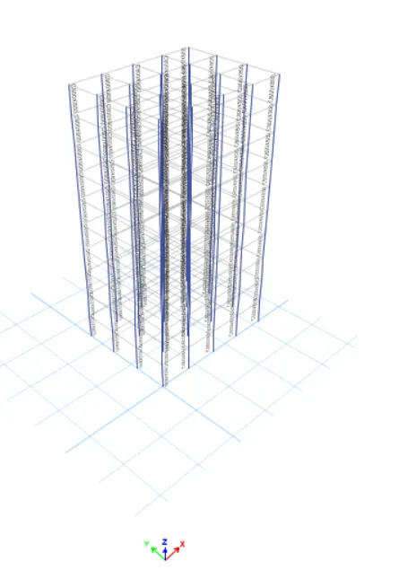
- STEP 5: DESIGN BUILDING E (G+10)
- First copy the model d and save as MODEL E in the proper location in the pc
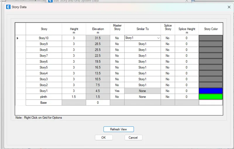
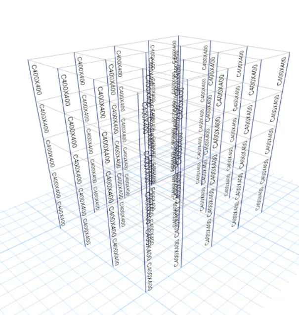
- There is change in column size in the building
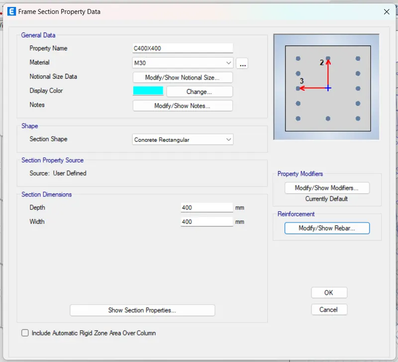
- Column size for top 5 story = 400x400
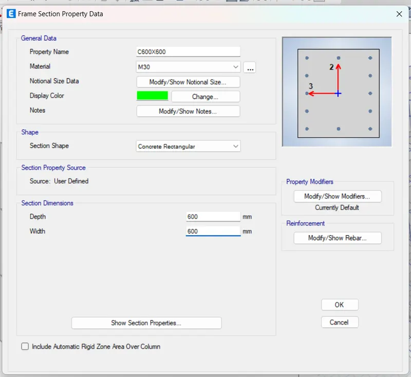
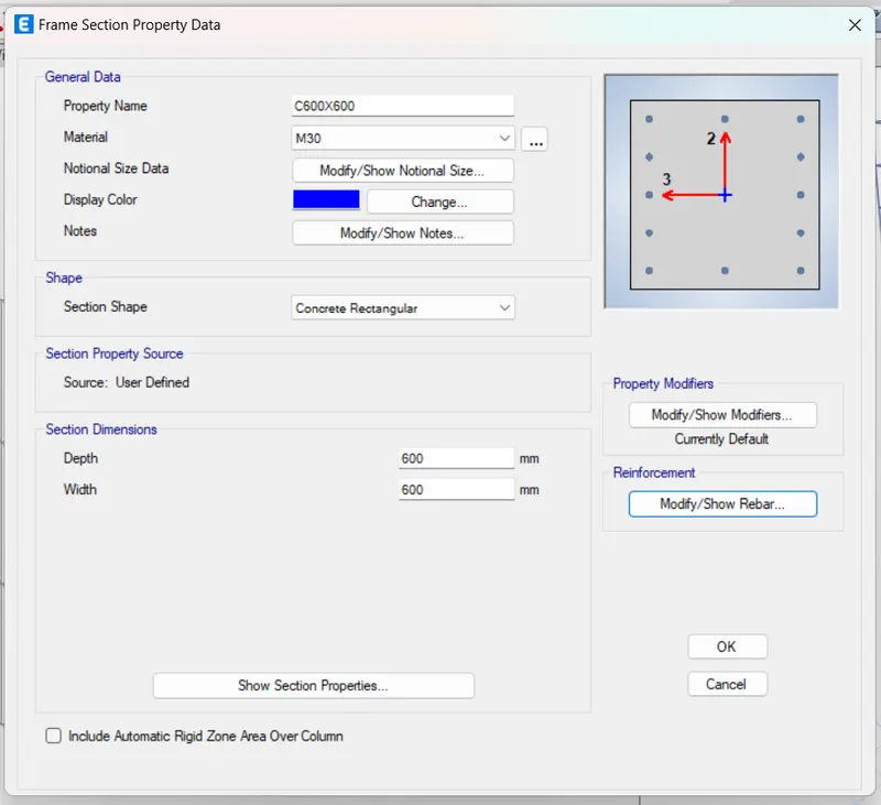
- Column size for bottom 5 story = 600x600
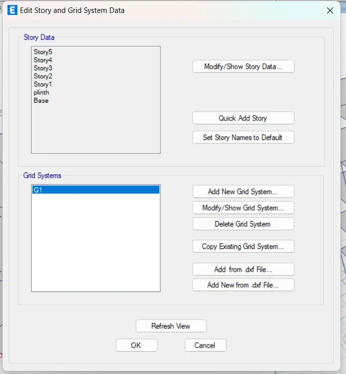
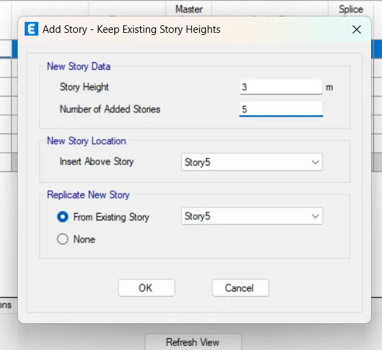
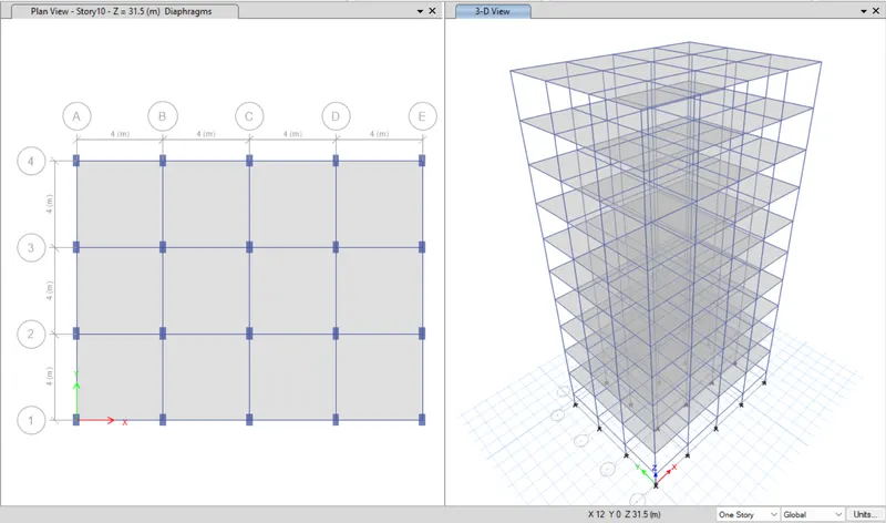
- Add up 5 new storey and set the model for building e
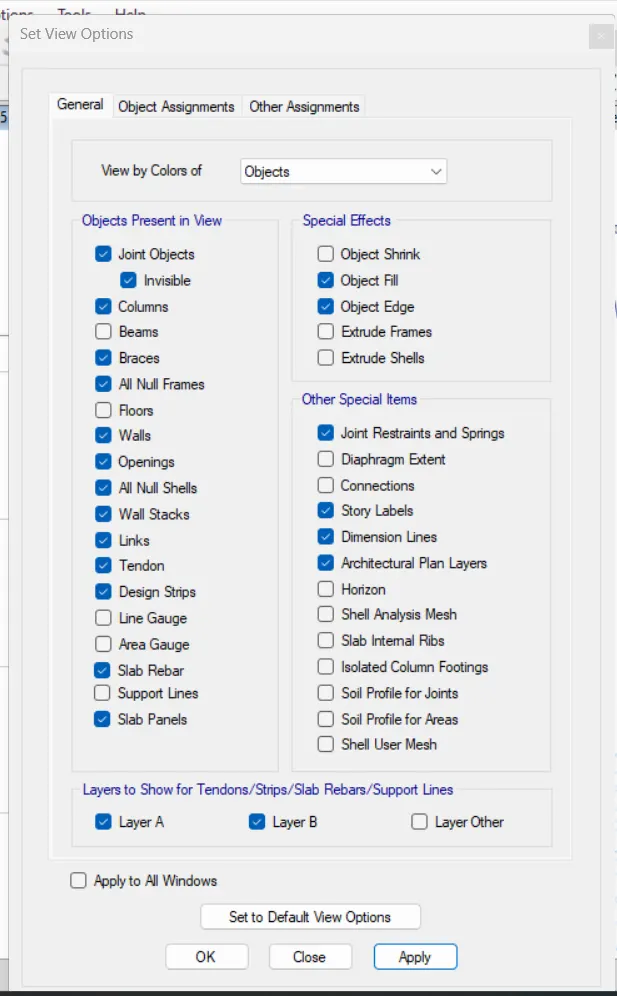
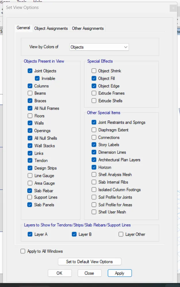
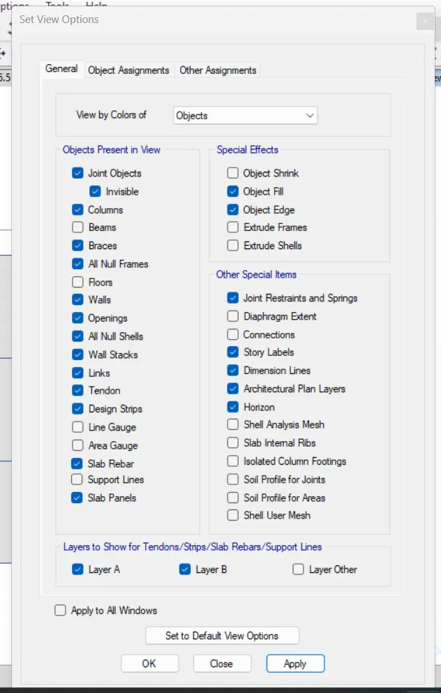
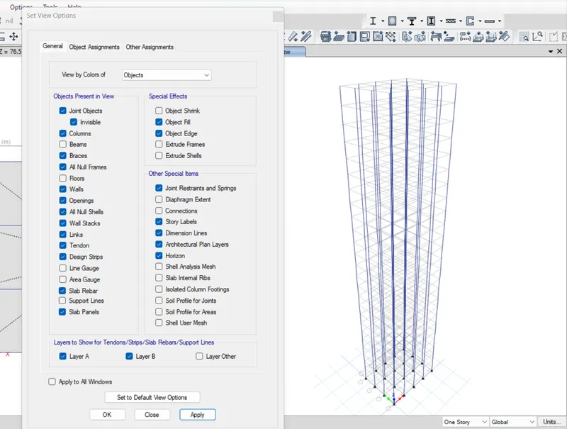
- First change the view settings of the model
- go view option settings and uncheck the structural members that we want to hide currently for modelling purpose
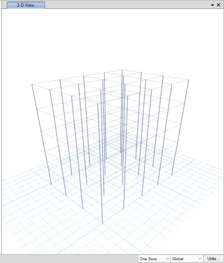
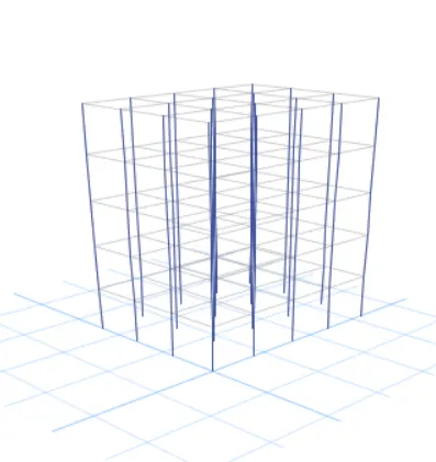
- So we to tools and uncheck the beam and floors in order to make only columns are visible
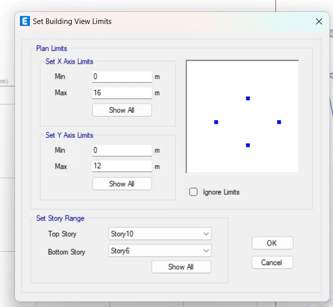
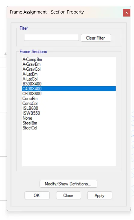
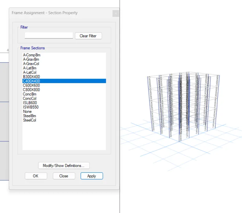
- Set the building limits select columns and assign them the required section
- Since we need different columns for top 5 floors and bottom five floors
- First, we need to set the limits bottom 5 floors and then vice versa
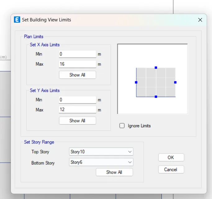
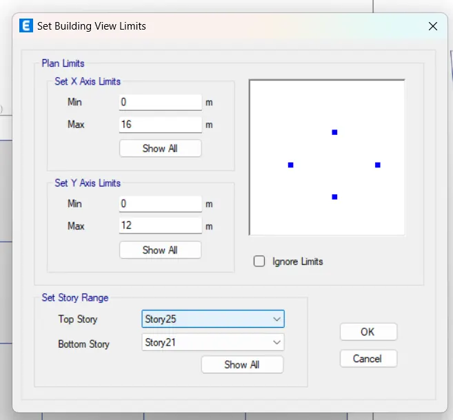
- You can go to edit>set the building limits
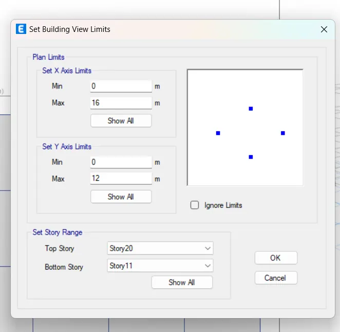
- Hence first set the limits to bottom 5> select all columns by holding the left click making the box around the entire model>go to assign and assign them to required column section
- Repeat the same procedure for remaining top 5 columns
- Then check for the load assignment
- Also check for the diaphragm is assigned or not to your model
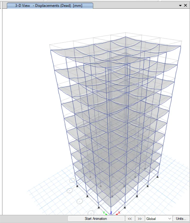
- Then run the analysis by simply pressing F5 button
- After few seconds it will show the deflected shape of the building which indicate the analysis is completed
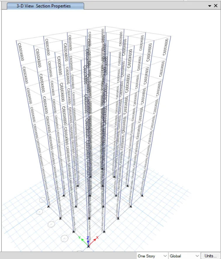
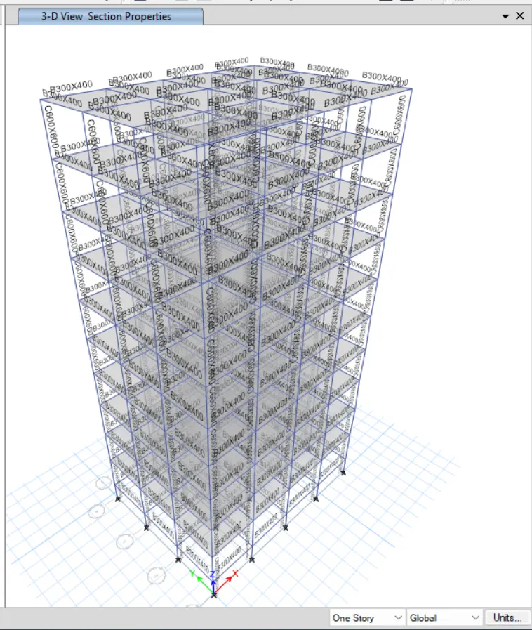
- STEP 6: DESIGN BUILDING F (G+10)
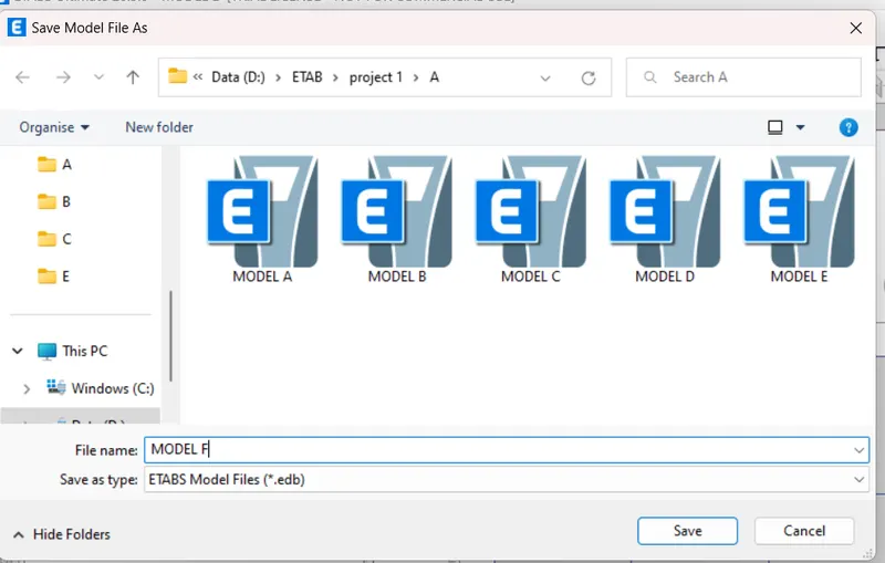
- First copy the model e and save as MODEL F at proper location
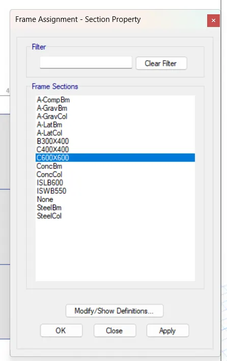
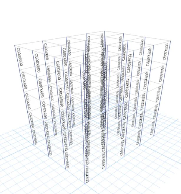
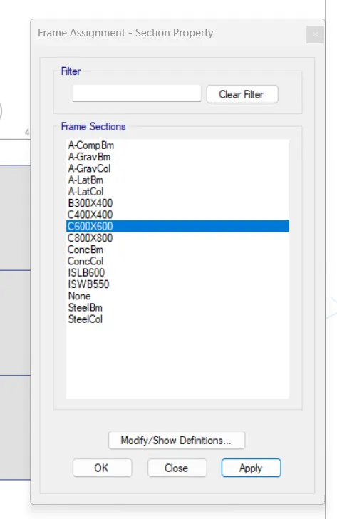
- We need to consistent column structure throughout the structure C 600X600
- The building has same column for entire structure so we need to adjust the view settings>hide beams and floor>select all the columns> assign them the frame section properties C600x600
- Then check for the load assignment
- And also check the diaphragm is assigned or notyou’re your new model
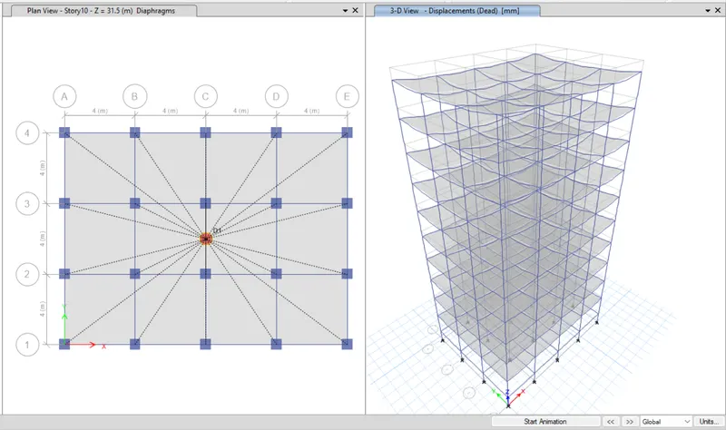
- Then to run analysis press F5 button to run the analysis
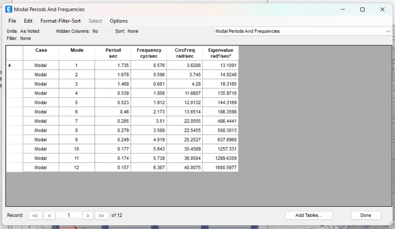
- After few seconds to deflected shape of the building will appear which indicate that analysis is been completed
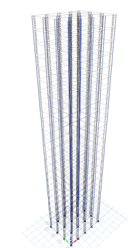
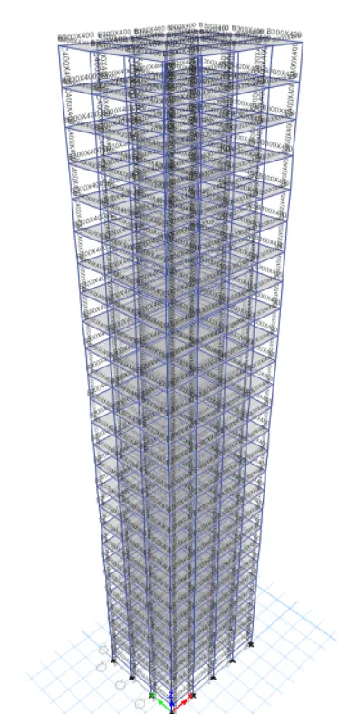
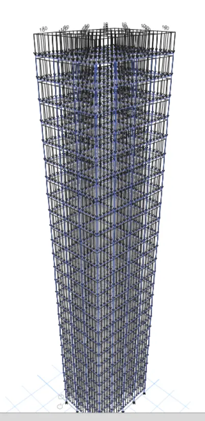
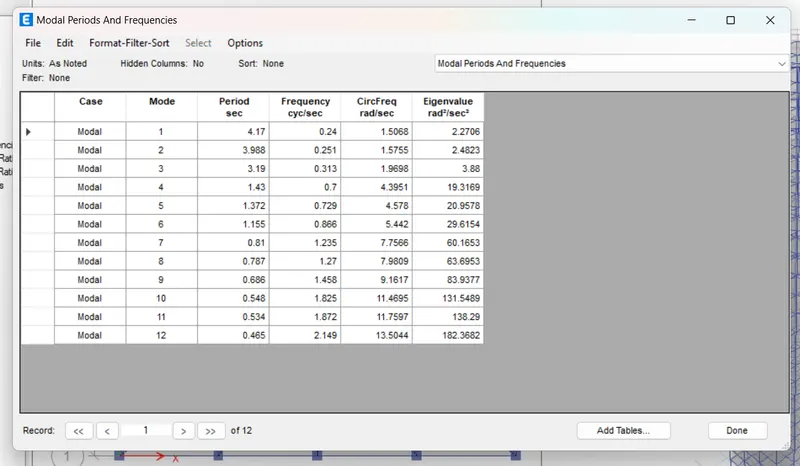
- STEP 7: DESIGN BUILDING G (G+25)
- First copy the model f and save as building g in proper location
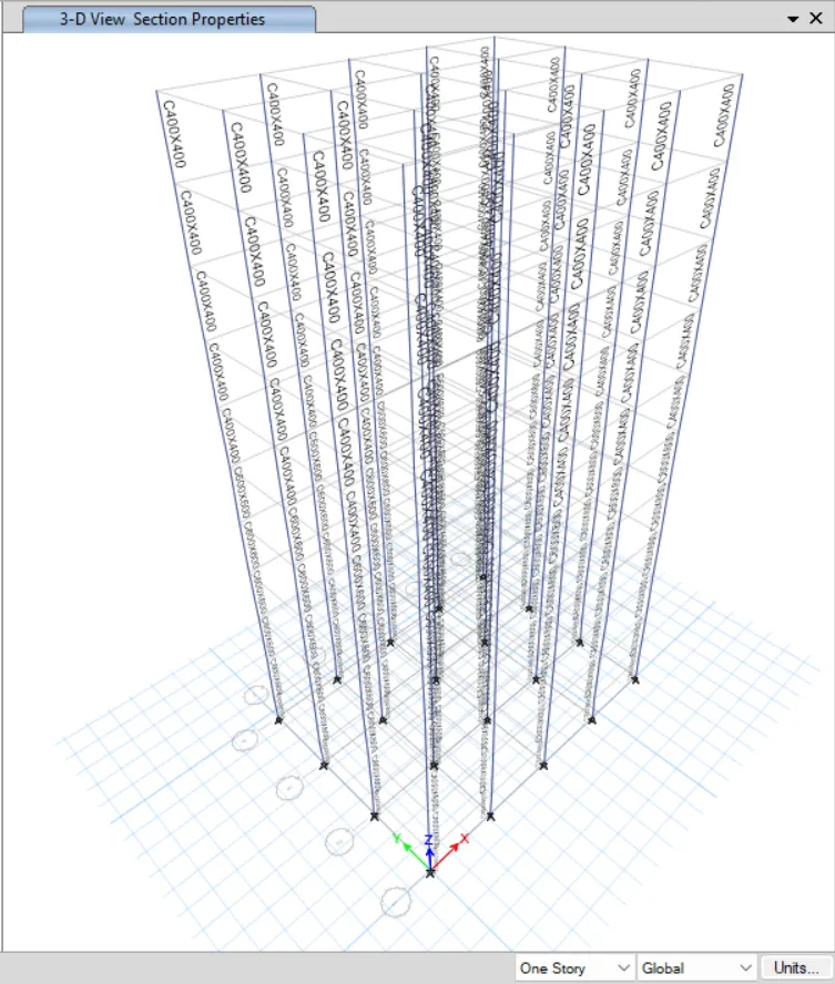
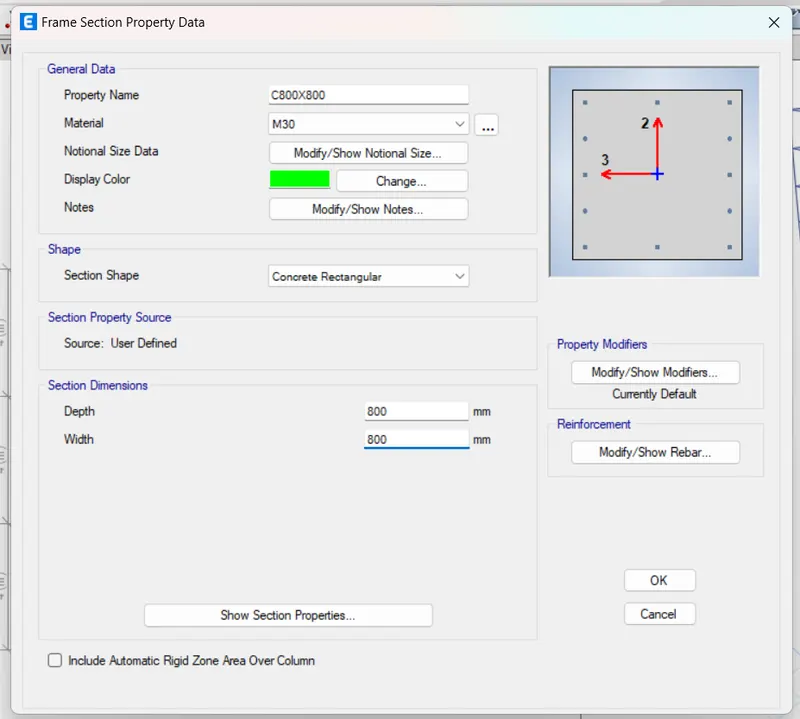
- Top 5 storey – C400x400
- Middle 10 storey – C600X600
- Bottom 10 storey – C800X800
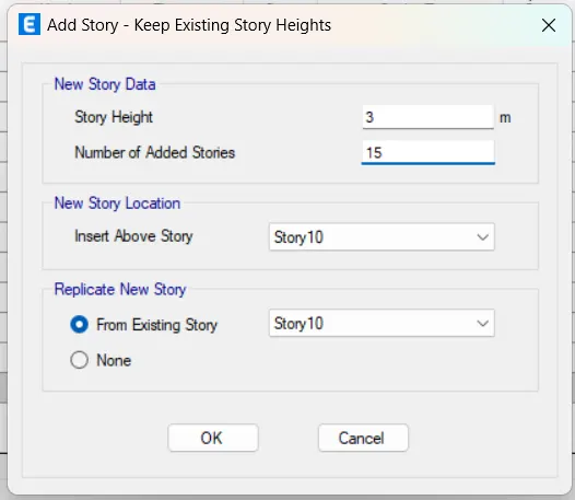
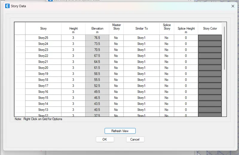
- First story data add up 5 new storeys
- Go to view edit setting
- Set limit 11-20
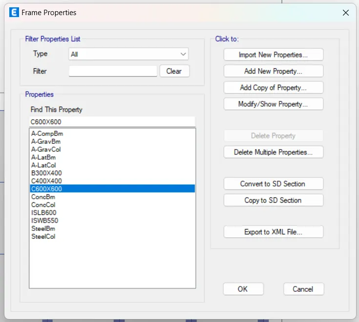
- Select all the column assigns C600X600 section
- Set building limit 20-25
- Select all the columns and assign the column C400x400
- Then check for load assigned from bottom ribbon in etabs, go to show frame loads one at a time
- Similarly check the diaphragm is assigned or not to your new model
- Then run the analysis by simply pressing F5 button
- After few seconds deflected shape of the building will appear indicates that analysis has been completed
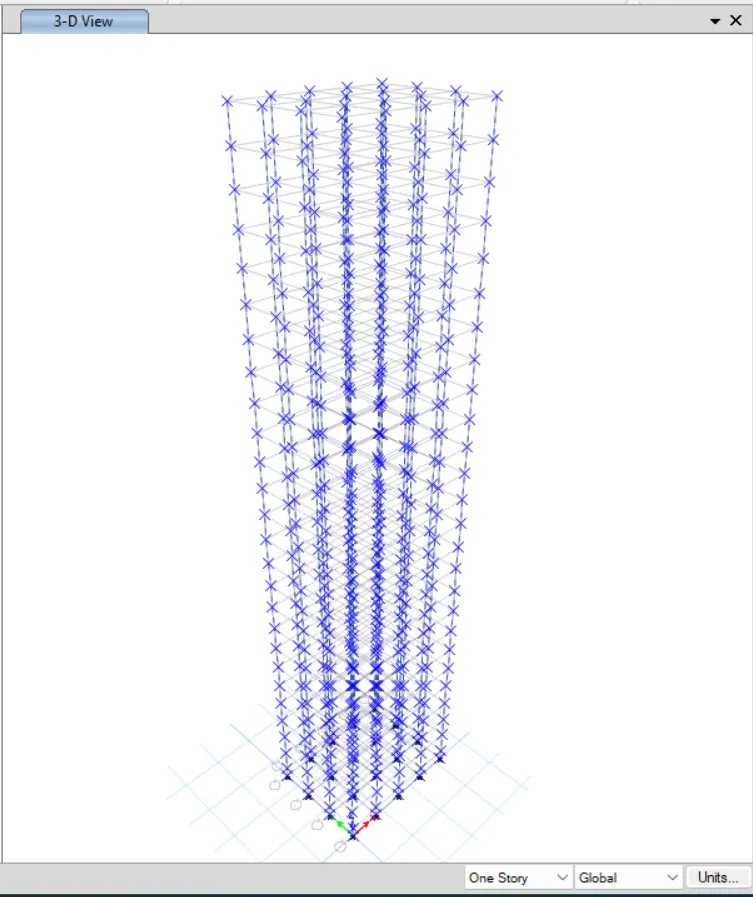
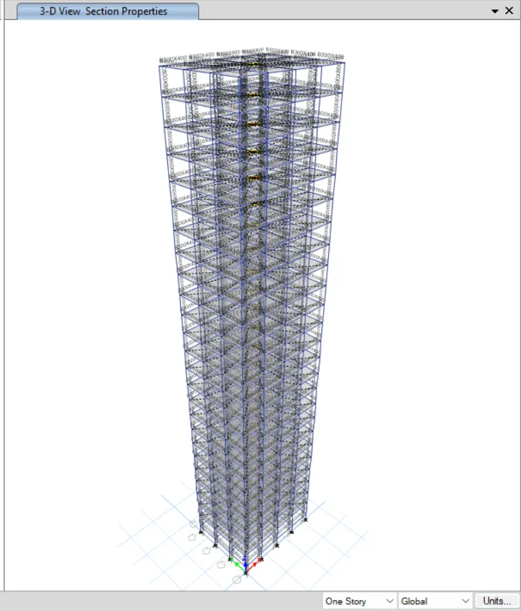
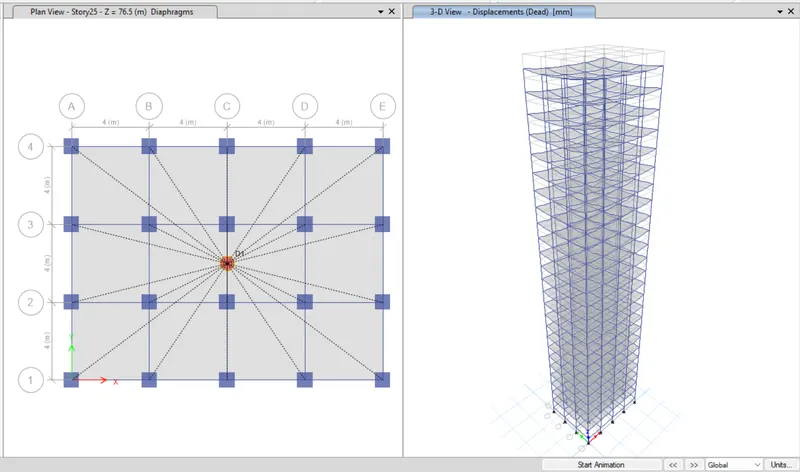
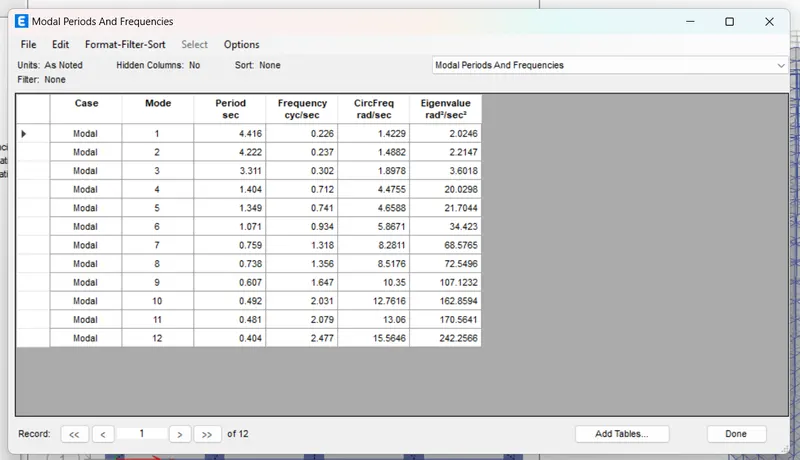
- STEP 8: DESIGN THE BUILDING H (G+25)
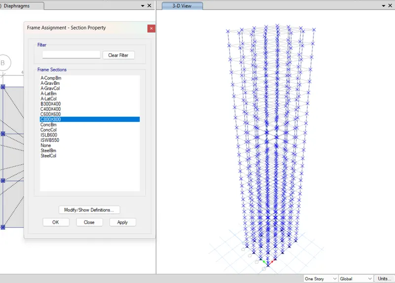
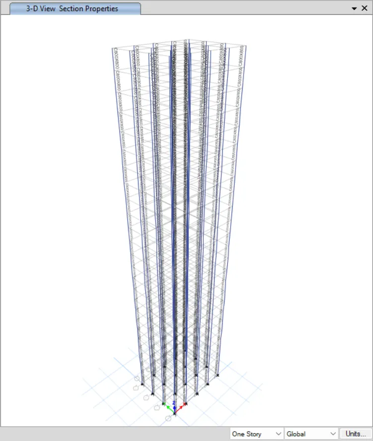
- Column size though out the building c800x800
- Entire structure which can be done by simple selecting all the columns>go to assign>select C800X800>CLICK OK
- Select all the column assign c 800x800 section
- Check for load assignment, from bottom ribbon in etabs, go to show frame loads one at a time
- Similarly you need to check the diaphragm is assigned or not to your new model
- Then run the analysis simply pressing F5 button to run the analysis
- It will take few seconds to show deflected shape of the building will appear which indicate the analysis has been completed
- STEP 9: DESIGN BUILDING J (G+25)
10% increment in the imposed loads
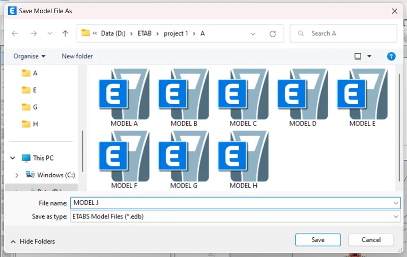
- First copy the model h and save it as a MODEL J at the proper location
- We don’t need to alter anything related to the modelling
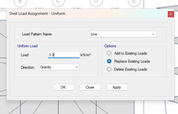
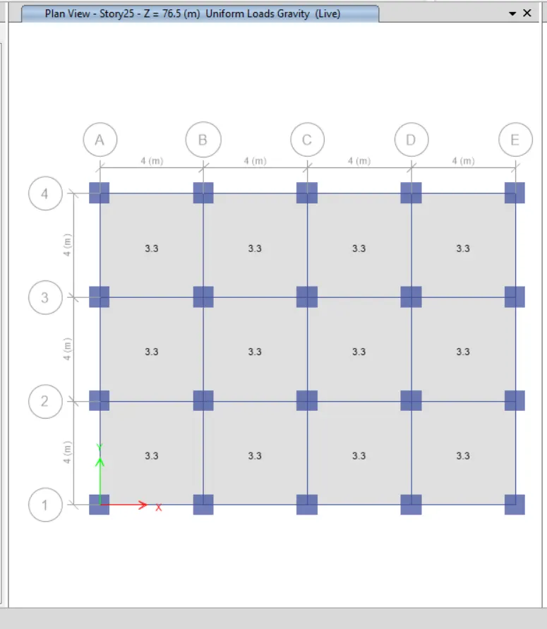
- We need to increased the imposed loads by 10% which is assigned as 3kN/m^2 on all slabs of the building
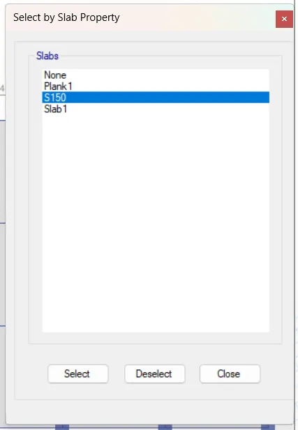
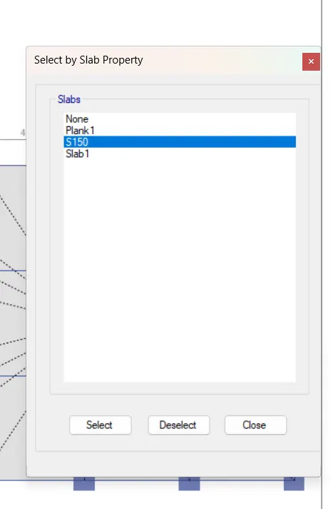
- Select the S150 slab section
- Go to assign>shell loads>uniform increase it by 10%
- Replace imposed load with 3.3Kn/m^2
- Then check for load assignment
- Similarly you need to check the diaphragm is assigned or not to your new model
- Now we can run the analysis by simply pressing F5 button
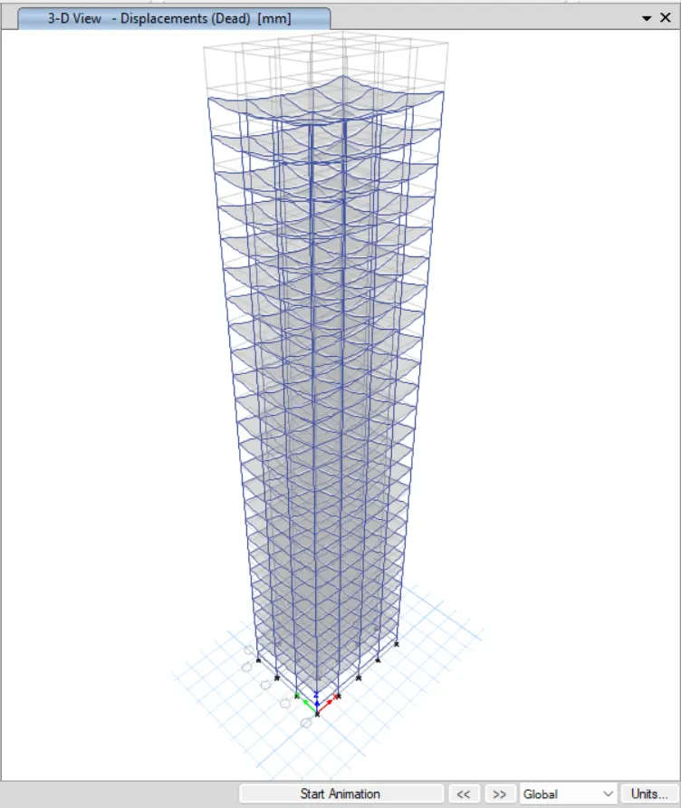
- It will take few seconds to show in deflected shape of the building will appear indicating that analysis has been completed
- STEP 10: DESIGN A BUILDING K (G+25)
20% increment in the imposed loads
- First copy the model j and save it as a MODEL K in appropriate location
- Building j is exact copy of model h
- We don’t need to alter anything related to modelling
- We need to increased the imposed loads by 20% which is assigned as 3Kn/m^2 on all slabs of the buildings
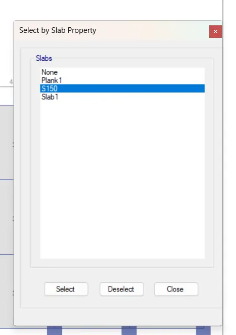
- Select the S150 slab section
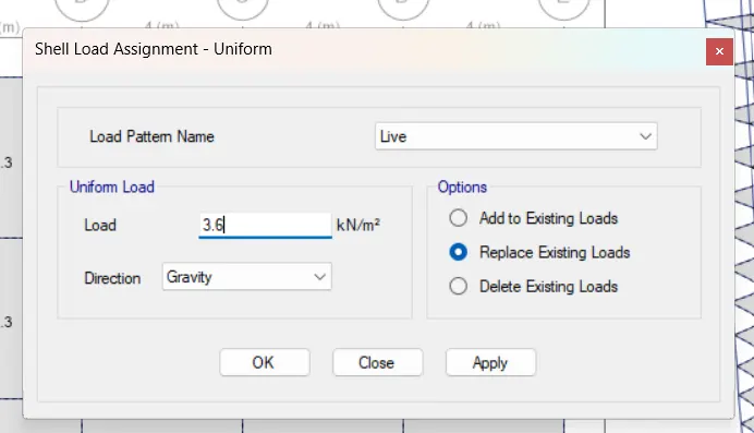
- Go to assign>shell loads>uniform increase it by 20%
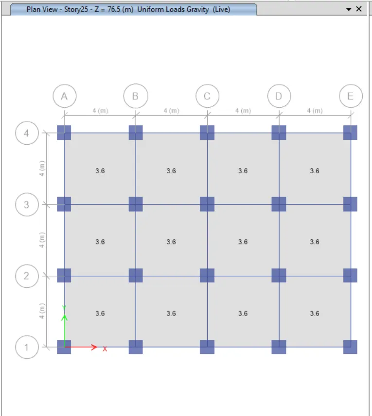
- Replace imposed load with 3.6kN/m^2
- Then before run analysis check for load assignment
- Similarly, you need to check the diaphragm is assigned or not to your new model run analysis
- Now after all the checks are done we can run the analysis
- It will take few seconds to show the deflected shape of the building will appear indicating that the analysis has been completed
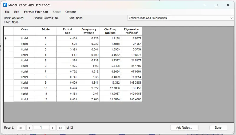
RESULT:
|
CRITERIA |
MODEL |
ANALYSIS RESULT |
CONCLUSION
|
|
EFFECT OF STIFFNESS ON TIME PERIOD |
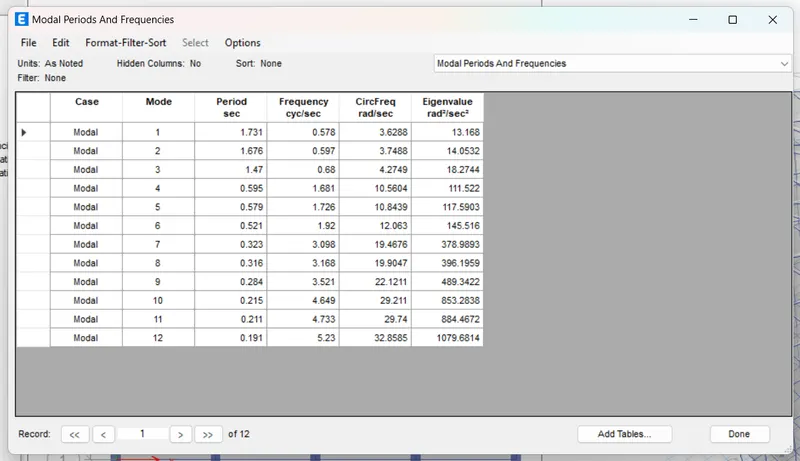
BUILDING-E (10 STOREY WITH VARYING COLUMN SIZE) |
1.73S
|
There is very less or no changes in time period with change in column size. |
|
|
BUILDING F (10 STOREY WITH UNIFORM COLUMN SIZE) |
1.73S
|
|
|
EFFECT OF STIFFNESS ON TIME PERIOD |
BUILDING-G (25 STOREY WITH VARYING COLUMN SIZE) |
4.17S |
|
|
|
BUILDING-H (25 STOREY WITH UNIFORM COLUMN SIZE) |
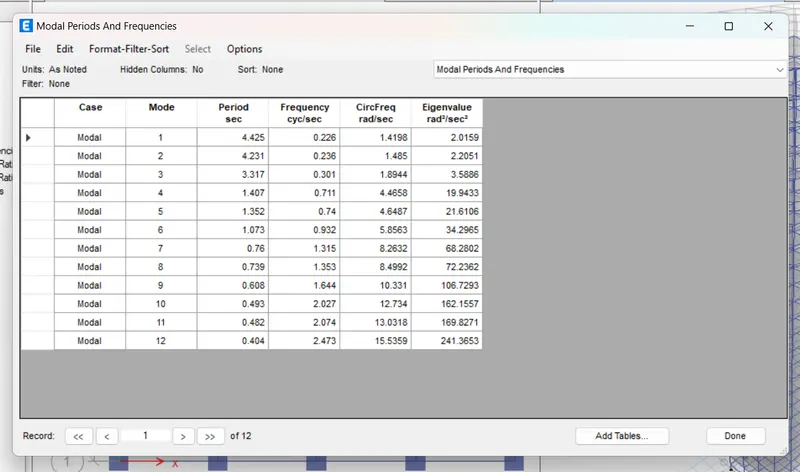
4.41S
|
|
CRITERIA |
MODEL |
ANALYSIS RESULT |
CONCLUSION
|
|
EFFECT OF BUILDING HEIGHT ON TIME PERIOD |
BUILDING A ( 2 STOREY) |
0.5S
|
Building height increases the time period increases it indicate that time period is directly proportional to the building height |
|
BUILDING B (5 STOREY) |
1.03S |
||
|
BUILDING F (10 STOREY) |
1.73S |
||
|
BUILDING H (25 STOREY)
|
4.41S |
|
CRITERIA |
MODEL |
ANALYSIS RESULT |
CONCLUSION
|
|
EFFECT OF MASS ON TIME PERIOD
|
BUILDING – H ( 25 STOREY WITH 3 KN/SQ.M Imposed Load)
|
4.41S
|
There is very less or no measure effect of mass on the time period. |
|
BUILDING – J ( 25 STOREY WITH 3.3 KN/SQ.M Imposed Load)
|
4.42S |
||
|
BUILDING – K ( 25 STOREY WITH 3.6 KN/SQ.M Imposed Load)
|
4.43S
|
|
CRITERIA |
MODEL |
ANALYSIS RESULT |
CONCLUSION
|
|
EFFECT OF COLUMN ORIENTATION ON TIME PERIOD |
BUILDING –B (ALL FLOOR COLUMN SIZE 400X400)
|
1.03S
|
There is very less effect of column orientation on time period |
|
BUILDING C (ALL FLOOR COLUMN SIZE 550X300)ORIENTED IN X-DIRECTION |
1.145S |
||
|
BUILDING D (ALL FLOOR COLUMN SIZE 300X550)ORIENTED IN Y-DIRECTION. |
1.12S |
|
RITERIA
|
MODEL |
CASE |
ANALYSIS RESULT |
CONCLUSION
|
|
EFFECT OF AXIAL STIFFNESS OF VERTICAL MEMBERS ON MODE SHAPE |
BUILDING-H |
AXIAL CROSS SECTION FOR COLUMN IS CLOSE TO NIL(ZERO AXIAL AREA) |
5.99S |
There is effect of axial stiffness of vertical member on mode shape |
|
|
FULL AXIAL CROSS SECTION FOR COLUMNS(REGULAR) |
4.41S |
|
CRITERIA
|
MODEL |
CASE |
ANALYSIS RESULT |
CONCLUSION
|
|
EFFECT OF DEGREE OF FIXITY OF COLUMN BASE ON MODE SHAPE |
BUILDING-B |
COLUMN SUPPORT PINNED (REGULAR) |
1.03S |
There is very less effect of degree of fixity of column base on mode shape |
|
|
COLUMN SUPPORT FIXED |
0.941S |