Project 1_Comparative study of different storey buildings for Seismic forces
AIM: b
INTRODUCTION: ETABS is an engineering software product that caters to multi-story building analysis and design. Modeling tools and templates, code-based load prescriptions, analysis methods and solution techniques, all coordinate with the grid-like geometry unique to this class of structure.
PROCEDURE:
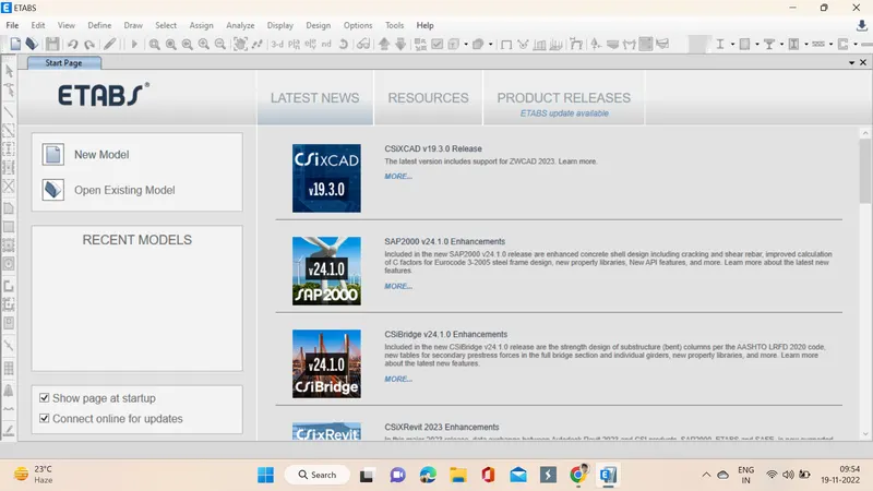
1. Open the ETABS softwar by double click on that icon, sofware interface opens as shown below.
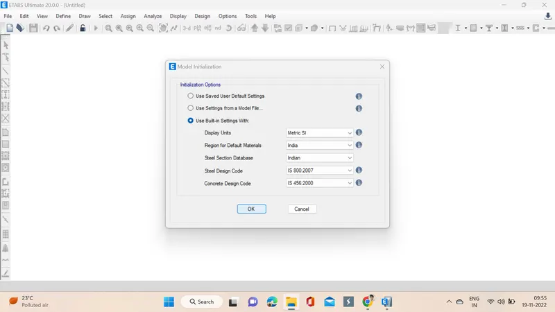
2. The very next step is to assign settings like codes used and units, then ok is clicked.
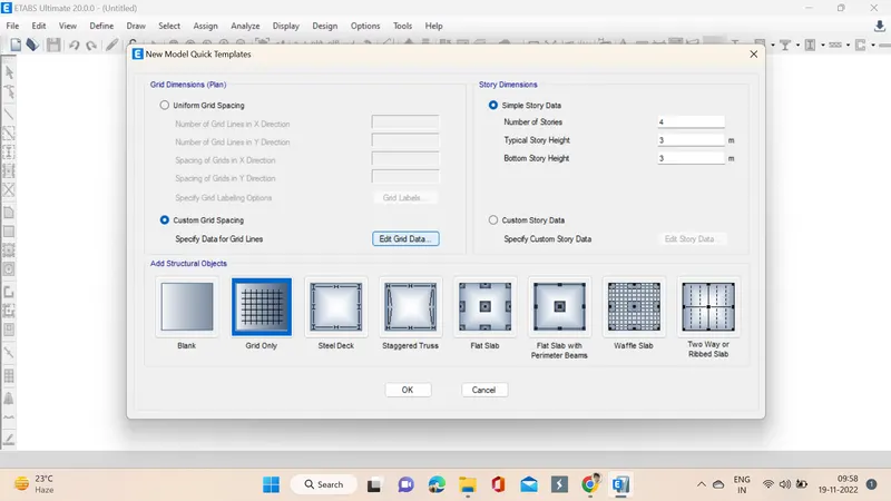
3. Now another tab pops up in which custom gird spacing is selected and edit grid data is opened.
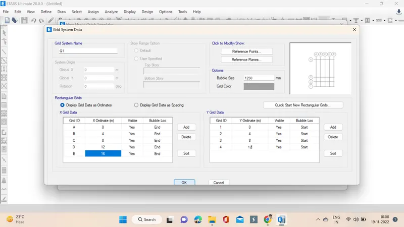
4. The x ordinate one more is added and the necessary changes are made even in y ordinate.
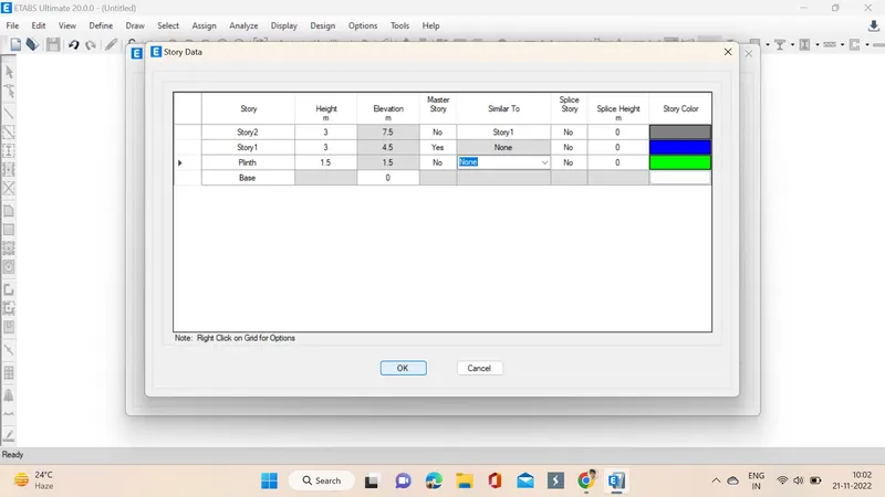
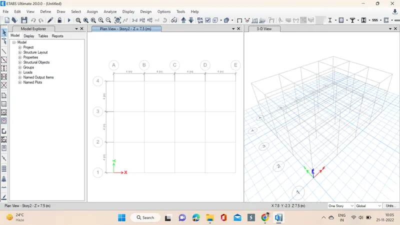
5. Next step we click on edit story data and then we change story 1 as plinth and then we specify the plinth height as 1.5 and change the names of stories accordingly, story1 is marked as master story. The building created is shown below.
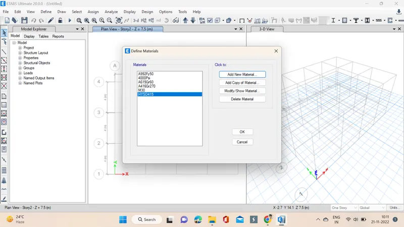
6. Go to define materials option, select material properties, in that concrete of M30 and reinforcement of 415 are added.
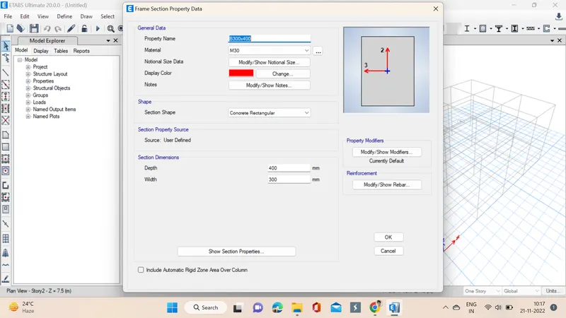
7. We need assign beams, columns for that go to define option -> frame sections. Beams as per the schedule is titled and dimensions are also specified, in the section properties beam is selected and material is given as M30 as assigned before and for rebar HYSD 415 is specified.
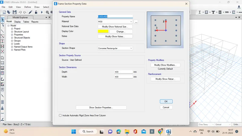
8. We need assign beams, columns for that go to define option -> frame sections. The process is same for columns assigning materials and dimensiopns but section properties column is selected that is the only change.
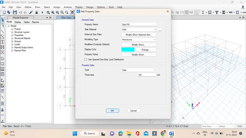
9. Next step we go through the define material and then select slab sections a window pops up in which we specify the properties of the slab and it is attached to the membrane.
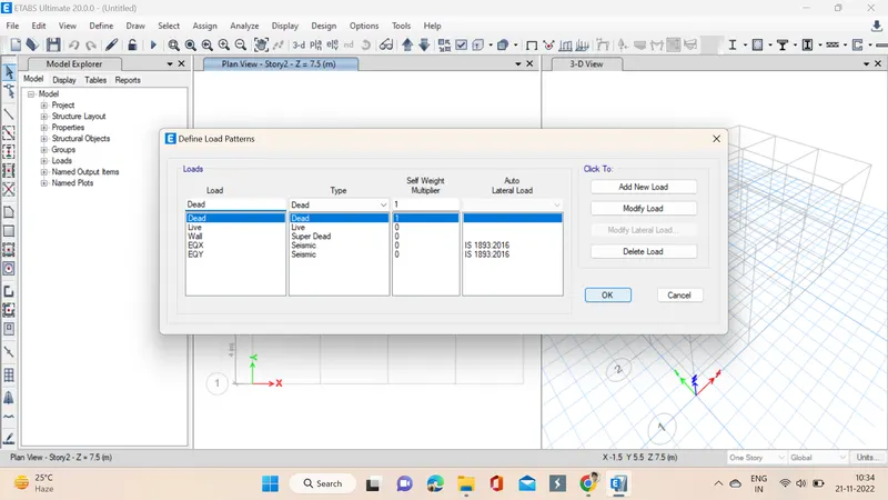
10. We assign loads in the following step from define option we select load patterns, as dead live were present additional loads are added.
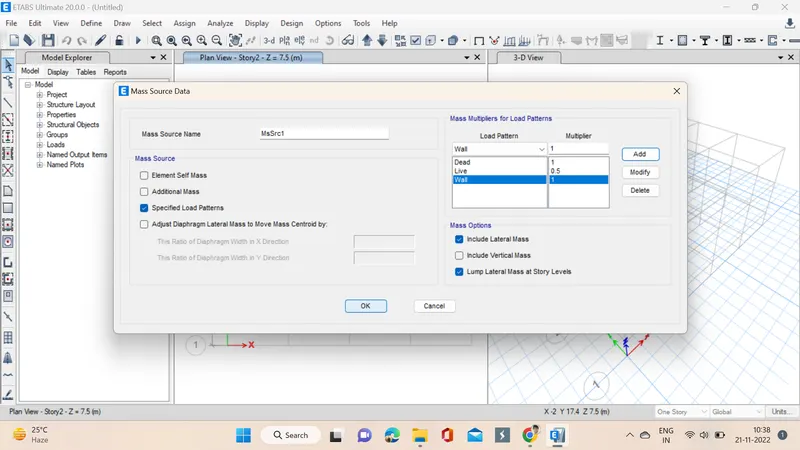
11. Now mass source is added by selecting mass source from define option, loads and values are specified and then ok is clicked to add.
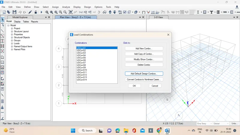
12. Now load cases are added or not checked by clicking on load cases, next load combinations are specified by selecting frame design user defined in load combinations.
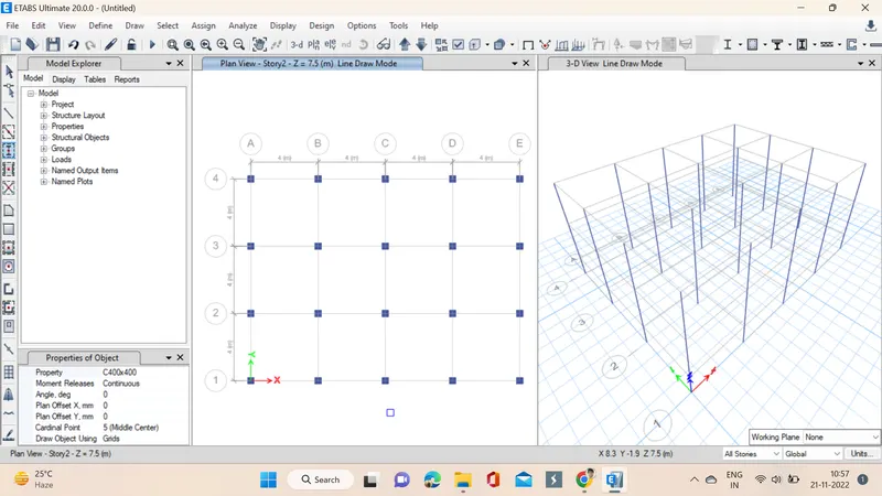
13. Now by selecting quick column and properties of specified column the columns are placed but we need to make sure the all stories option is selected. We can see the columns are specifed in all the stories, as we opted all stories option in the bottom right side. Next we use replicate option to simply replicate all the columns as first to save time.
14. Now by selecting quick beams and properties of specified beams the beams are placed but we need to make sure the all stories option is selected. We can see the beams are specifed in all the stories, as we opted all stories option in the bottom right side. Next we use replicate option to simply replicate all the columns as first to save time.
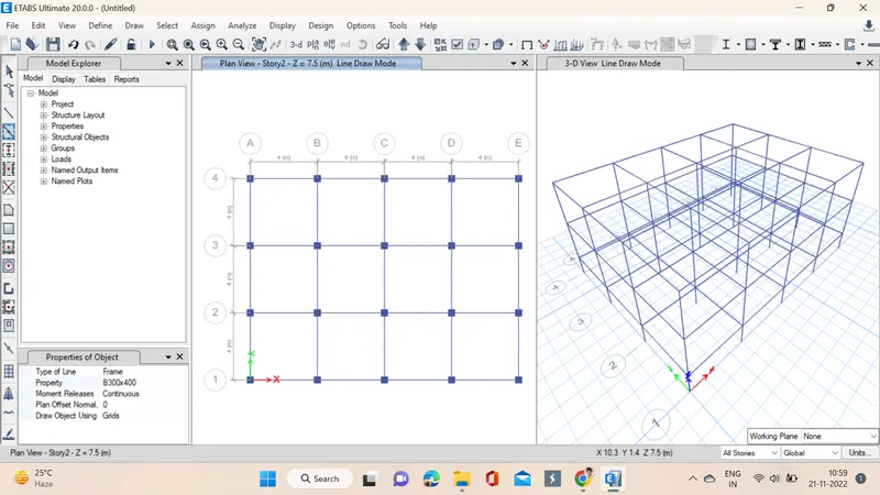
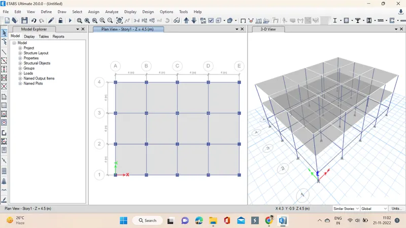
15. Now the slabs are placed by selecting quick draw slab, we need to select the specified slab and then drop them in the stories, before this we need to go to story1 from plan option and then select story1 after that we need to go to the similar stories option as we dont want slab at our plinth level.
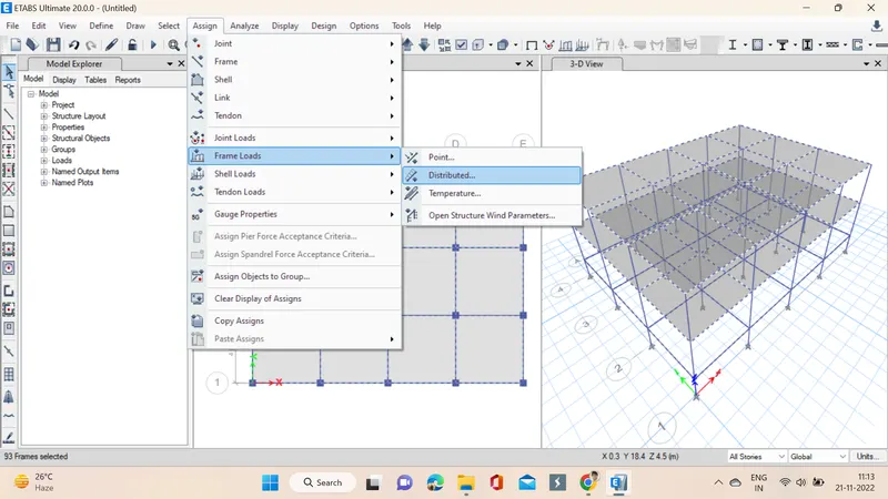
16. Now we will apply loads, for that first we select the beams from select option -> properties -> frame sections, after selecting the beams now load is assigned by going into assign option assign -> frame loads -> distributed in the distributed a window pops up in which load pattern is given as wall, load as 10KN/m as per the assignment and apply and okay is clicked.
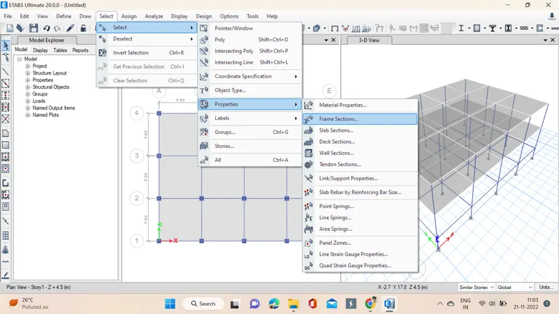
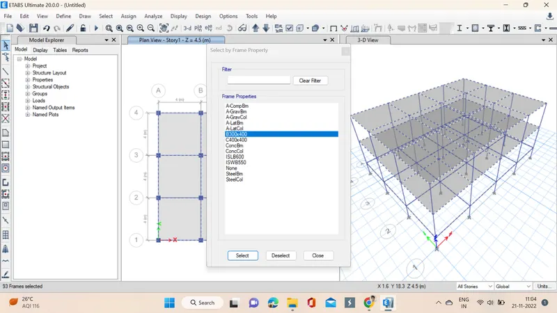
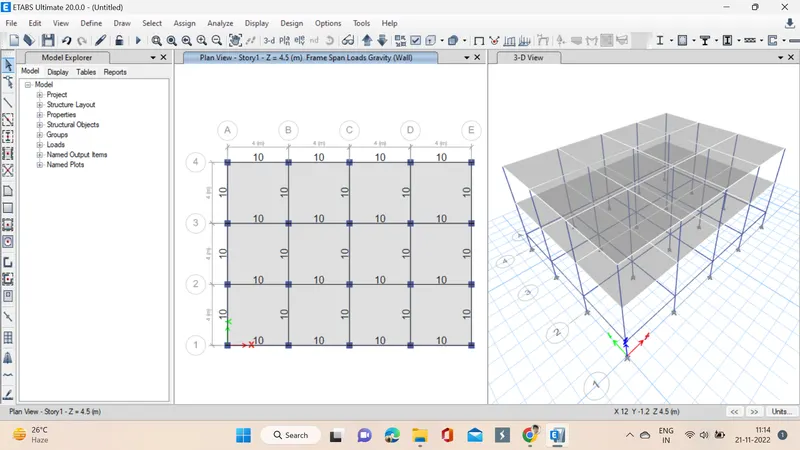
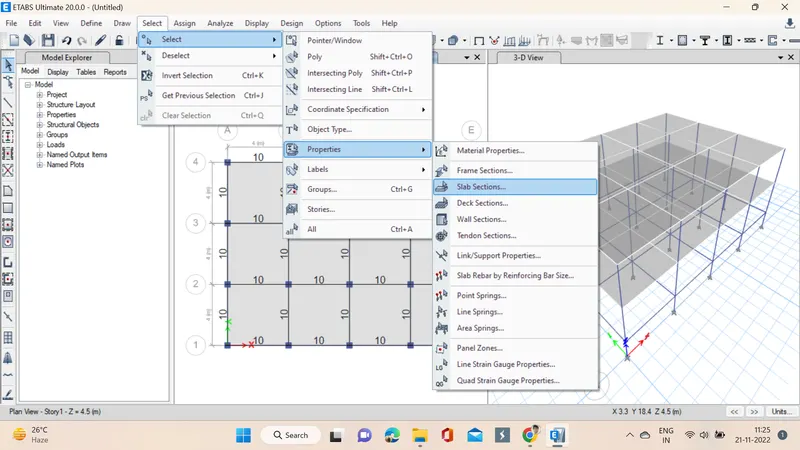
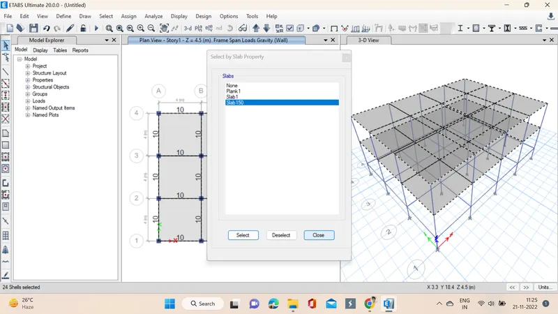
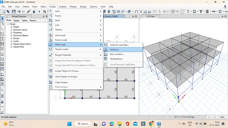
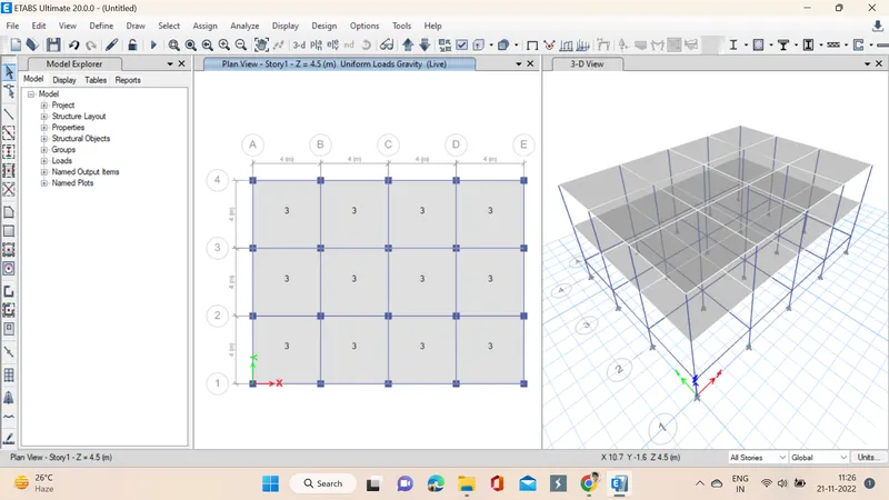
17. In the next step we select the slabs by same process now select option -> properties -> slab sections, after selecting the slabs now load is assigned by going into assign option assign -> shell loads -> uniform then a window pops up in which load pattern is given as live, load as 3KN/m^2 as per the assignment and apply and okay is clicked.
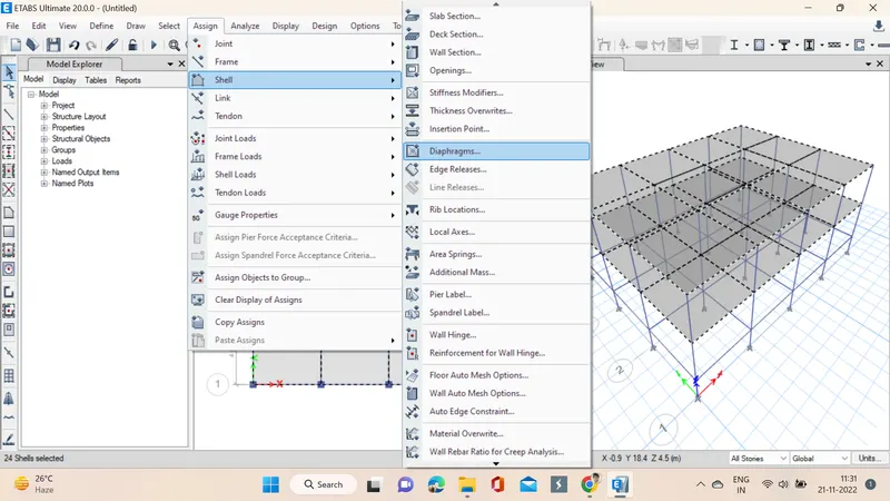
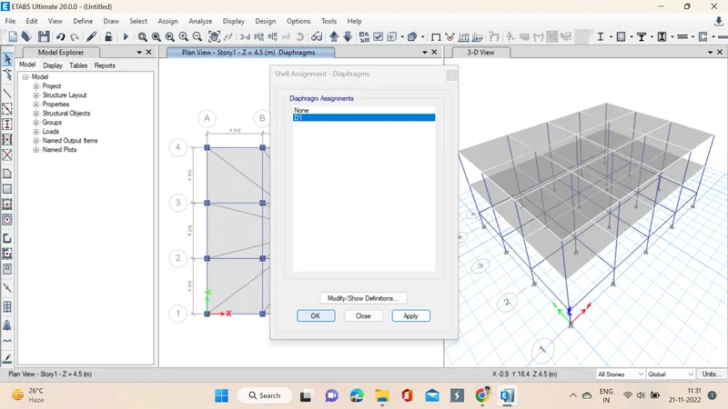
18. Again slabs are selected this time to assign diaphragms and then D1 is assigned so that the centre of mass will be calculated automatically.
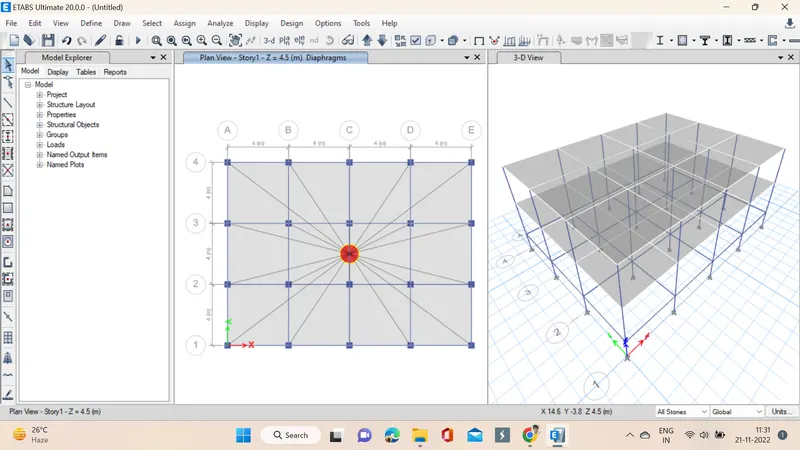
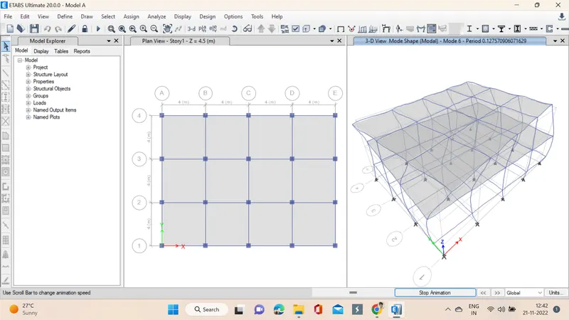
19. A 2 story building using the ETABS software was drawn and the loads are also assigned and analysis is runned successfully by saving it with a appropriate name Model A.
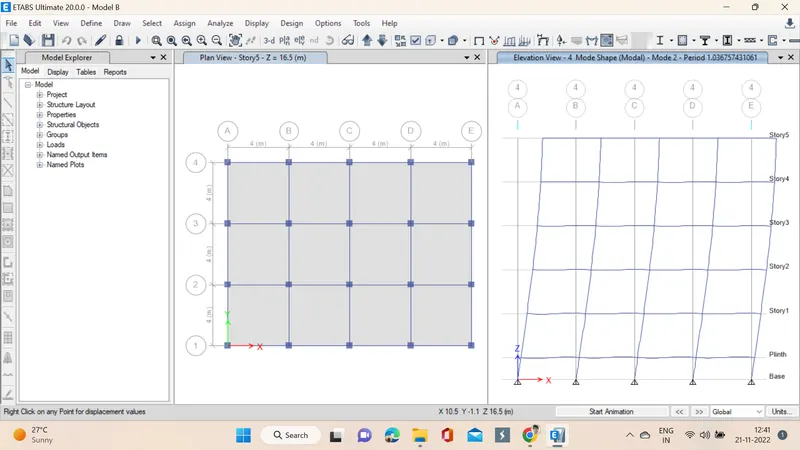
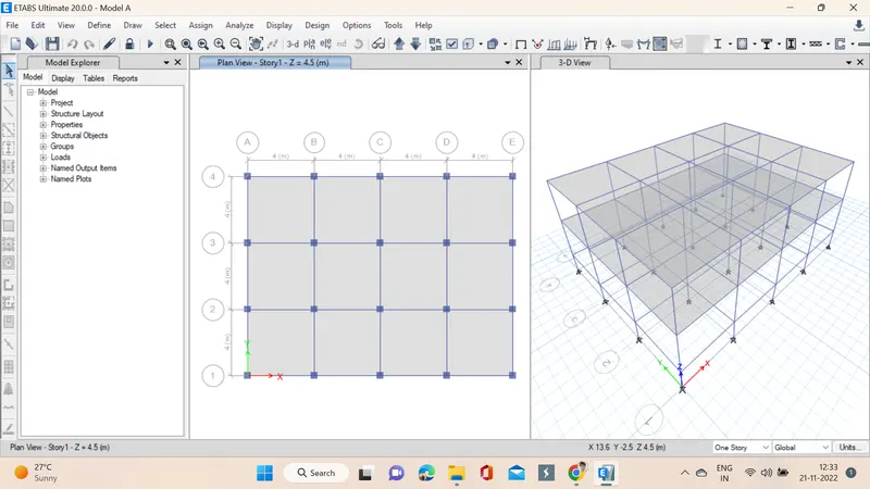
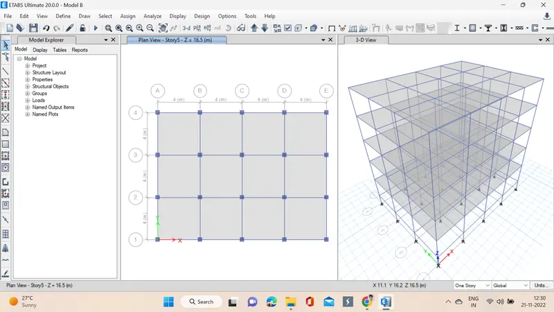
RESULTS: A Model A and Model B two building are created using ETABS software and the following studies are made:
Model A Model B
Factors influencing the dynamic characteristics of a building:
Buildings oscillate during earthquake shaking. The oscillation causes inertia force to be induced in the building. The intensity and duration of oscillation, and the amount of inertia force induced in a building depend on features of buildings, called their dynamic characteristics, in addition to the characteristics of the earthquake shaking (beyond the control of an engineer) itself. The important dynamic characteristics of buildings are modes of oscillation and damping (assumed constant in most practical cases). A mode of oscillation of a building is defined by associated Natural Period and Deformed Shape in which it oscillates. Every building has a number of natural frequencies (how many?), at which it offers minimum resistance to shaking induced by external effects (like earthquakes and wind) and internal effects (like motors fixed on it). Each of these natural frequencies and the associated deformation shape of a building constitute a Natural Mode of Oscillation. The mode of oscillation with the smallest natural frequency (and largest natural period) is called the Fundamental Mode; the associated natural period T1 is called the Fundamental Natural Period.
Factors influencing the Mode shape of oscillations:
- Effect of Flexural Stiffness of Structural Elements on mode shapes: Compare fundamental mode shape of Building B in two situations when flexural stiffness of beams relative to that of adjoining columns is very small versus when it is large.
- The lateral translational mode shapes depend on flexural stiffness of beams relative to the adjoining columns. The fundamental mode shape of buildings changes from flexural-type to shear-type as beam flexural stiffness increases relative to that of column
- When flexural stiffness of beams is small compared to that of the adjoining columns deformation is predominantly in single curvature bending leading to overall flexure-type deformation behavior of building.
- When flexural stiffness of beams is large compared to that of the adjoining columns, deformation is predominantly in double curvature bending within in each storey leading to overall shear-type deformation behavior of building
- But, increasing the flexural stiffness of a beam also increases its strength; this is not desirable when strengths of beams exceed that of columns into which they frame in, especially when beam strengths exceed those of the columns adjoining.
- Often in low-rise and mid-rise buildings that are designed as per codes, the relative stiffness of frame members lies in between the above two extreme cases. With the usual finite ratio of beam to column flexural stiffness, both beams and columns bend in double curvature and the response is almost of shear type. Thus, often, real buildings are idealized as shear buildings in structural analysis.