Project 1_Comparative study of different storey buildings for Seismic forces
Question:
Structural Element Sizes
- Beams : 300 × 400 mm
- Slab : 150 mm thick
Material Properties
- Grade of Concrete : M30
- Grade of Steel Reinforcement Bars : Fe 415
Loading
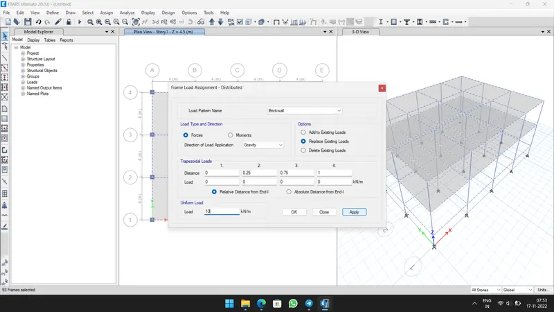
- Dead Load on beams from infill wall : 10 kN/m
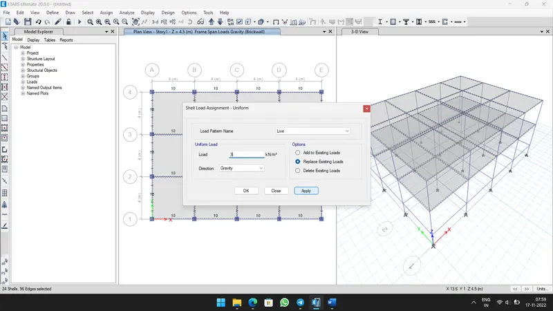
- Live load on floor : 3 kN/m2
(what is the seismic mass?)
Buildings are assumed to be pinned at base
Column and Storey to be reffered in the following Table.
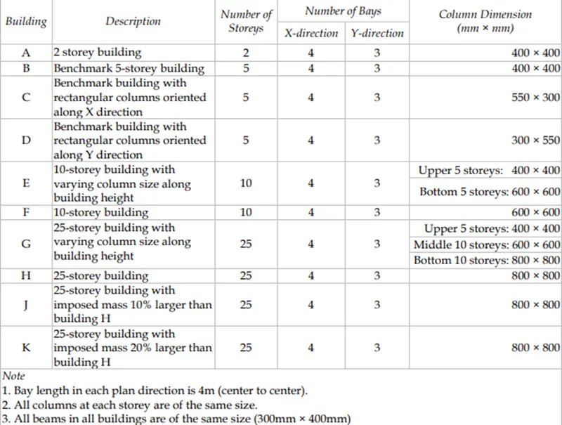
1) Factors influencing the dynamic characteristics of a building
2) Factors influencing the Natural Period of a building
3) Factors influencing the Mode shape of oscillations
Answer:
Aim:-
To compare the different buildings for factors influencing the dynamic characteristics, the Natural Period and the Mode shape of oscillations of a building.
Introduction:-
- Natural periods of buildings greatly affect the overall performance of buildings.
- To study this we are going to illustrate various types of buildings to study their dynamic characteristics of buildings by changing their column orientation, mass, and building height with the help of computational advanced analysis software ETABS.
Procedure:-
- Model a building with various sizes and Storeys.
Building A:
Step 1:-
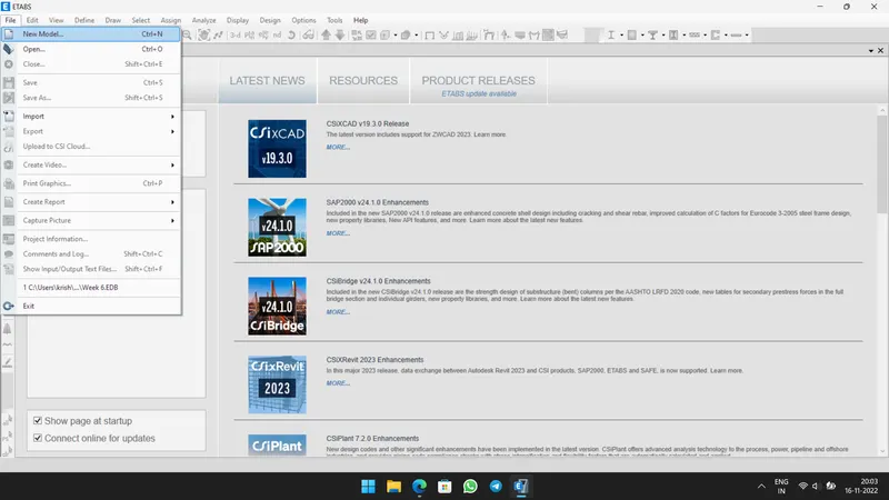
- Create a New Model from File Tab.
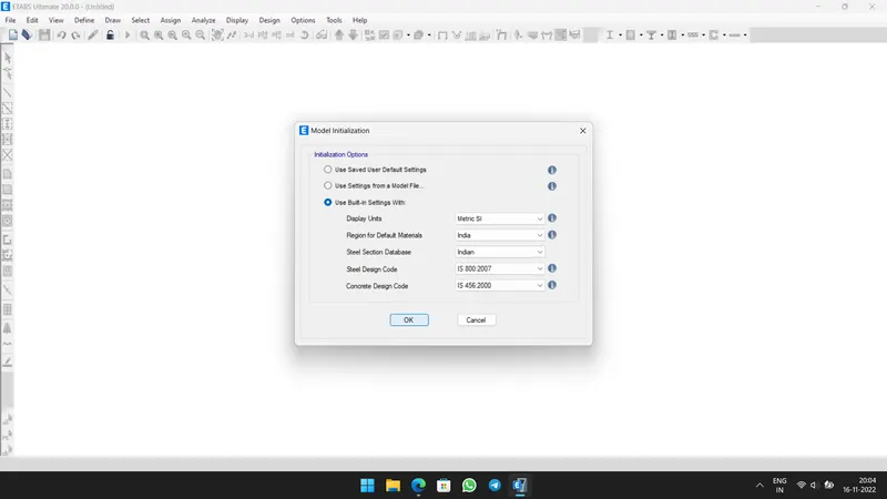
- Set details in Use Built in Settings with: as shown below.
- Set Grids in Custom Grid Spacing option.
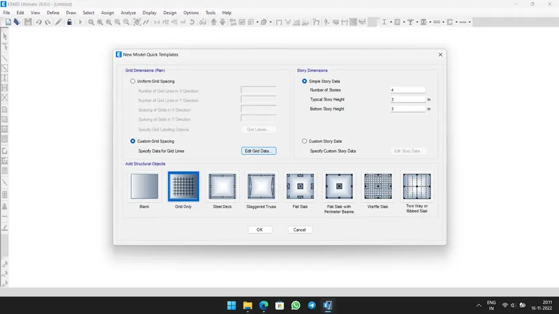
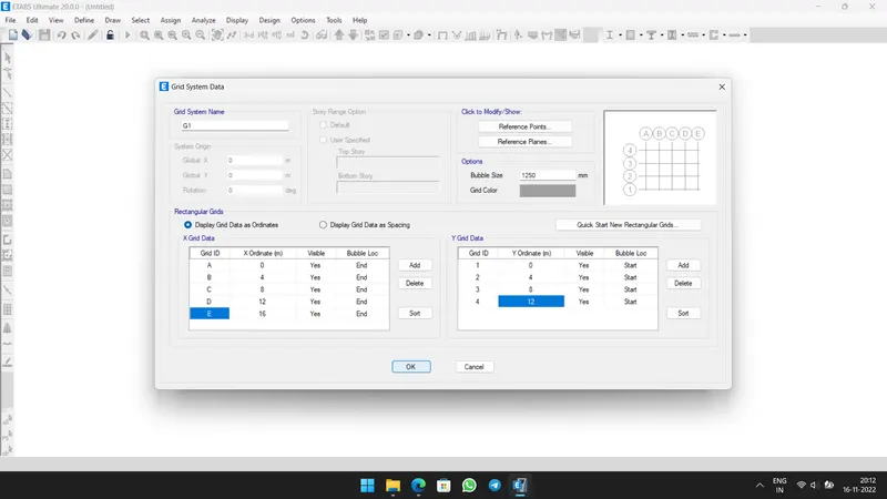
- Set Storeydetails in Custom Story Data option.
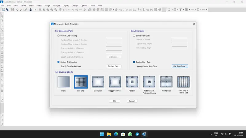
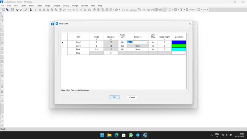
- Now Model generated in the window.
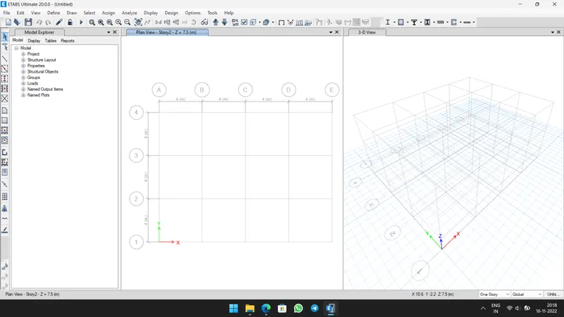
Step 2:-
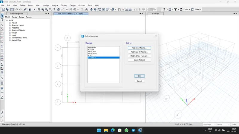
- Then define the Materials Properties from Define Tab.

- A New pop-up window opens, in that Click Add New Property.
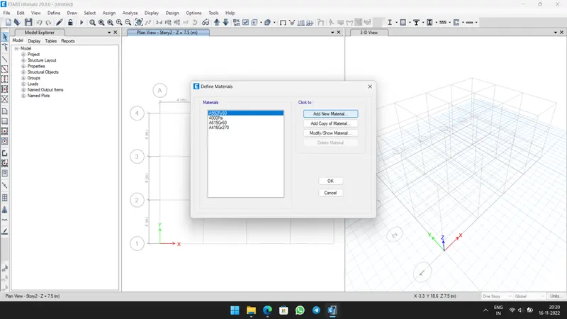
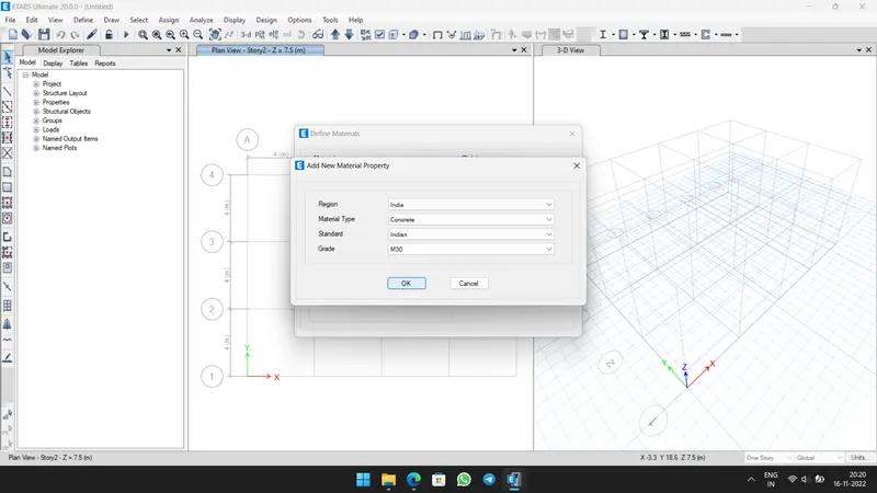
- Now Select Concrete material (M30) as shown below.
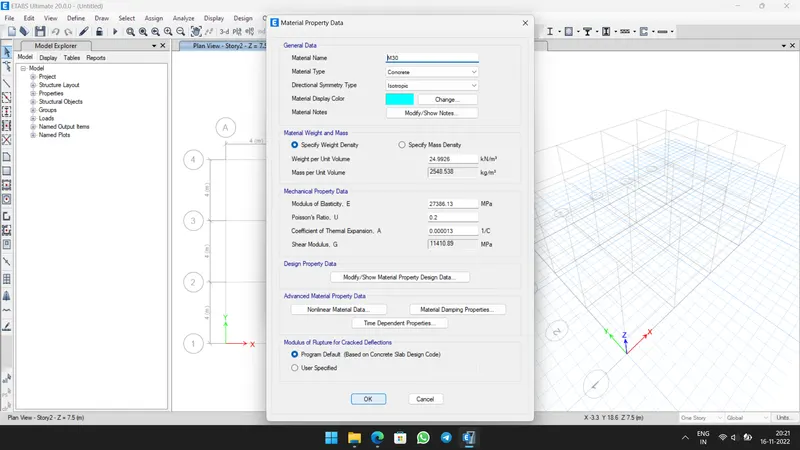
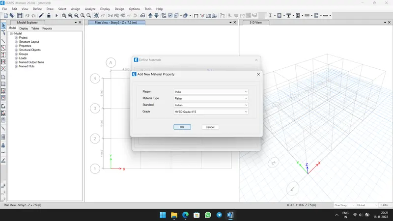
- Similarly, Define Rebar as Fe 415.
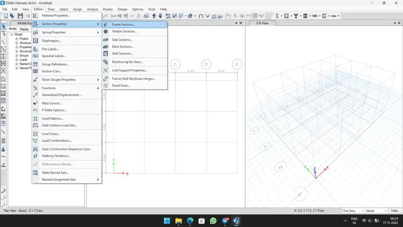
- Now Define Frame Section Properties from Define Tab.
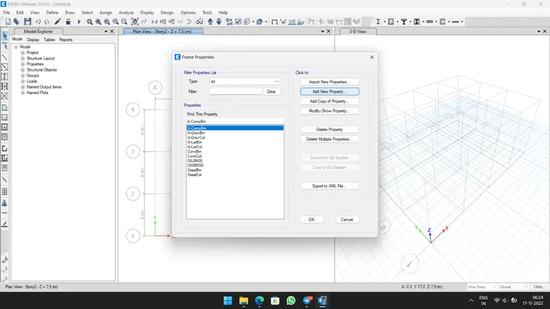
- A New pop-up window opens, then delete unwanted Properties and Click Add New Property.
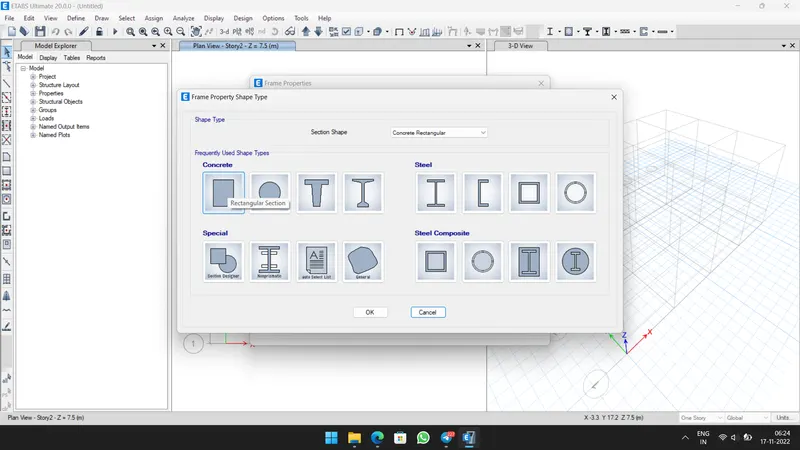
- Another window open, Rename the property as B300x400 and change the sizes.
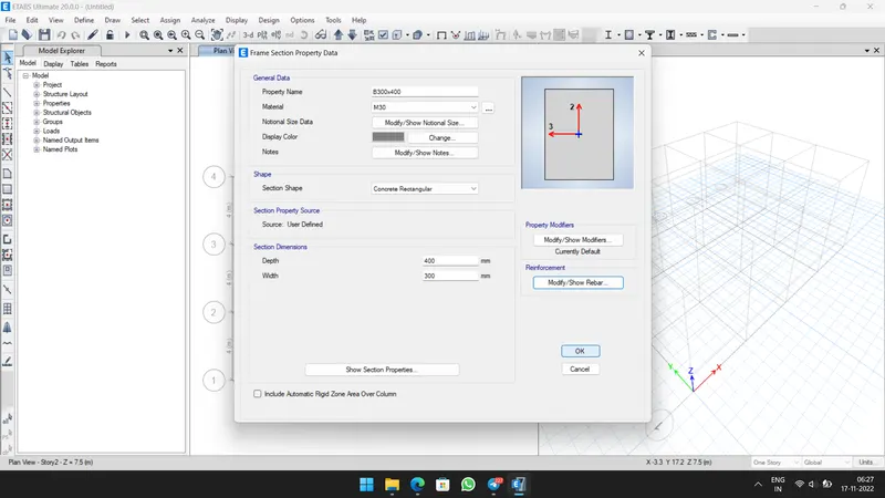
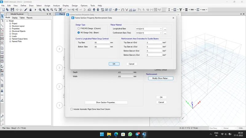
- Now Click Modidy/Show Rebar, then change Design Type as M3 Design Only (Beam) and change rebar proerty as Fe 415.
- Similarly define Column Property and name it as C400x400.
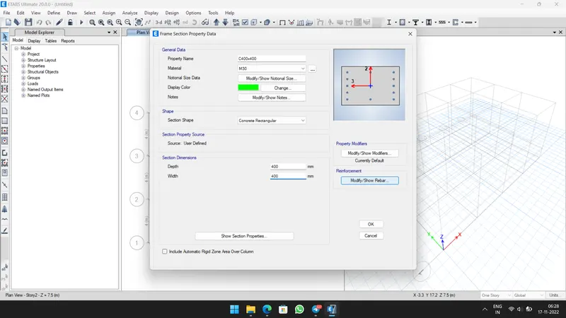
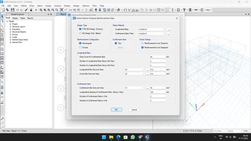
- Then select Slab section from Section Properties under Define Tab.
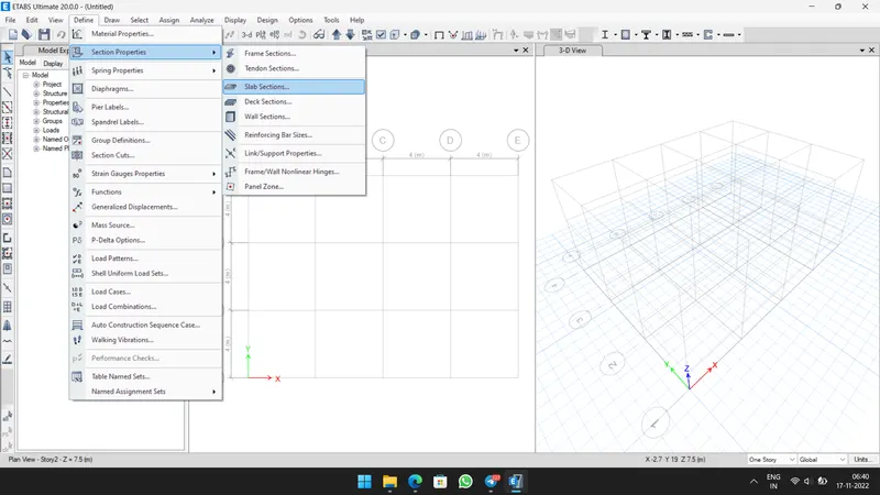
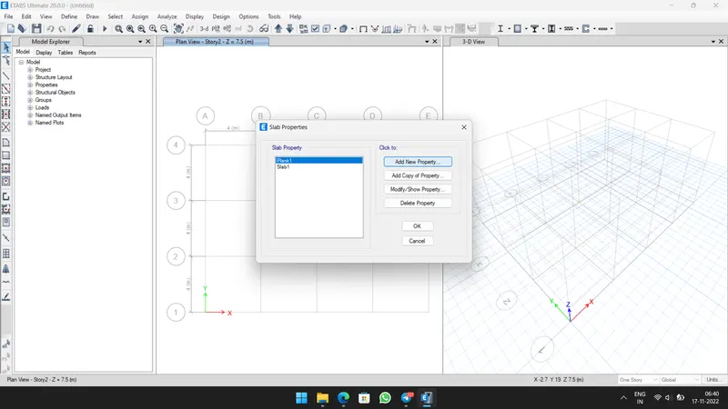
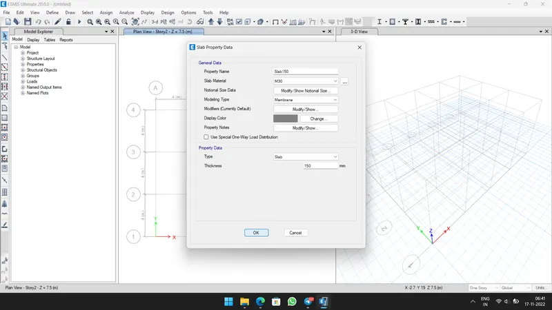
- A pop-up window appears, click Add New Property then rename the slab name as Slab150 and change Thickness as 150mm.
- Now select Loads Patterns under Define tab.
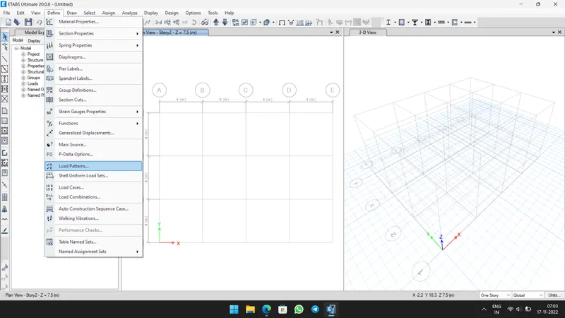
- Then define the Dead load, Live Load, Brickwall load and Earthquake load at both direction.
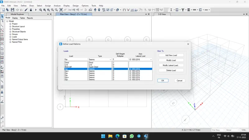
- Now Modify Lateral load as shown below.
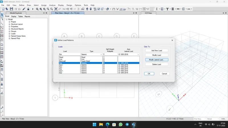
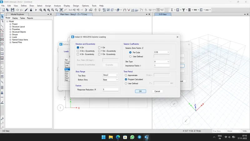
- Similarly modify all Earthquake loads.
- Then click Ok.
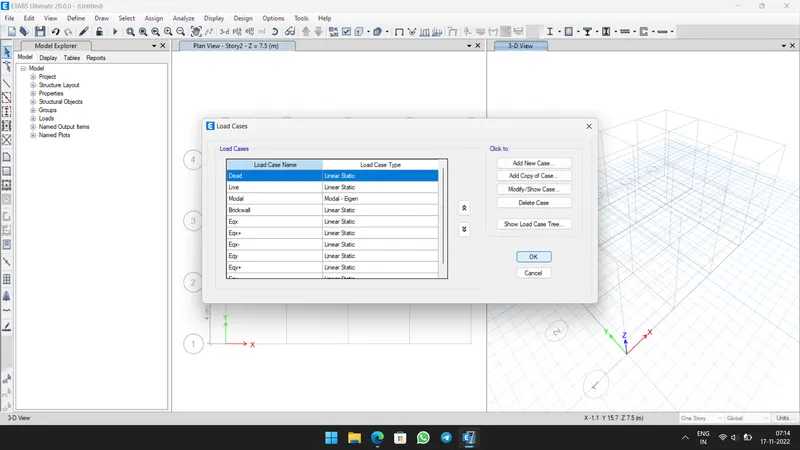
- Then Select Load cases under Define Tab.
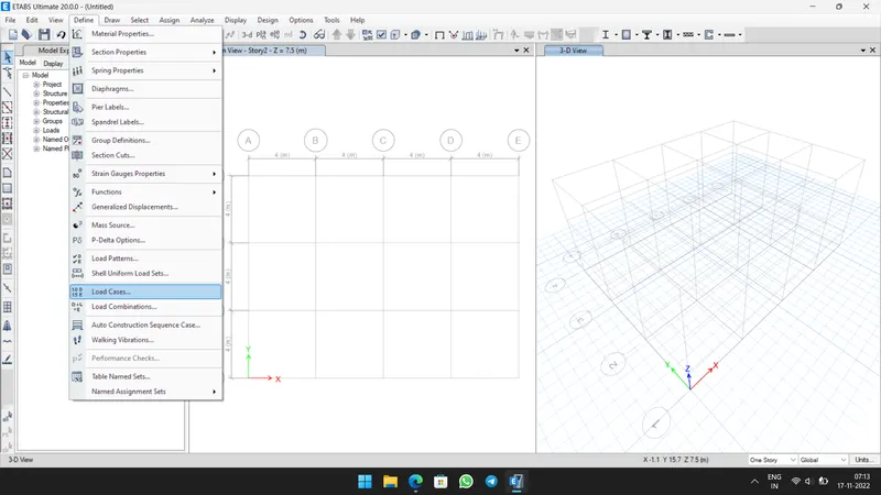
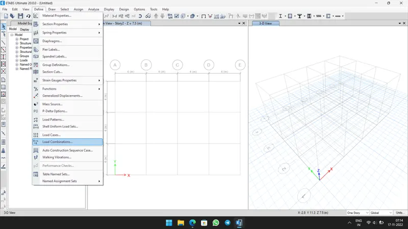
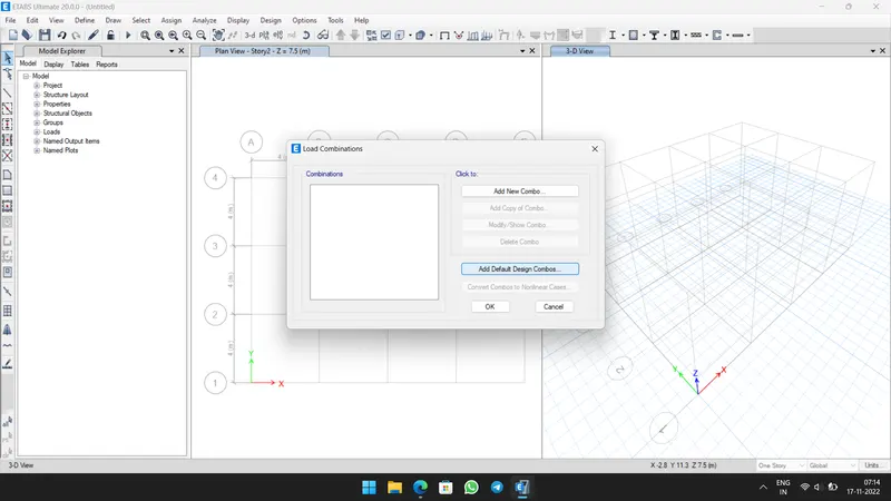
- Define Load combination, by Add Defualt Design combos.
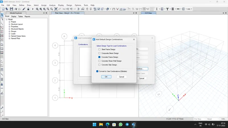
- Select Concrete Frame Design.
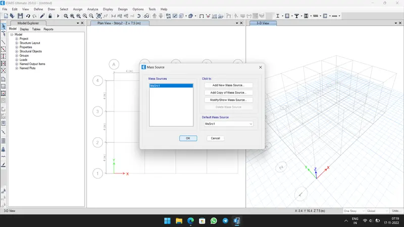
- Now Define Mass Sourse from Define Tab.
Step 3:-
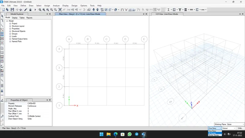
- First Set All Stories at the bottom of window.
- Then draw Column at each Grid joints by clicking Quick draw Column.
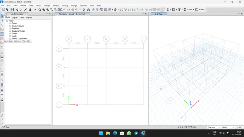
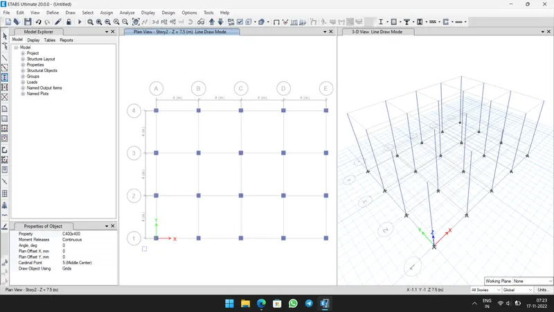
- Now Click Quick Draw Beams/Columns.
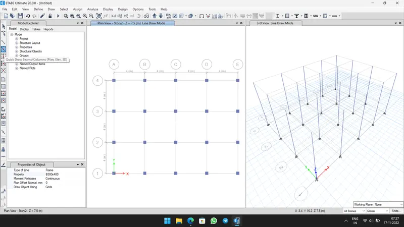
- Place the beam at all grids as shown below.
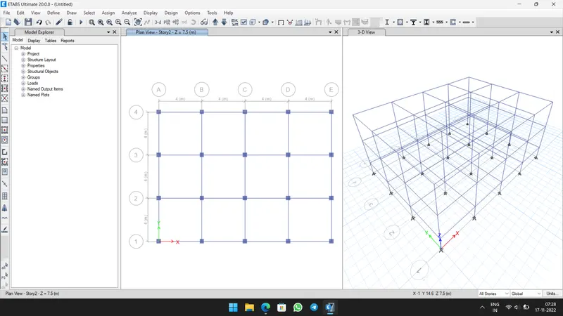
- Set Similar Stories at the bottom of window.
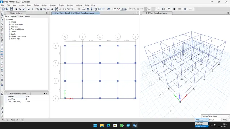
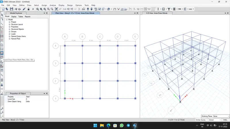
- Pick Quick Draw Floor/Slab, change the Property and Place the Slab at location.
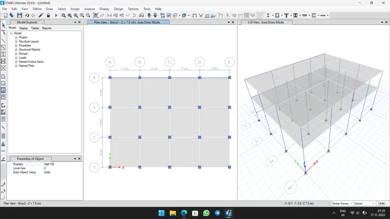
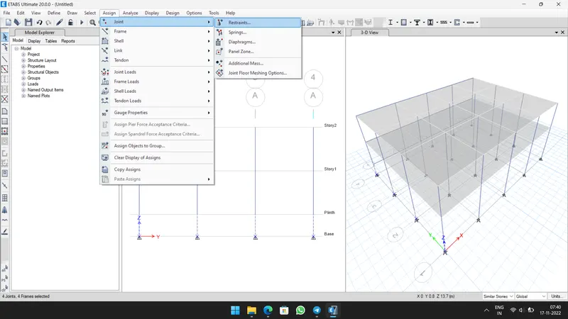
- Open Elevation view, Select all base supports.
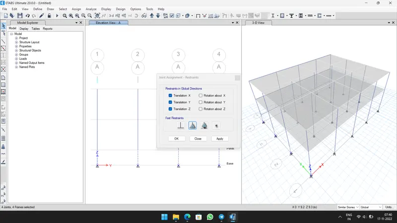
- Now go to Assign tab -> Joints -> Restraints.
- Then select Pinned base and click apply.
Step 4:-
- Assign Loads to the structural frame members.
- Set All Stories at the bottom of window.
- Select the all beams by click Object Type under Select Tab.
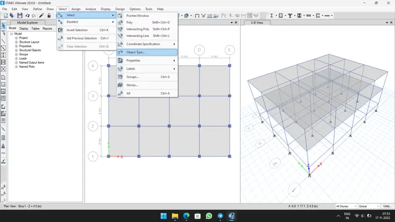
- Go to Assign tab -> Frame Loads -> Distributed.
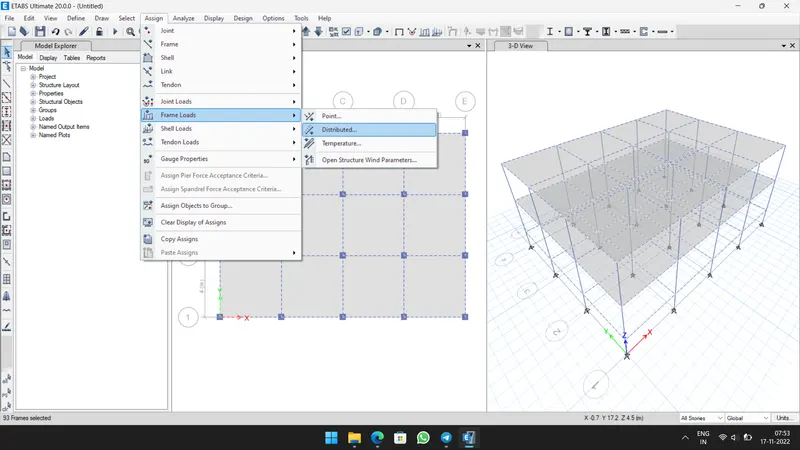
- A new pop-up window opens in that give Brickwall load of 10kN/m.
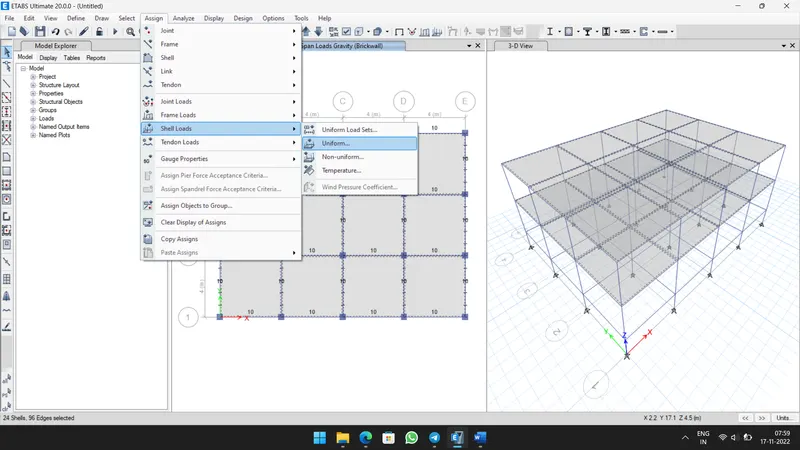
- Select all Slabs and Go to Assign -> Shell Loads ->Uniform.
- A new pop-up window opens in that give Live load of 3kN/m2.
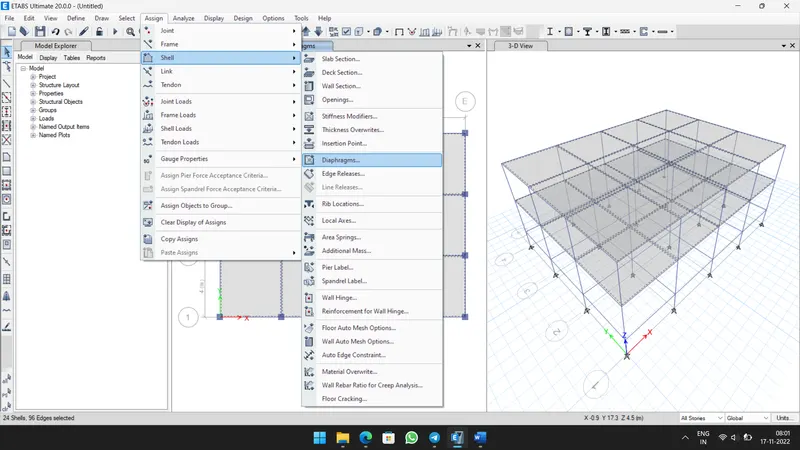
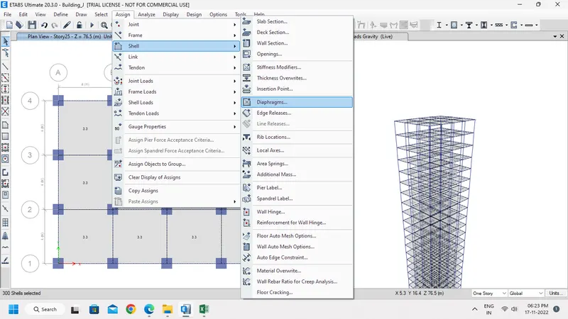
- Select all Slabs and Go to Assign -> Shell ->Diaphragm.
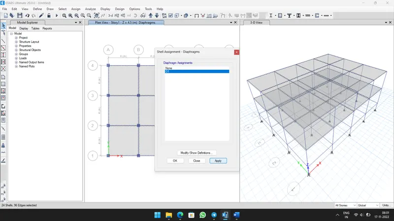
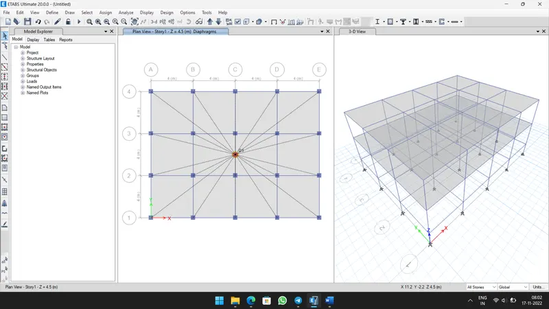
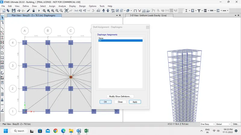
- A new pop-up window opens in that give Diaphragm as D1.
Step 5:-
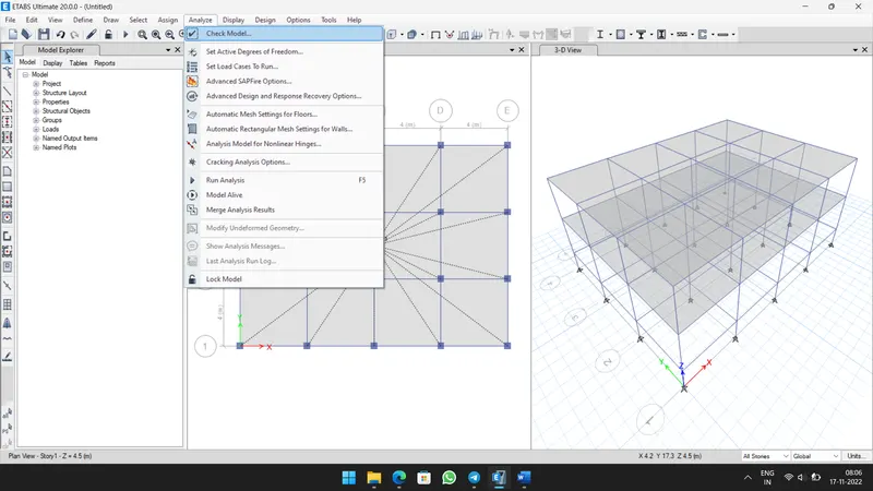
- Select Analyze Tab, then Check Model.
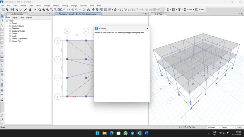
- Now click Run Analysis.
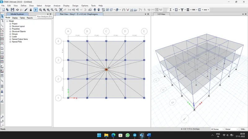
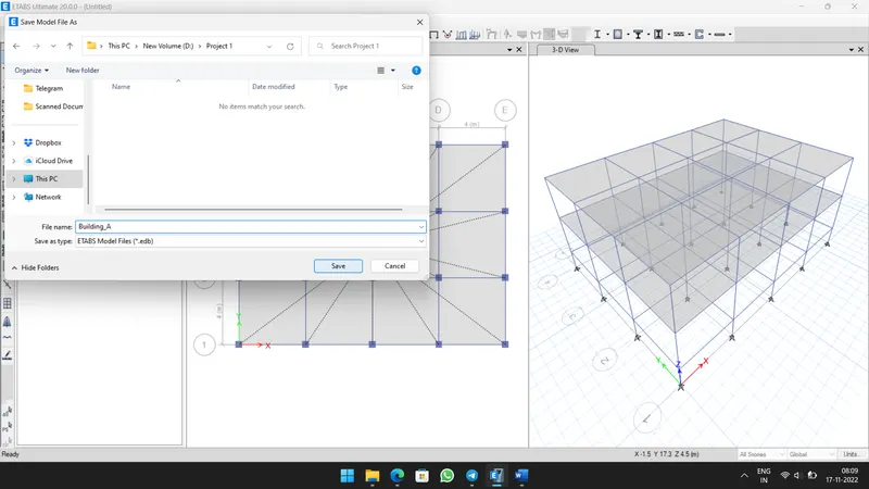
- To Run, Save the file at its appropriate location and name as Building_A.
- Now we can see the Building model deformed.
Building B:
Step 1:-
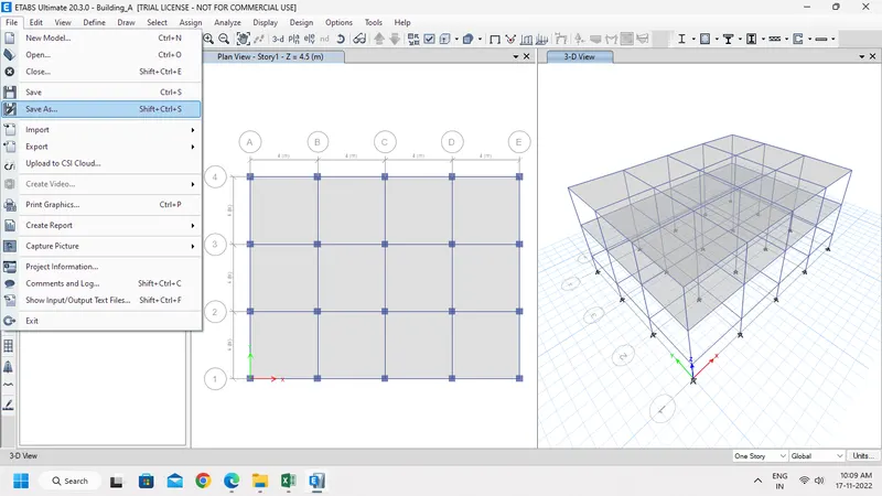
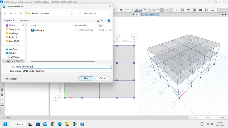
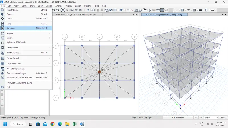
- In File Tab select Save as option to Save Building A as Building B.
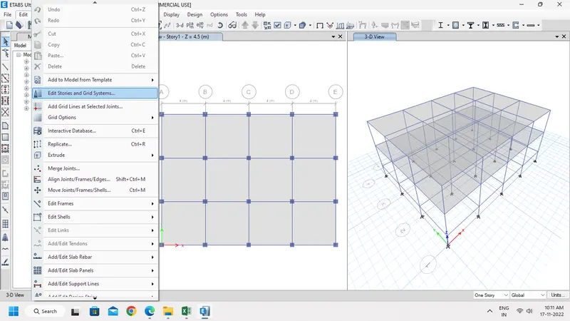
- In Edit Tab, selcet Edit Stories and Grid Systems.
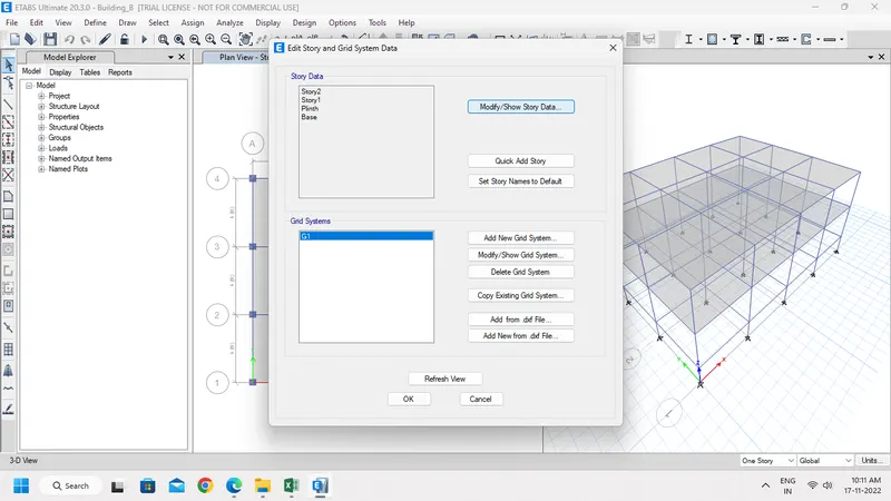
- A New pop-up window opens, in that Click Modify/Show Story Data.
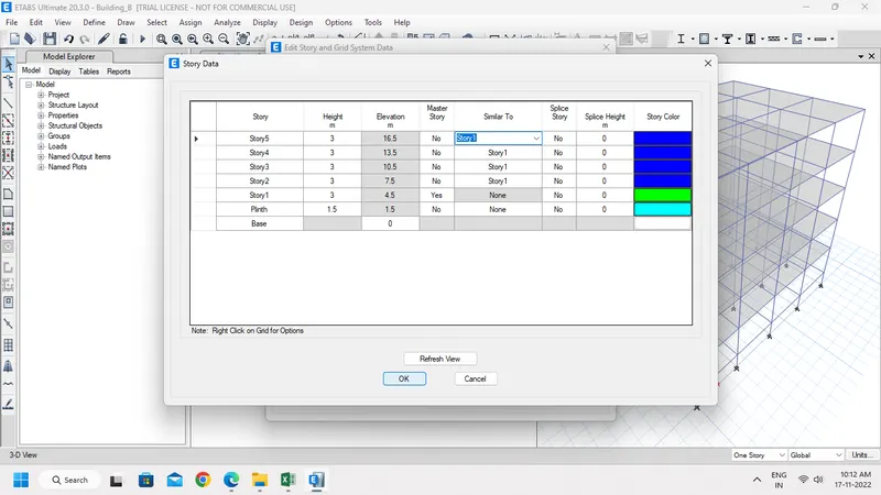
- Now add three more stories above Story 2 of height 3m each.
- And set Similar to Story 1.
Step 2:-
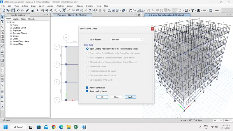
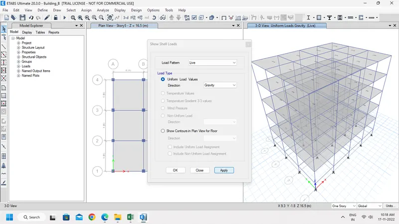
- Now check whether all loads applied to the model.
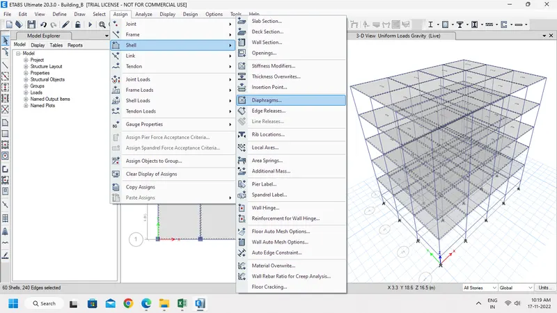
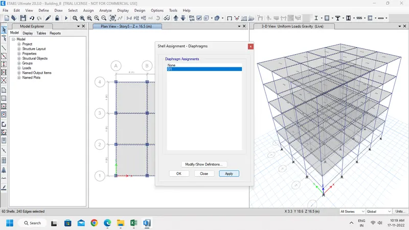
- Select all Slabs and Assign Diaphragm from Shell Option under Assign Tab.
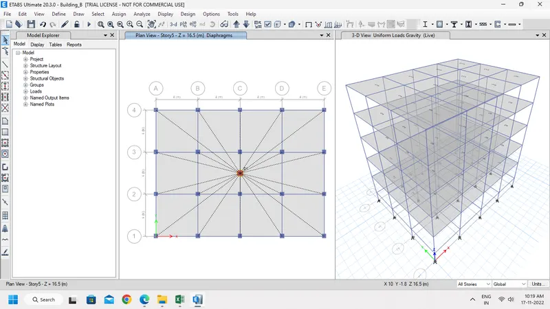
Step 3:-
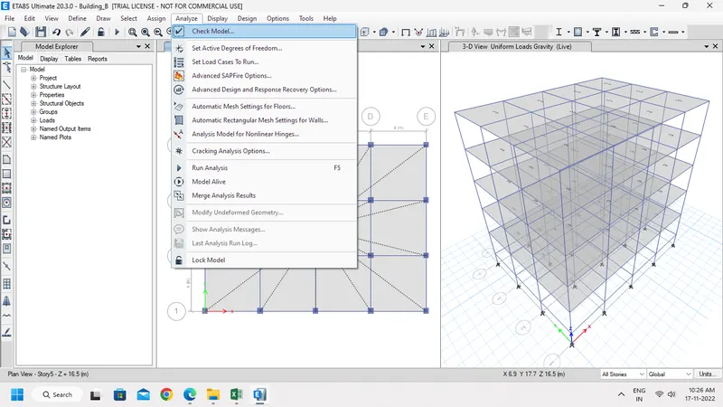
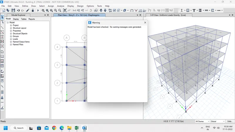
- Select Analyze Tab, then Check Model.
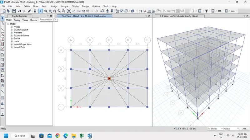
- Now click Run Analysis.
- Now we can see the model deformed.
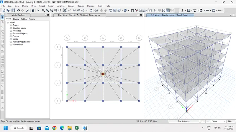
- Now save the file.
Building C:
Step 1:-
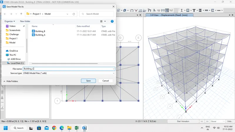
- In File Tab select Save as option to Save Building B as Building C.
Step 2:-
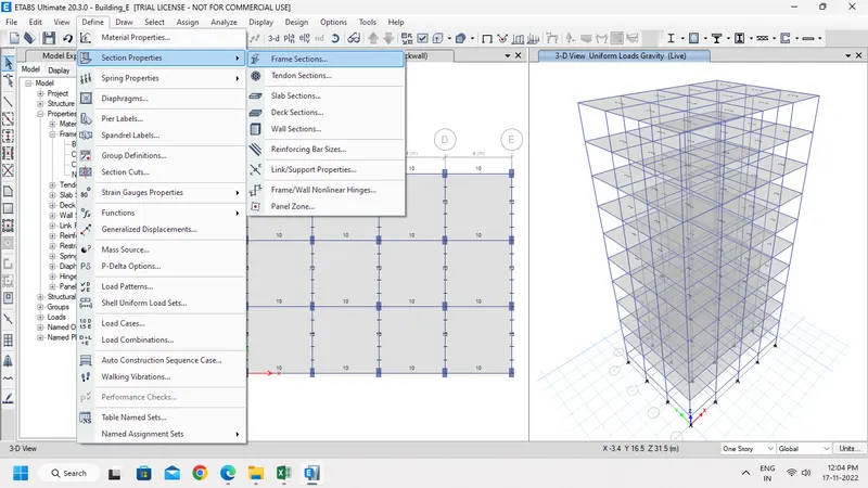
- In Define Tab, select Section Properties and click Frame sections.
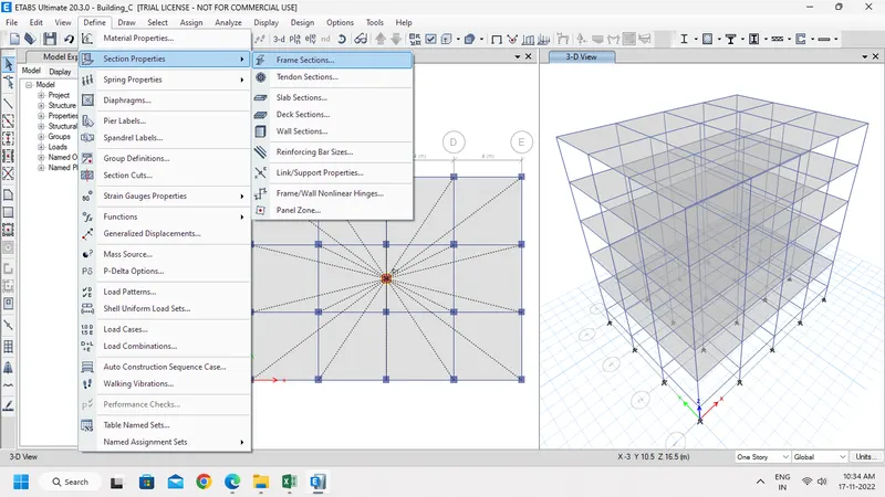
- A new pop-up window appears, add New property.
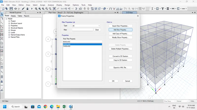
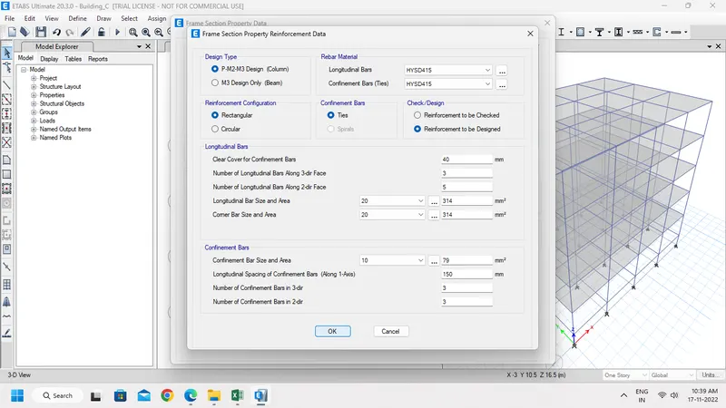
- And Rename it as C550x300 and change depth as 300mm and width as 550mm.
Step 3:-
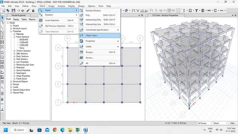
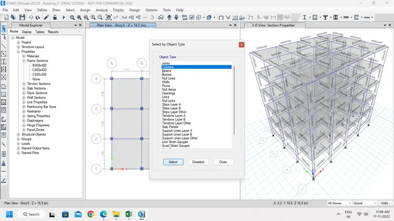
- Go to Select Tab, and choose Object Type. Then select all Columns.
- In Model explorer, click Frame sections and select C550x300.
- Then Right Click to Assign C550x300 to the selected columns.
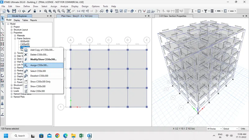
- Now Refresh the page to reflect the changes.
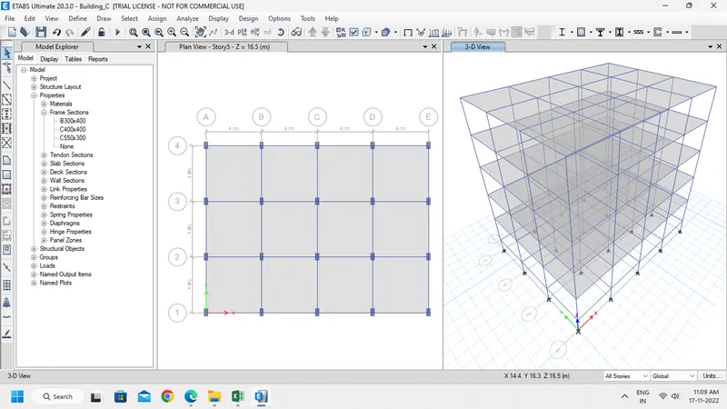
- Major Axis of columns along Y-Direction, so change the Column axis from Assign Tab.
- Select all columns from Select Tab.
- Go to Assign -> Frames -> Local Axes.
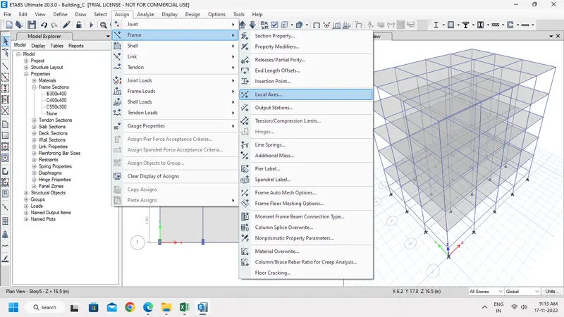
- A New Pop-up window appears, now change angle as 90 degree.
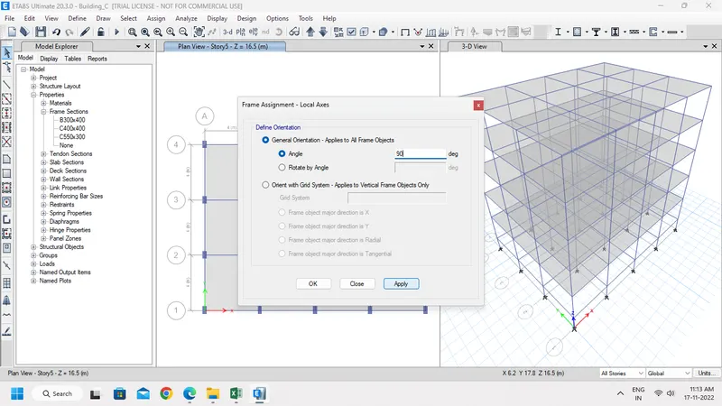
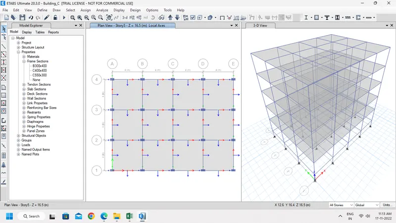
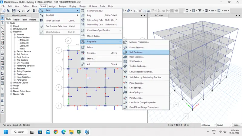
- Select all Slab from Select Tab.
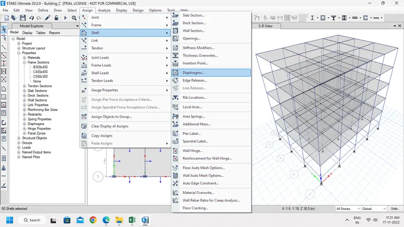
- Assign Diaphragm from Shell Option under Assign Tab.
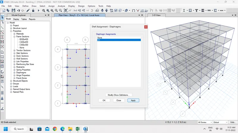
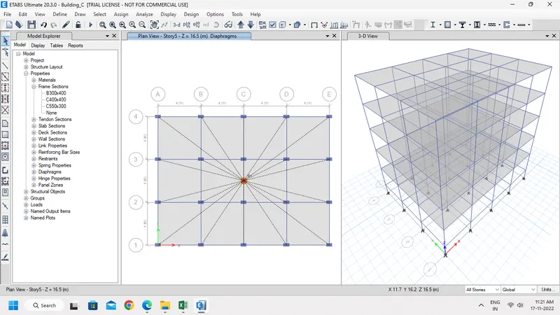
Step 4:-
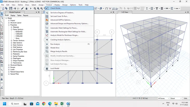
- Select Analyze Tab, then Check Model.
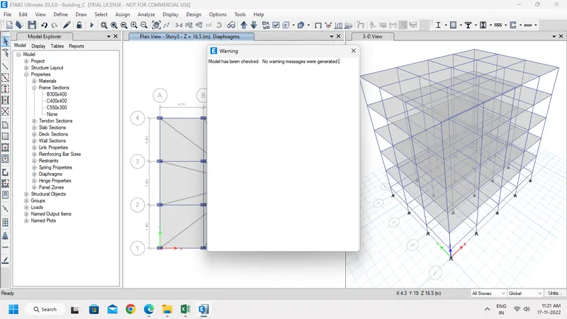
- Now click Run Analysis.
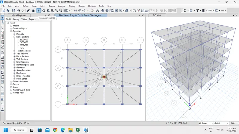
- Now we can see the model deformed.
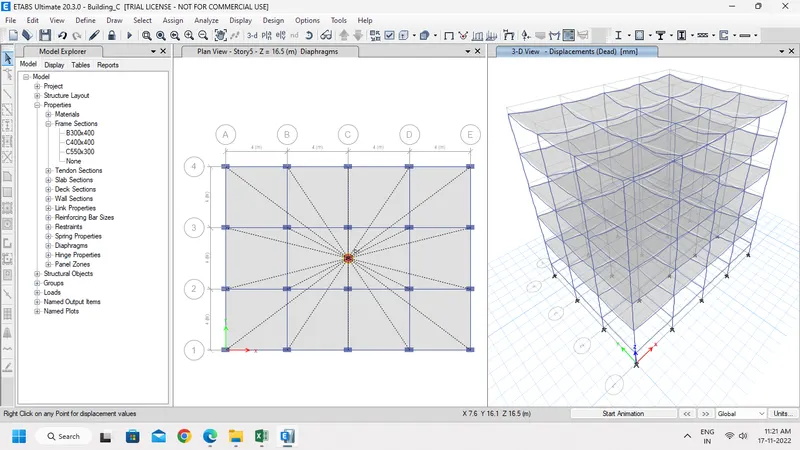
- Now save the file.
Building D:
Step 1:-
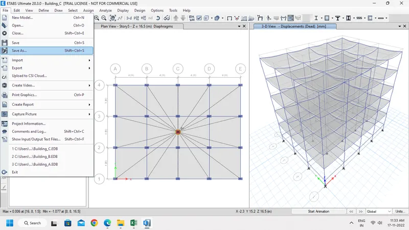
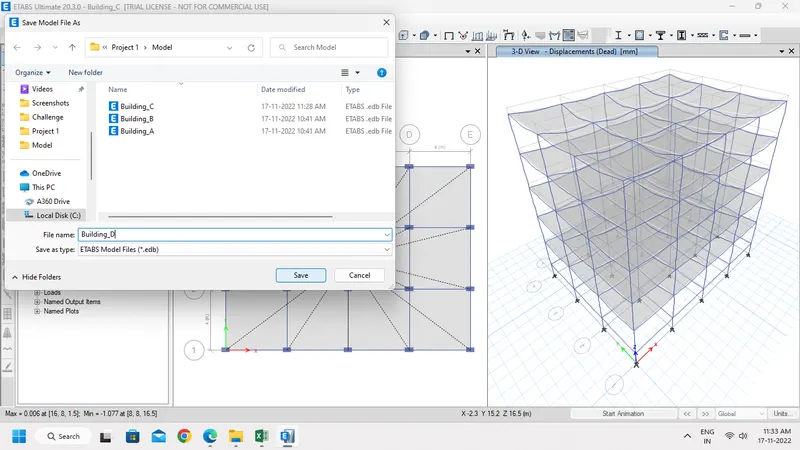
- In File Tab select Save as option to Save Building C as Building D.
Step 2:-
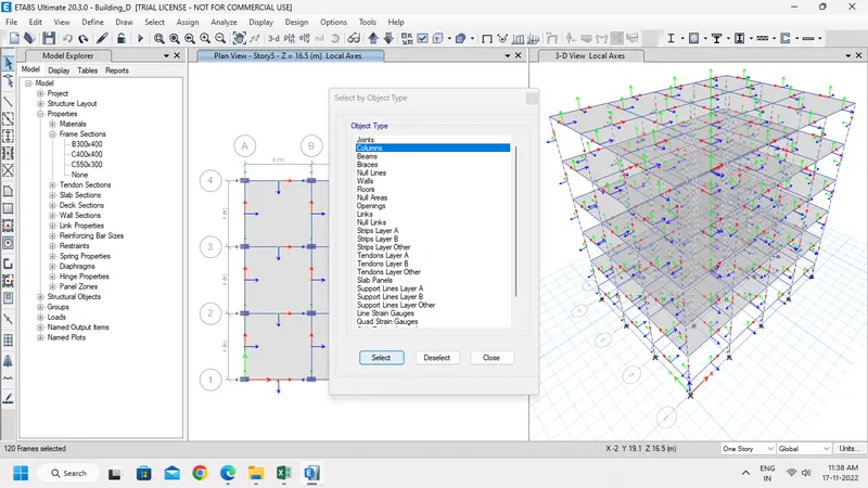
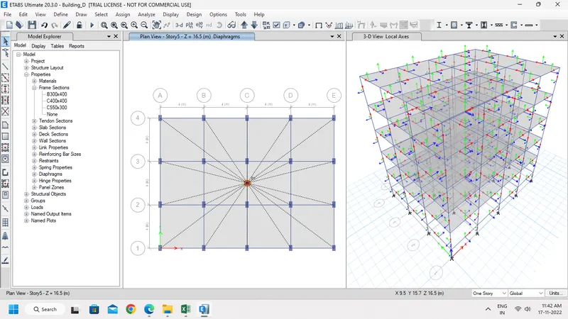
- Go to Select Tab, and choose Object Type. Then select all Columns.
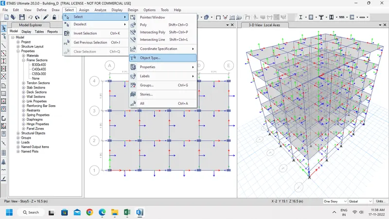
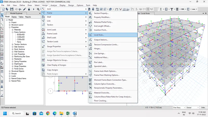
- Go to Assign -> Frames -> Local Axes.
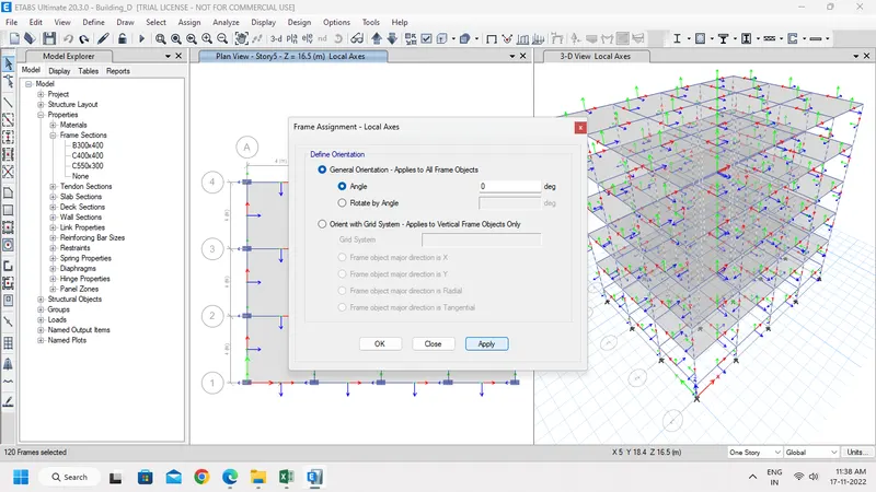
- A New Pop-up window appears, now again change angle to 0 degree.
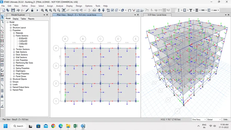
- Select all Slab from Select Tab.
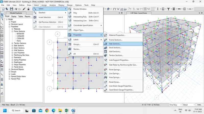
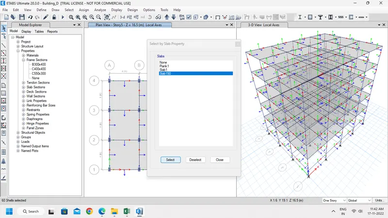
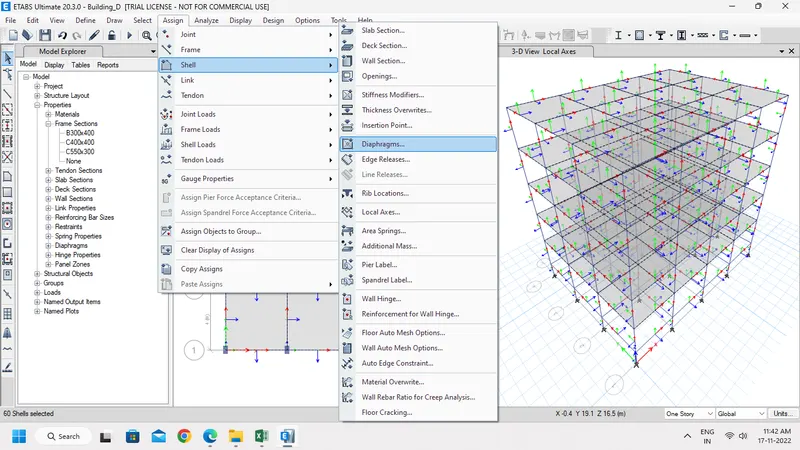
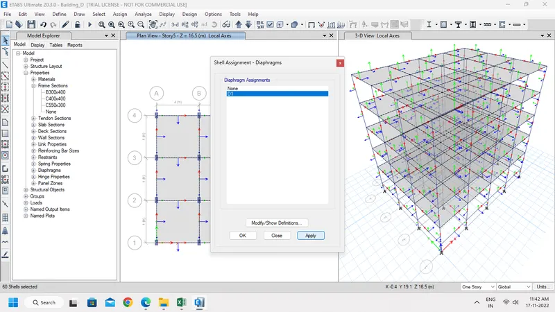
- Assign Diaphragm from Shell Option under Assign Tab.
Step 3:-
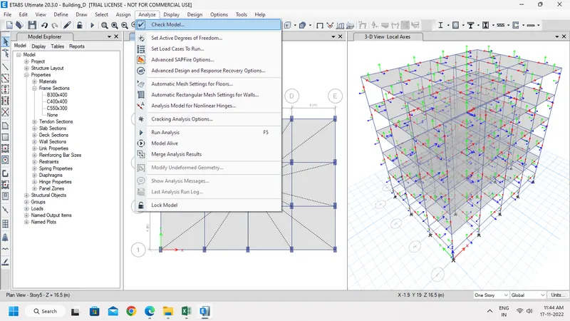
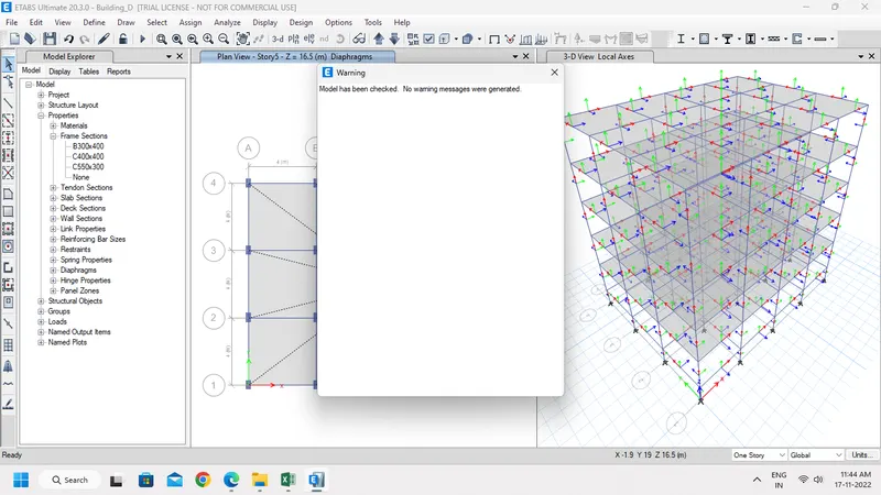
- Select Analyze Tab, then Check Model.
- Now click Run Analysis.
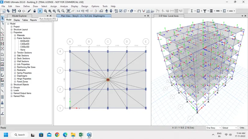
- Now we can see the model deformed.
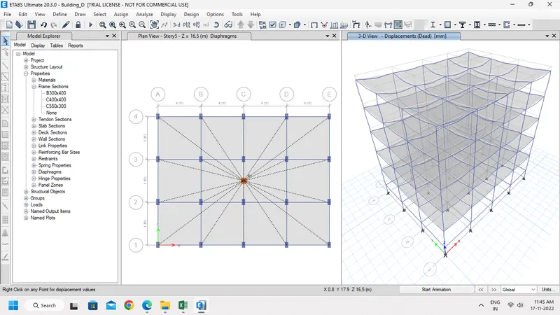
- Now save the file.
Building E:
Step 1:-
- In File Tab select Save as option to Save Building D as Building E.
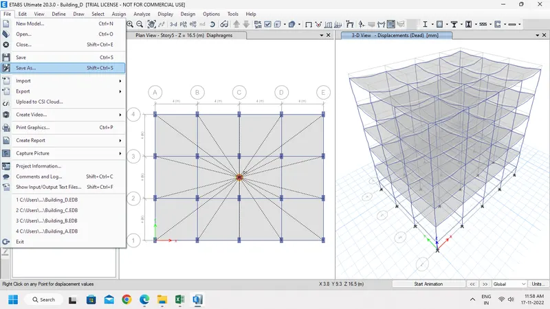
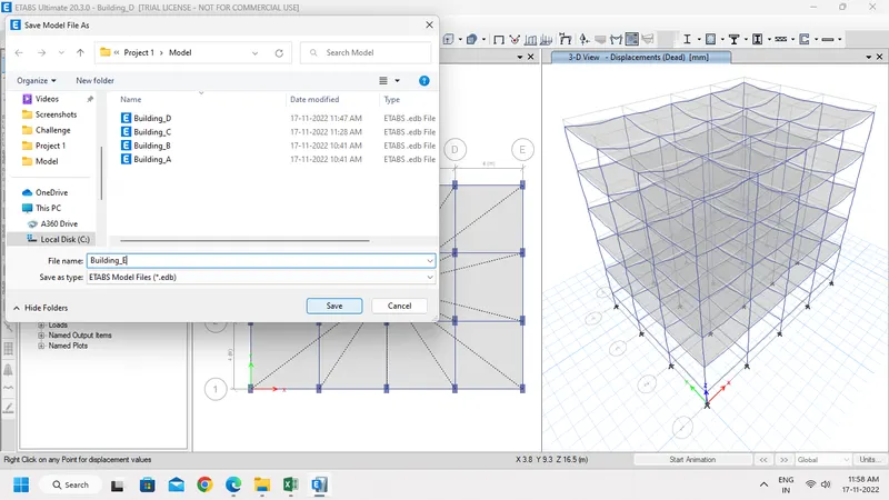
- In Edit Tab, selcet Edit Stories and Grid Systems.
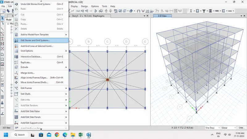
- A New pop-up window opens, in that Click Modify/Show Story Data.
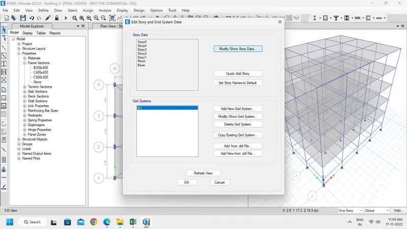
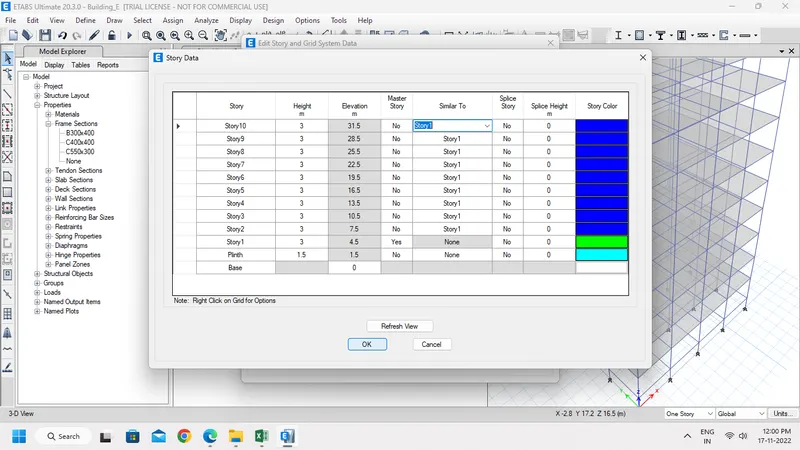
- Now add Five more stories above Story 5 of height 3m each.
- And set Similar to Story 1.
Step 2:-
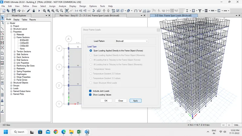
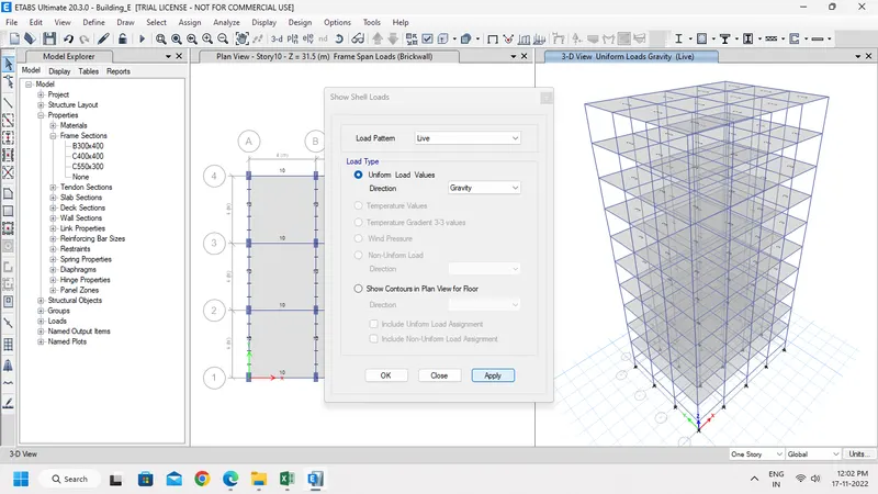
- Now check whether all loads applied to the model.
Step 3:-
- In Define Tab, select Frame Sections.
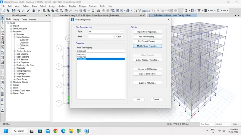
- A new pop-up window opens, in that Select C550x300 and click Modify/Show Property.
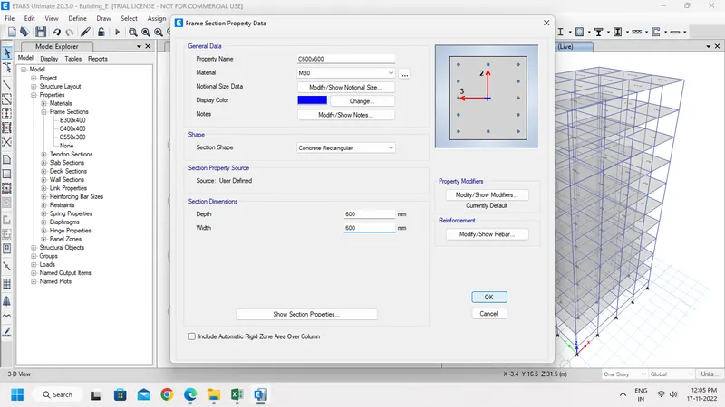
- Rename as C600x600 and Change Depth as 600mm and Width as 600mm.
Step 4:-
- Go to Set Display Option.
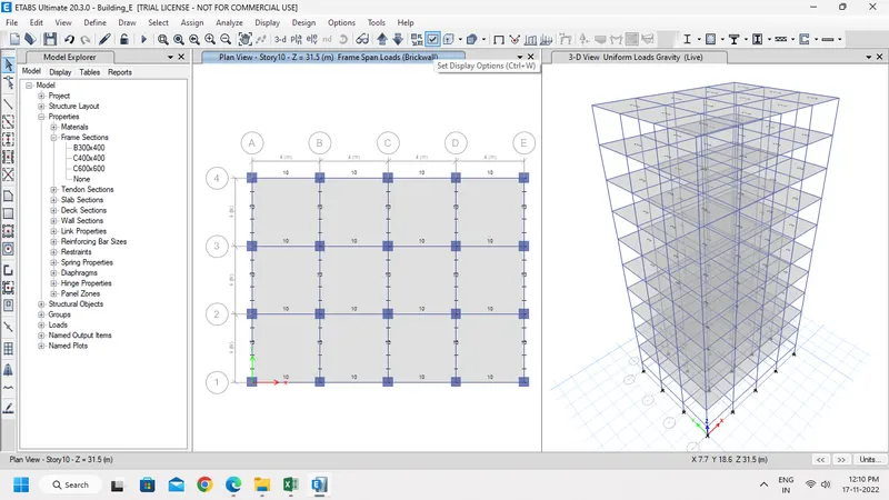
- Uncheck Beams & Slab and apply to all Windows. Then click OK.
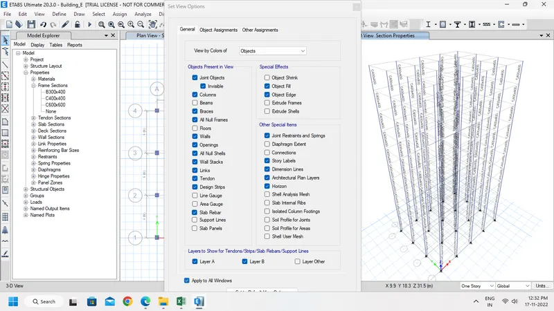
- Now the Beams and Slabs are disappeared.
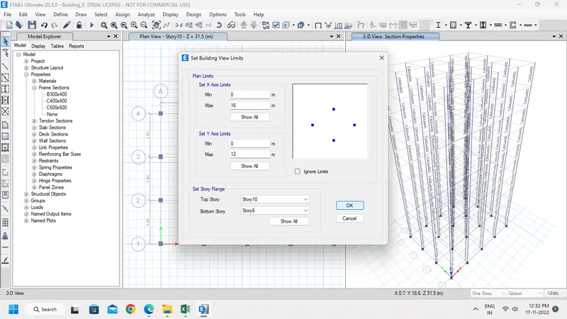
- In View Tab, Select Set Building View limits.
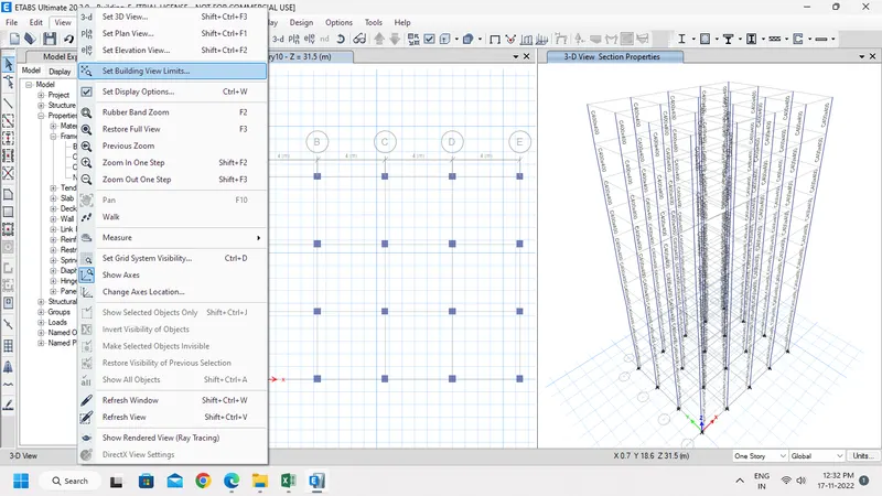
- A new pop-up window appears, in that Set Story Range Bottom Story as Story 6 and Top Story as Story 10.
- Then select all Columns.
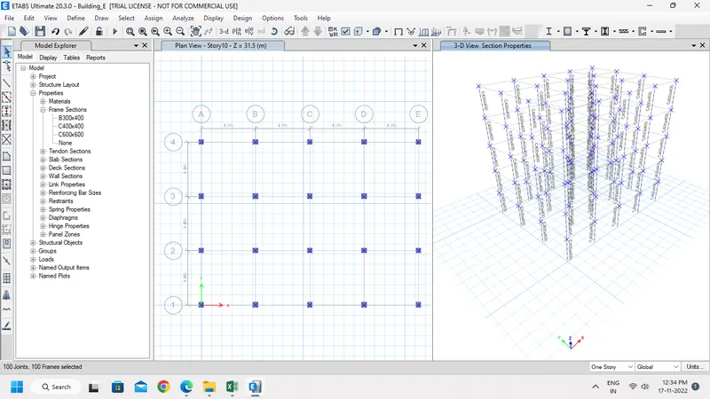
- In Model explorer, click Frame sections and select C400x400.
- Then Right Click to Assign C400x400 to the selected columns.
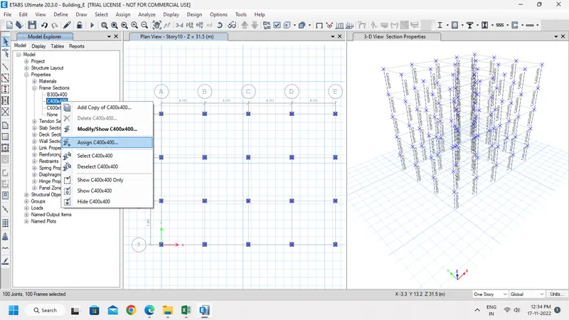
- In View Tab, Select Set Building View limits.
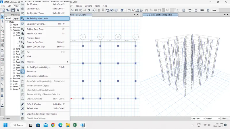
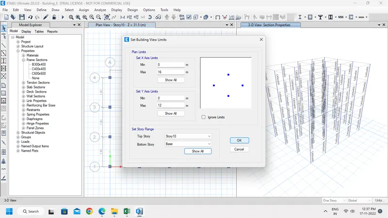
- A new pop-up window appears, in that Set Story as Show all.
- Go to Set Display Option.
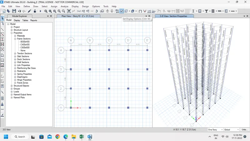
- Check Beams & Slab and apply to all Windows. Then click OK.
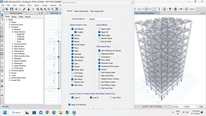
- Now the Beams and Slabs are re-appeared.
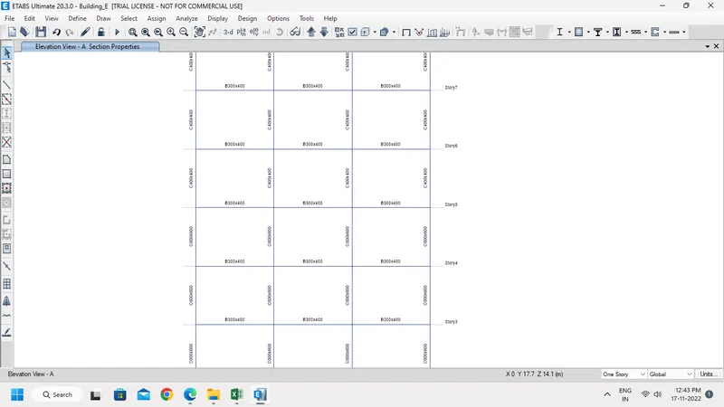
- To check the Section Properties assigned well, Close all other window and open a elevation window.
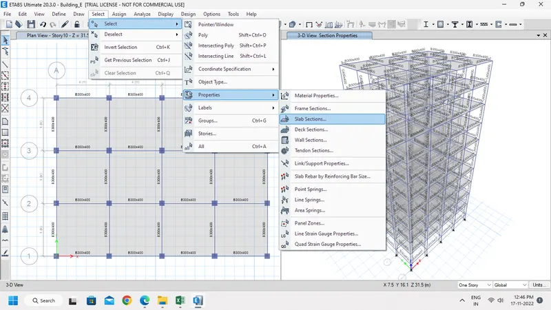
- Select all Slab from Select Tab.
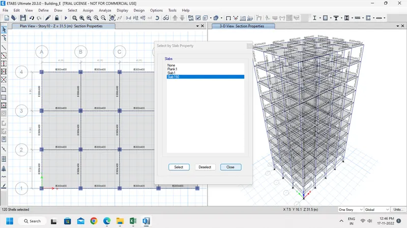
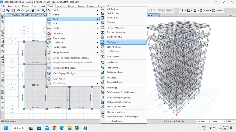
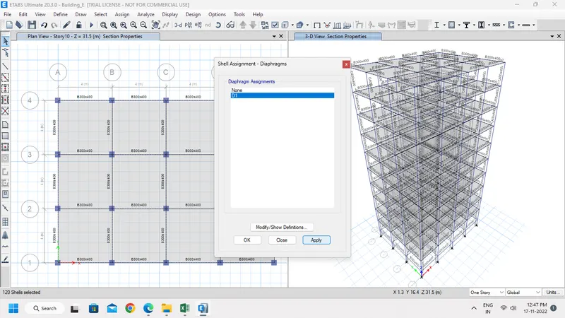
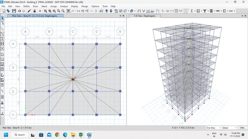
- Assign Diaphragm from Shell Option under Assign Tab.
Step 5:-
- Select Analyze Tab, then Check Model.
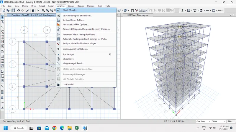
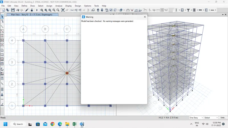
- Now click Run Analysis.
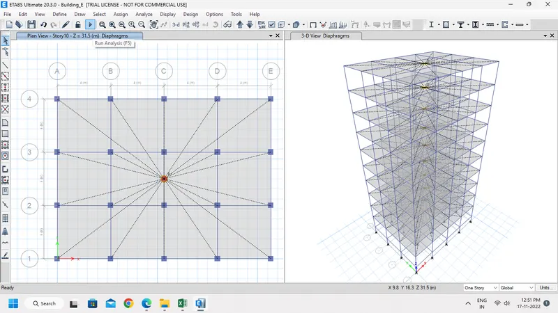
- Now we can see the model deformed.
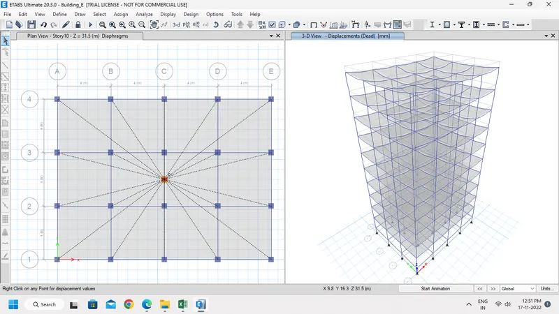
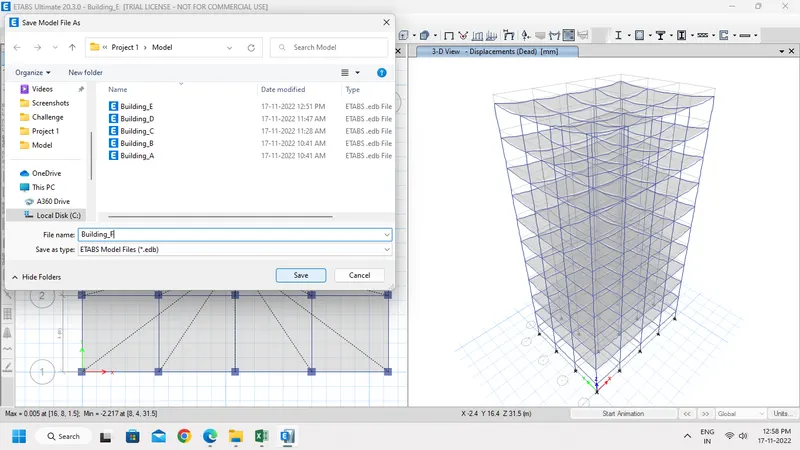
- Now save the file.
Building F:
Step 1:-
- In File Tab select Save as option to Save Building E as Building F.

Step 2:-
- Go to Select Tab, and choose Object Type. Then select all Columns.
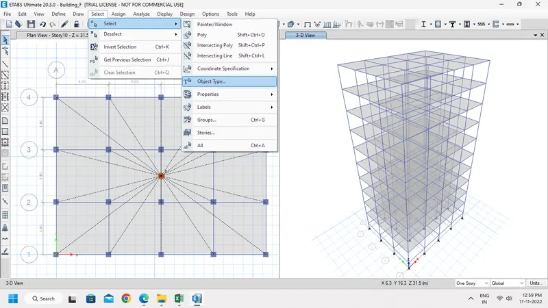
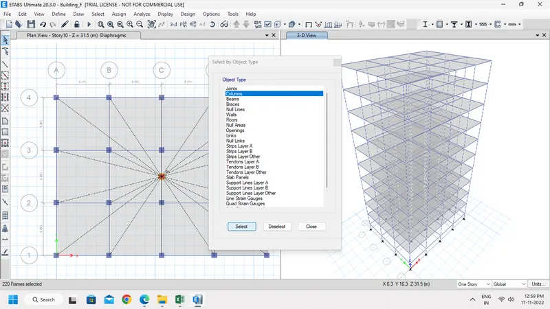
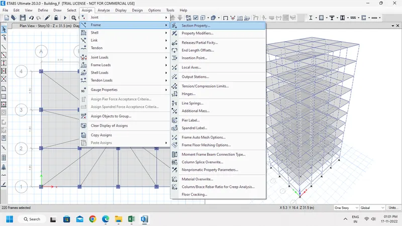
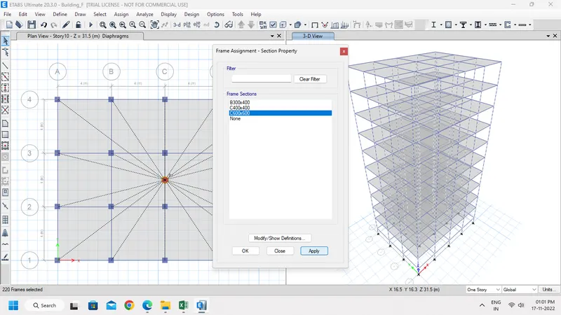
- In Assign Tab ->Frame -> Section Properties and select C600x600.
- Assign C600x600 to the selected columns.
- Select Slab from Select Tab.
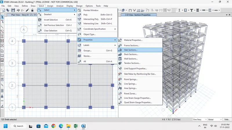
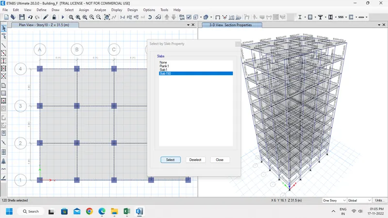
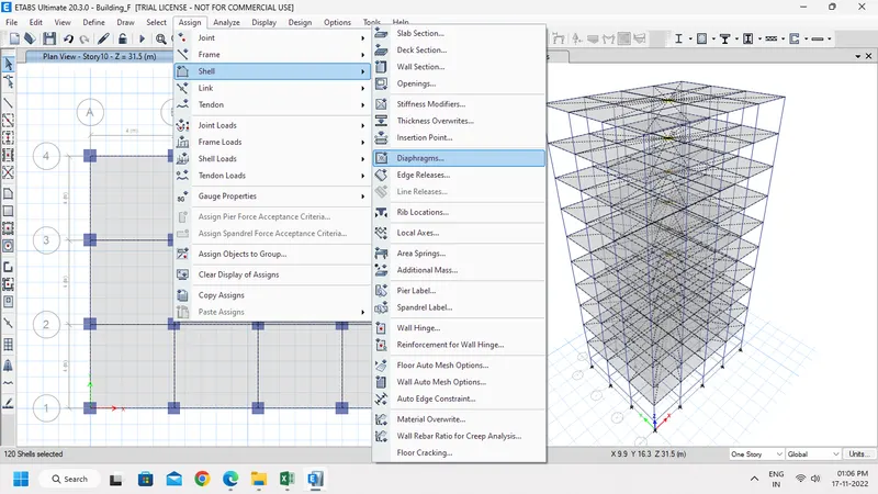
- Assign Diaphragm from Shell Option under Assign Tab.
Step 3:-
- Select Analyze Tab, then Check Model.
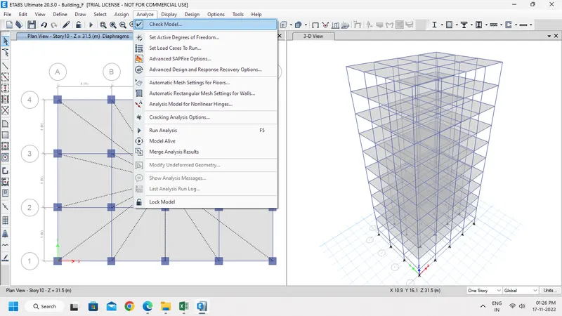
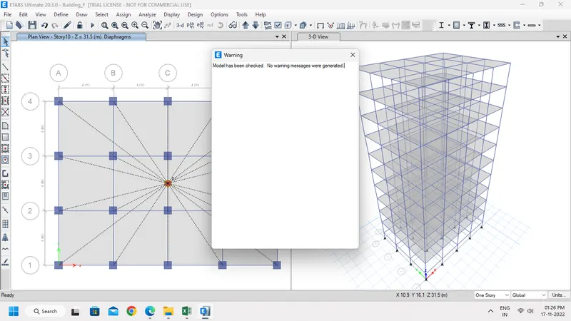
- Now click Run Analysis.
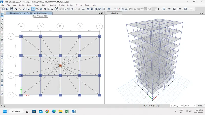
- Now we can see the model deformed.
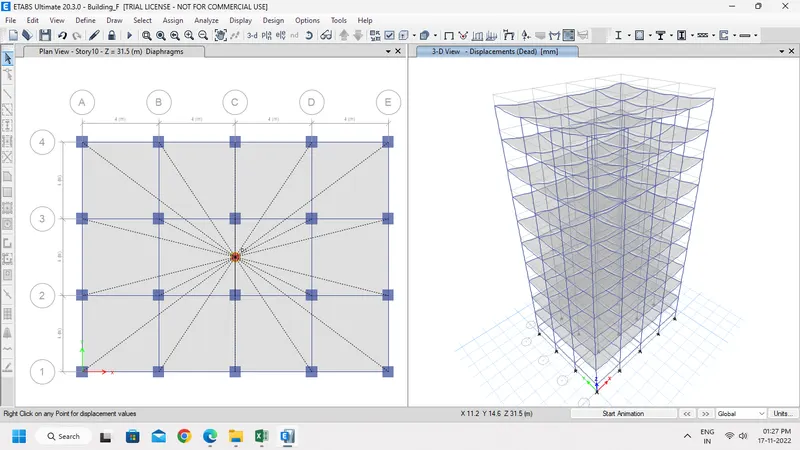
- Now save the file.
Building G:
Step 1:-
- In File Tab select Save as option to Save Building F as Building G.
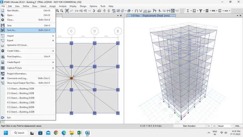
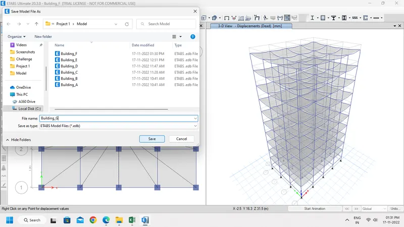
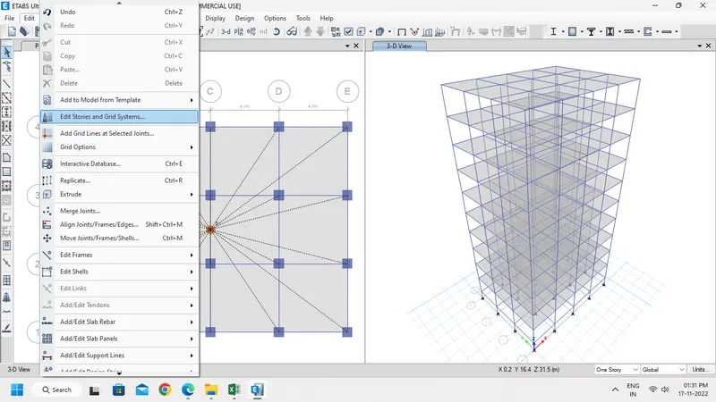
- In Edit Tab, selcet Edit Stories and Grid Systems.
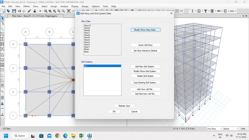
- A New pop-up window opens, in that Click Modify/Show Story Data.
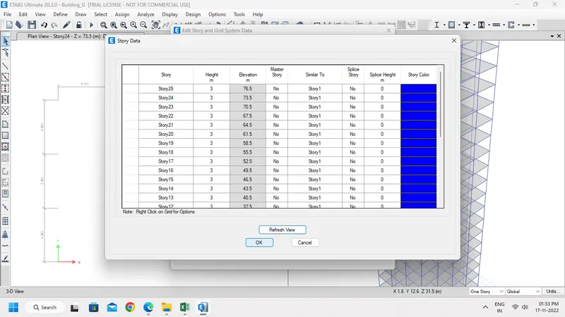
- Now add Fifteen more stories above Story 10 of height 3m each.
- And set Similar to Story 1.
Step 2:-
- Now check whether all loads applied to the model.
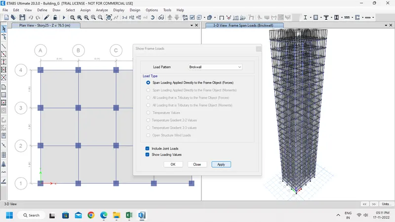
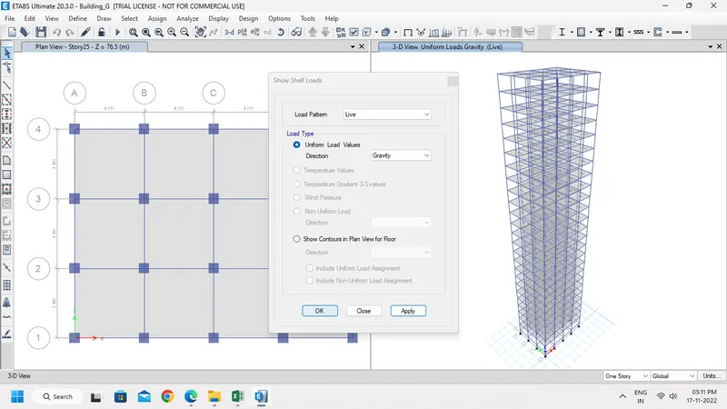
Step 3:-
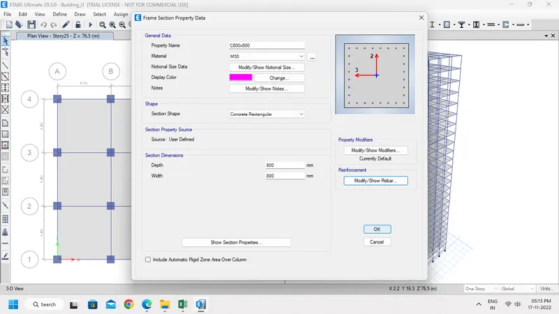
- In Define Tab, select Frame Sections.
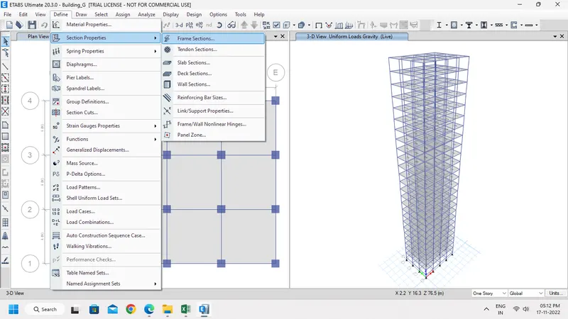
- A new pop-up window appears, add New property.
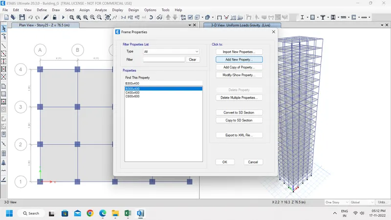
- And Rename it as C800x800 and change depth as 800mm and width as 800mm.
Step 4:-
- Go to Set Display Option.
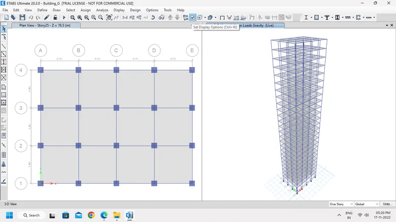
- Uncheck Beams & Slab and apply to all Windows. Then click OK.
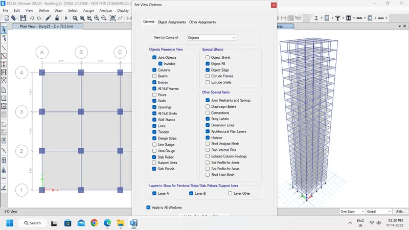
- Now the Beams and Slabs are disappeared.
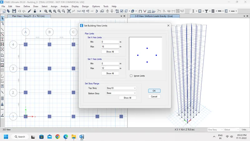
- In View Tab, Select Set Building View limits.
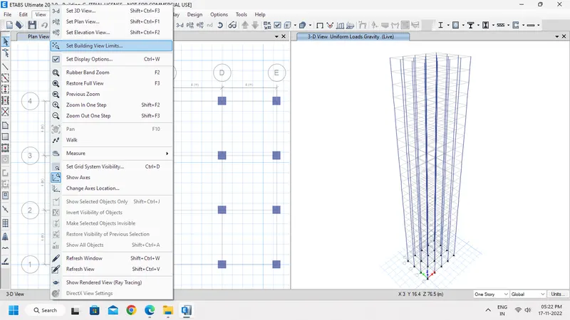
- A new pop-up window appears, in that Set Story Range Bottom Story as Base and Top Story as Story 10.
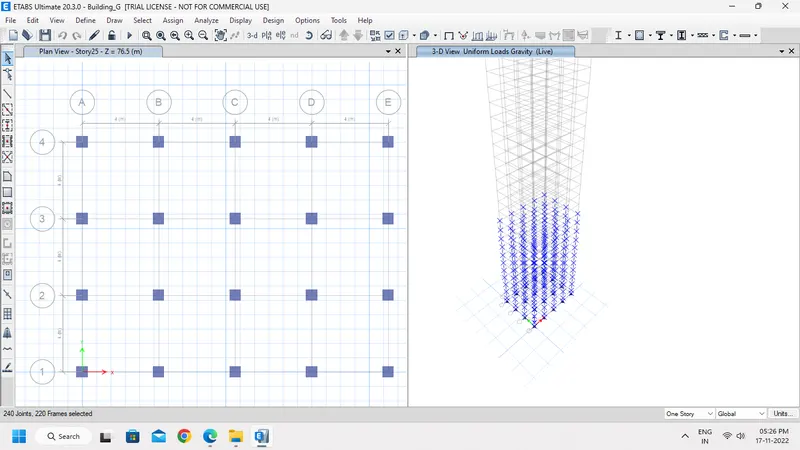
- Then select all Columns.
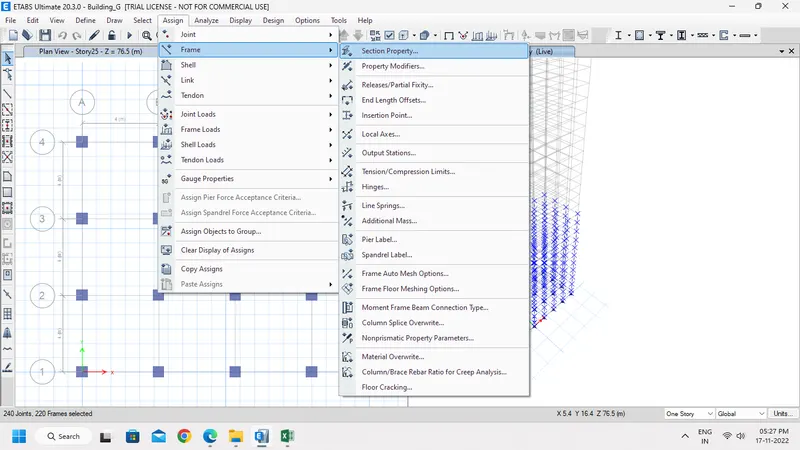
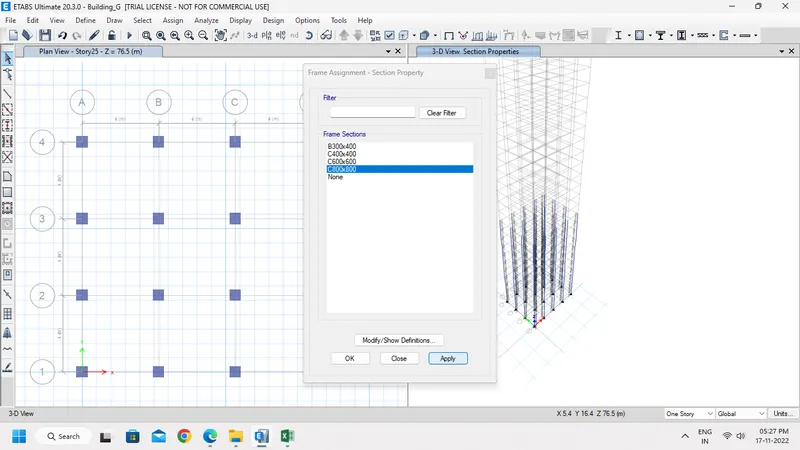
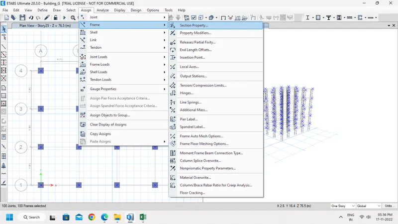
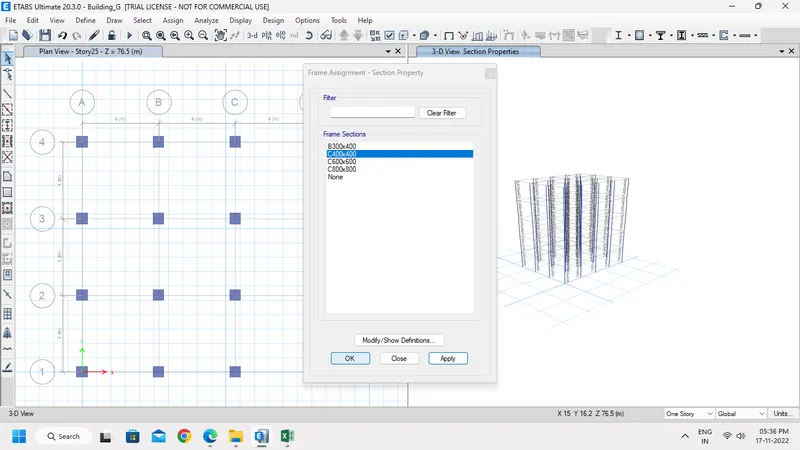
- In Assign Tab ->Frame -> Section Properties and select C800x800.
- Assign C800x800 to the selected columns.
- In View Tab, Select Set Building View limits.
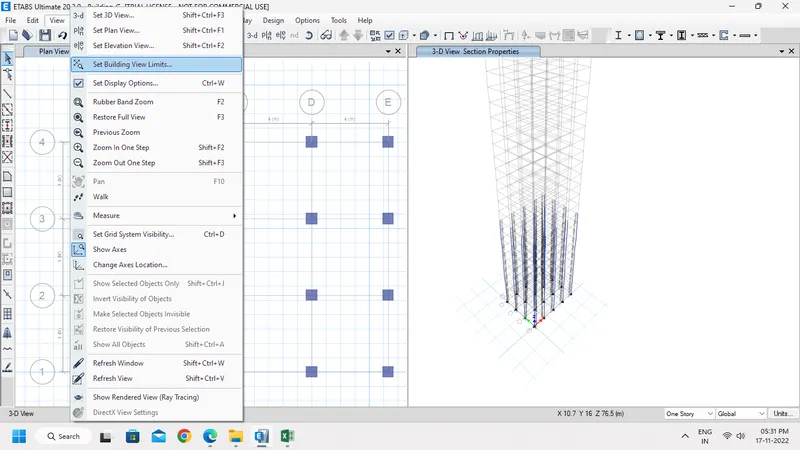
- A new pop-up window appears, in that Set Story Range Bottom Story as Story 11 and Top Story as Story 20.
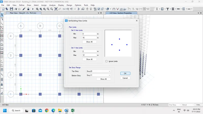
- Then select all Columns.
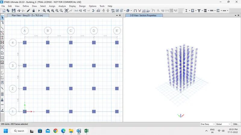
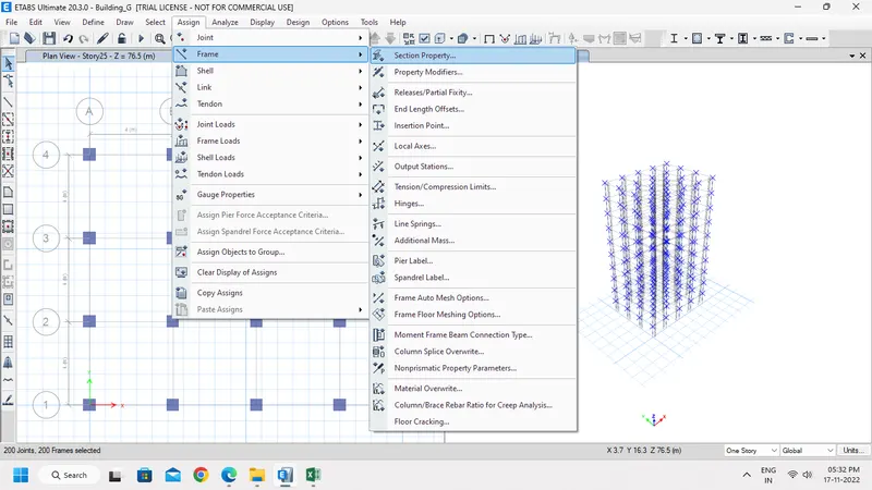
- In Assign Tab ->Frame -> Section Properties and select C600x600.
- Assign C600x600 to the selected columns.
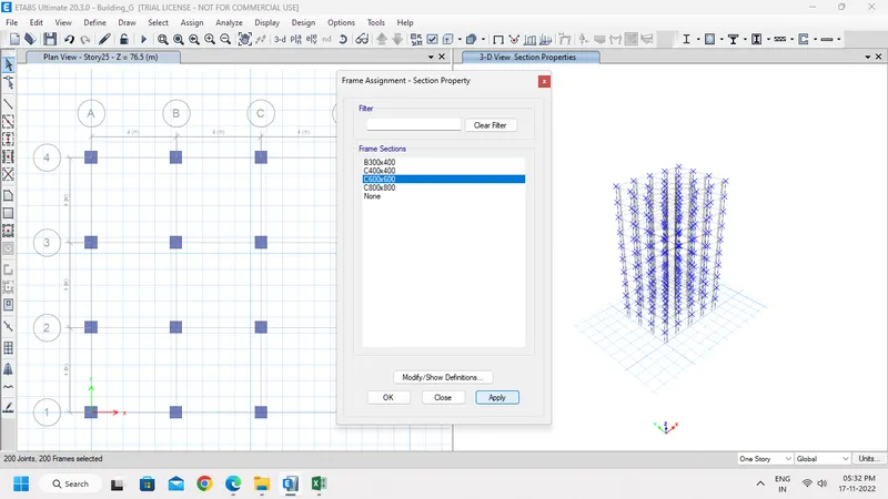
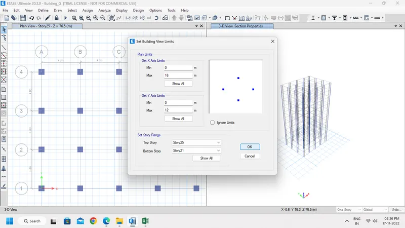
- In View Tab, Select Set Building View limits.
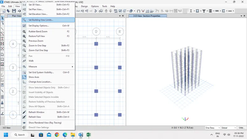
- A new pop-up window appears, in that Set Story Range Bottom Story as Story 21 and Top Story as Story 25.
- Then select all Columns.
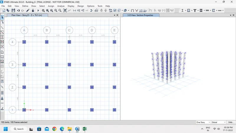
- In Assign Tab ->Frame -> Section Properties and select C400x400.
- Assign C400x400 to the selected columns.
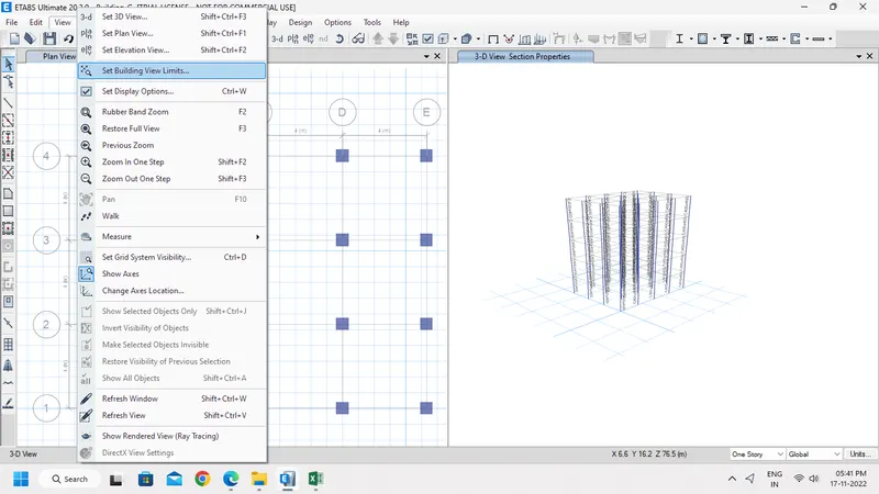
- In View Tab, Select Set Building View limits.
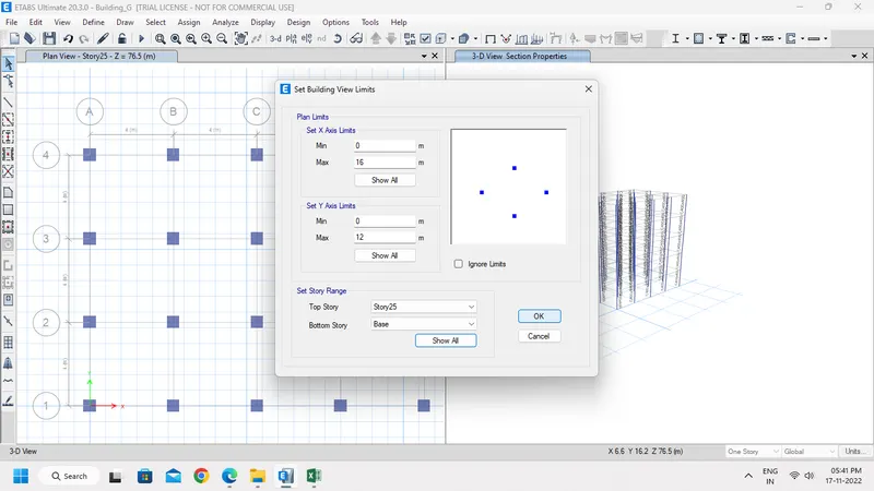
- A new pop-up window appears, in that Set Story as Show all.
- Go to Set Display Option.
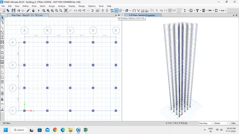
- Check Beams & Slab and apply to all Windows. Then click OK.
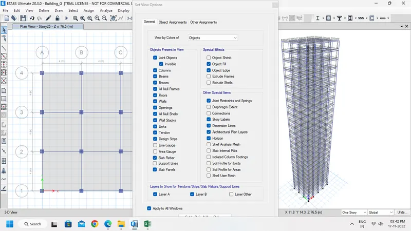
- Now the Beams and Slabs are re-appeared.
- To check the Section Properties assigned well, Close all other window and open a elevation window.
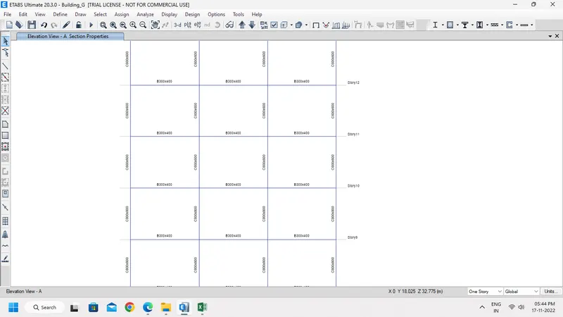
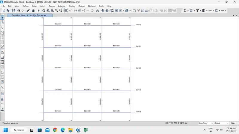
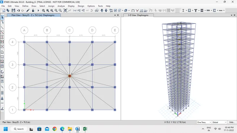
- Select all Slab from Select Tab.
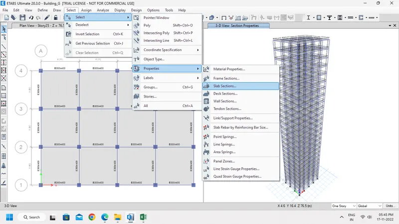
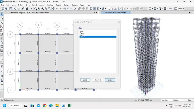
- Assign Diaphragm from Shell Option under Assign Tab.
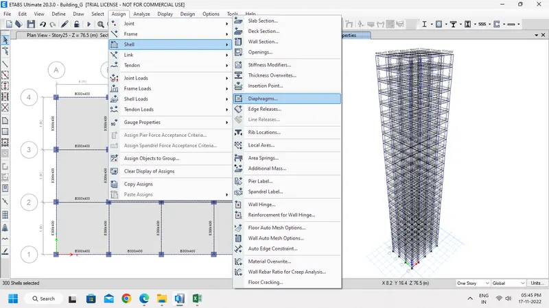
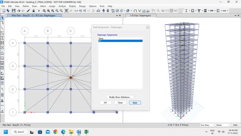
Step 5:-
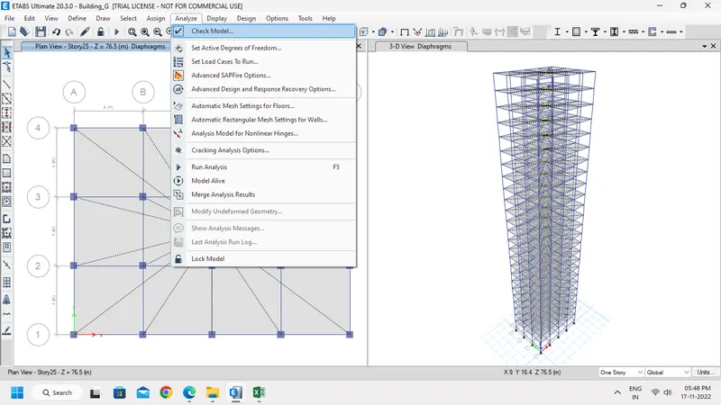
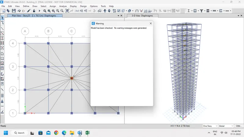
- Select Analyze Tab, then Check Model.
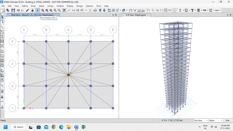
- Now click Run Analysis.
- Now we can see the model deformed.
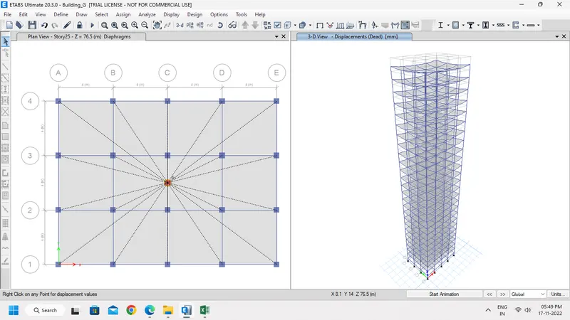
- Now save the file.
Building H:
Step 1:-
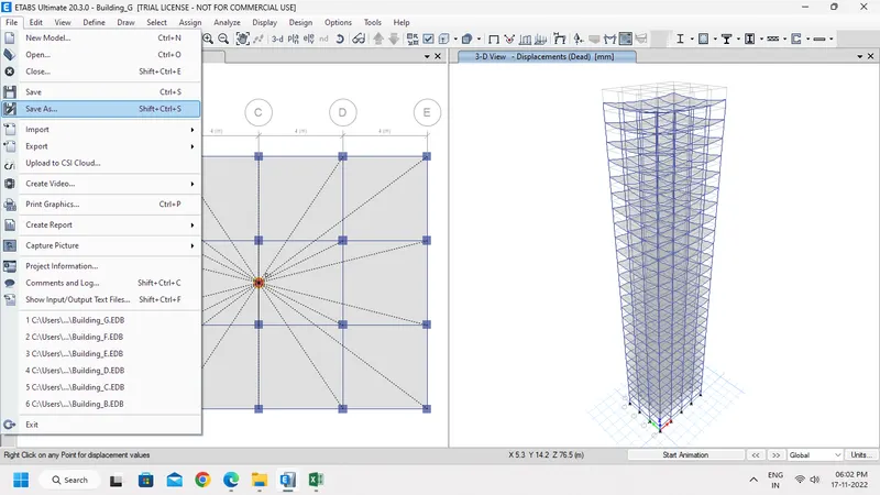
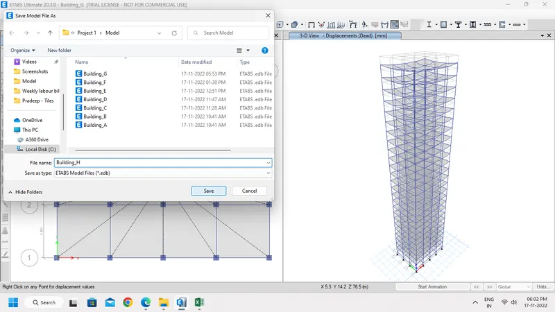
- In File Tab select Save as option to Save Building G as Building H.
Step 2:-
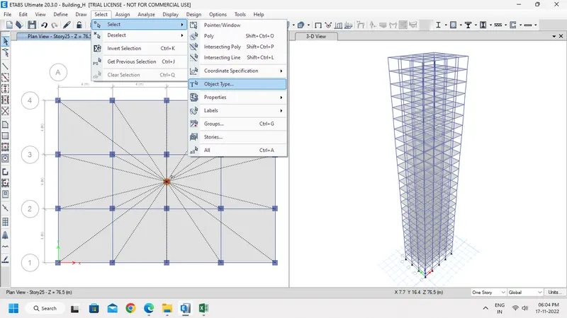
- Go to Select Tab, and choose Object Type. Then select all Columns.
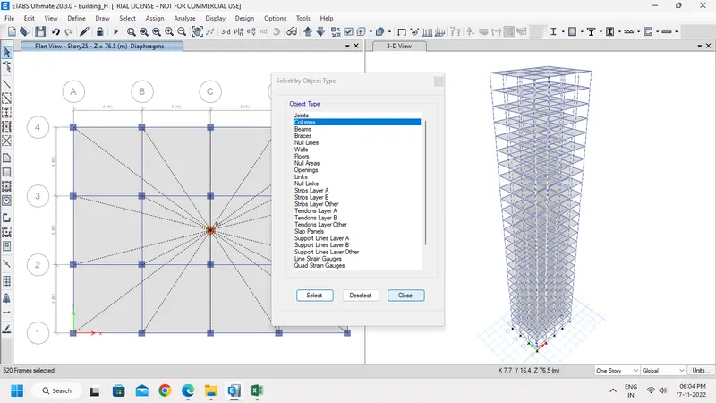
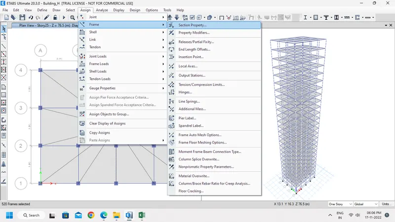
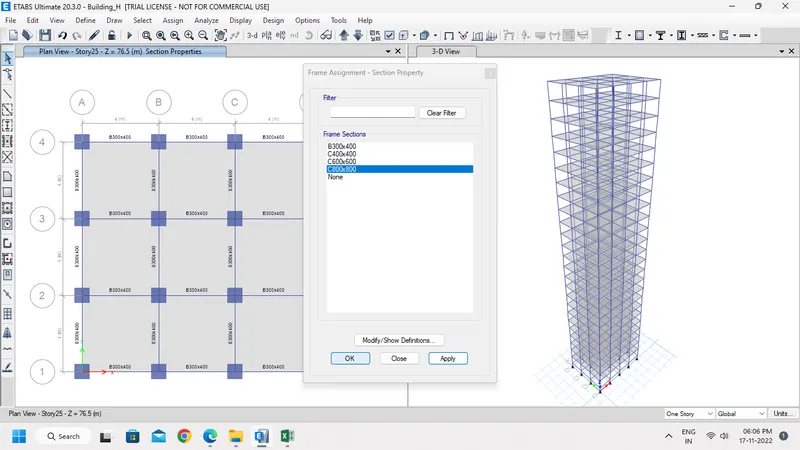
- In Assign Tab ->Frame -> Section Properties and select C800x800.
- Assign C800x800 to the selected columns.
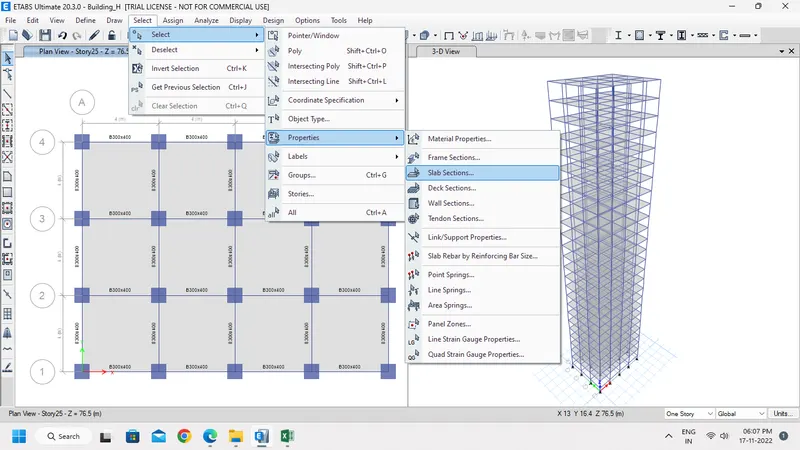
- Select Slab from Select Tab.
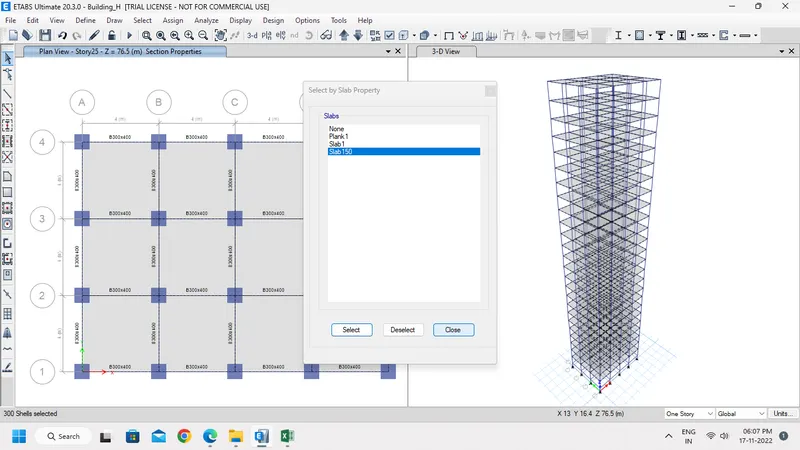
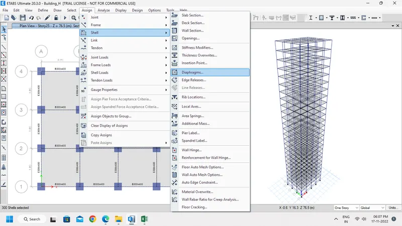
- Assign Diaphragm from Shell Option under Assign Tab.
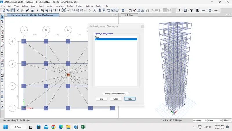
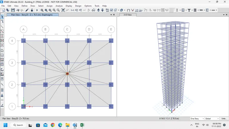
Step 3:-
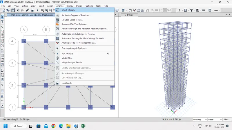
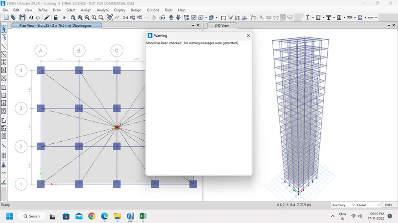
- Select Analyze Tab, then Check Model.
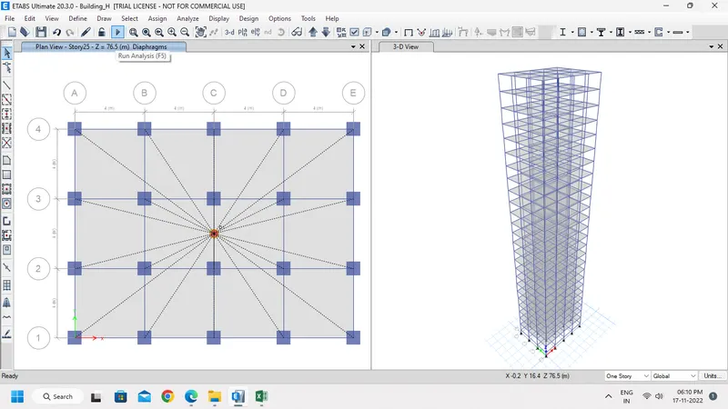
- Now click Run Analysis.
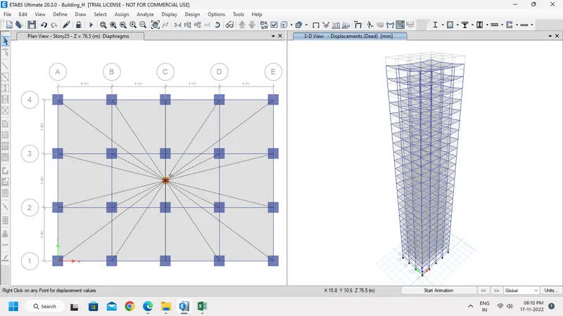
- Now we can see the model deformed.
- Now save the file.
Building J:
Step 1:-
- In File Tab select Save as option to Save Building H as Building J.
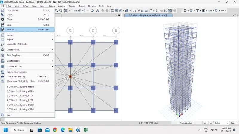

Step 2:-
- Select Slab from Select Tab.
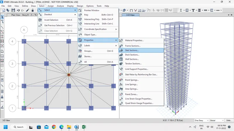
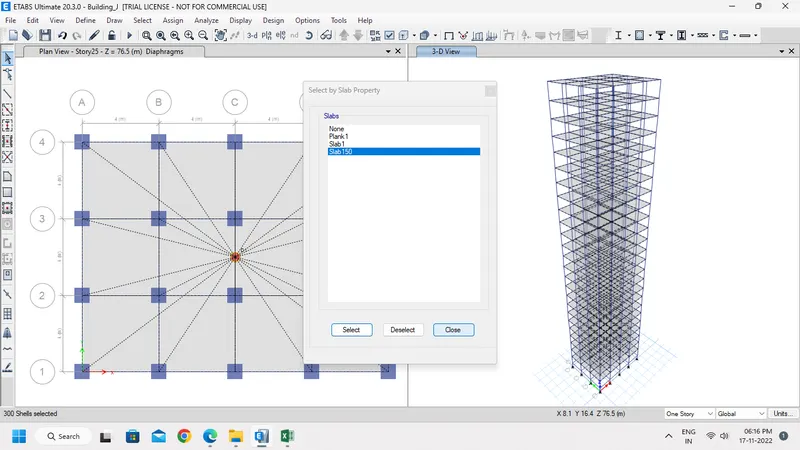
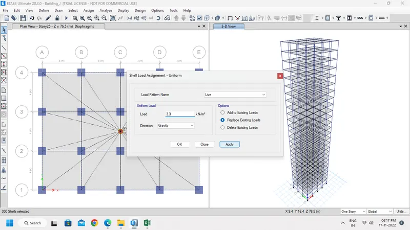
- In Assign Tab, Select Shell Load and then click Uniform.
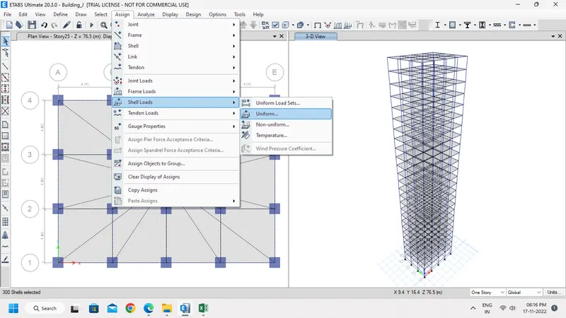
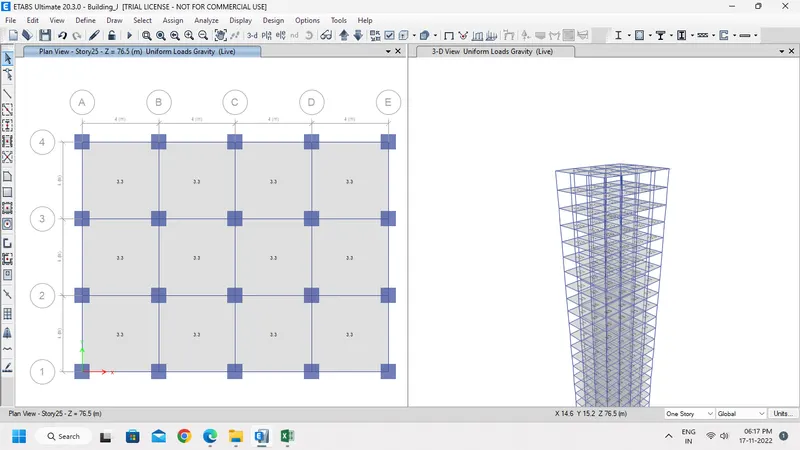
- A New Pop-up window opens, in that select Live Load of 3.3kN/m2. (ie. Addition of 10% Imposed then Building H).
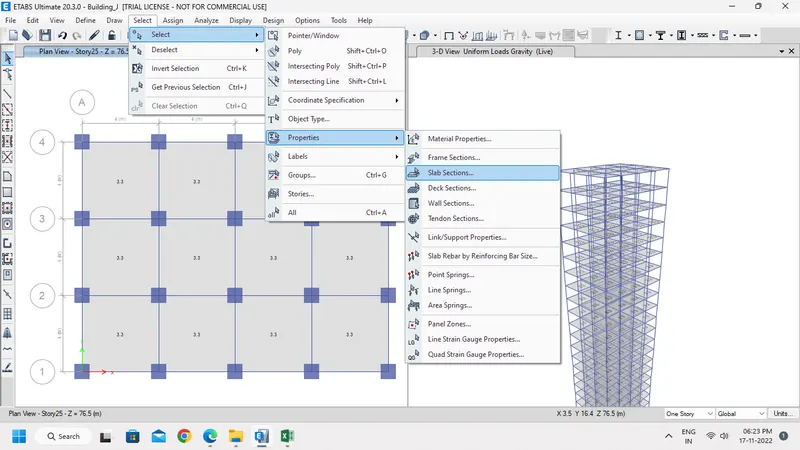
- Select Slab from Select Tab.
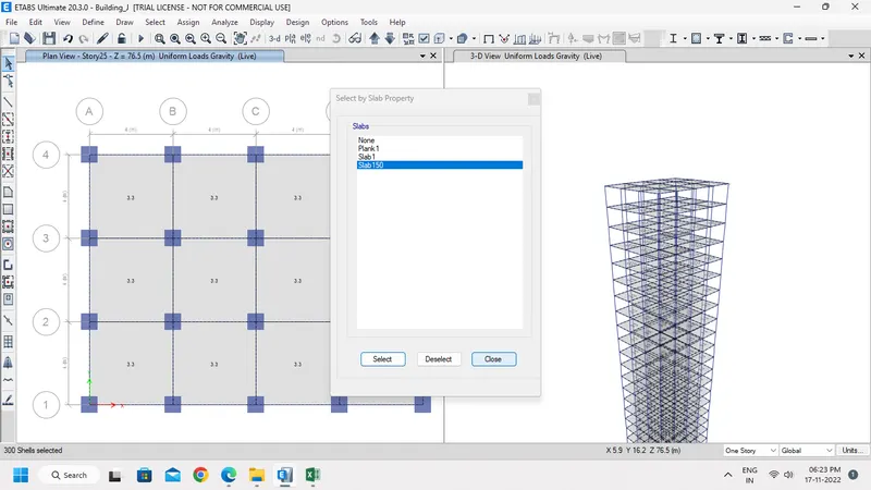
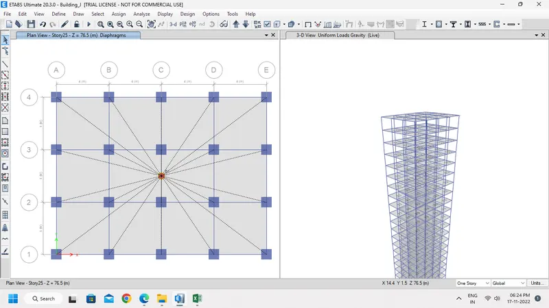
- Assign Diaphragm from Shell Option under Assign Tab.
Step 3:-
- Now click Run Analysis.
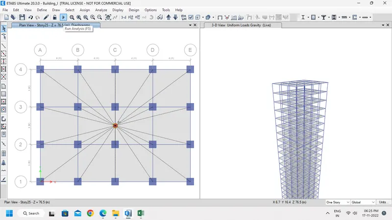
- Now we can see the model deformed.
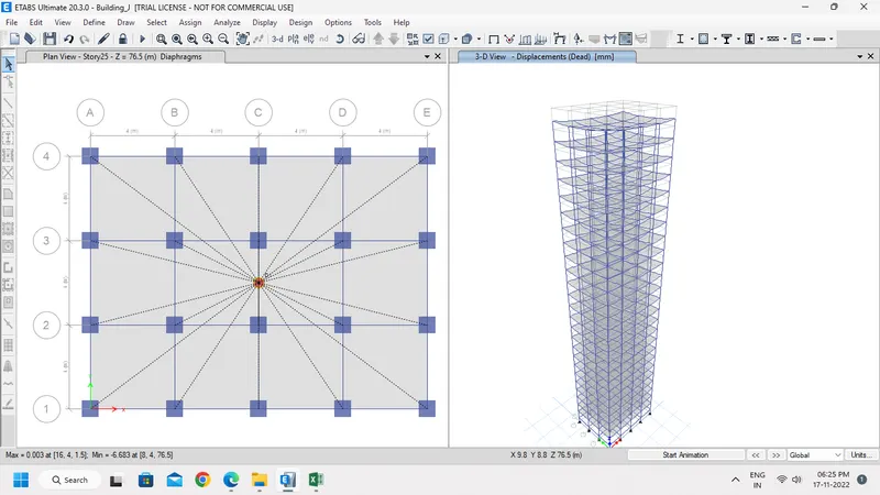
- Now save the file.
Building K:
Step 1:-
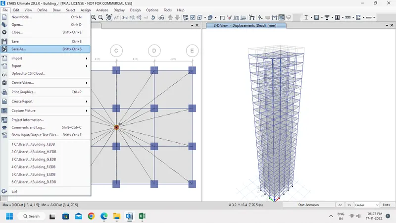
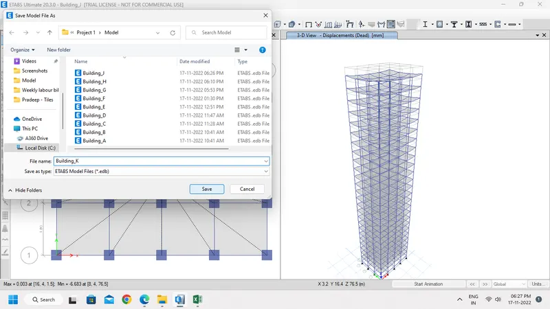
- In File Tab select Save as option to Save Building H as Building J.
Step 2:-
- Select Slab from Select Tab.
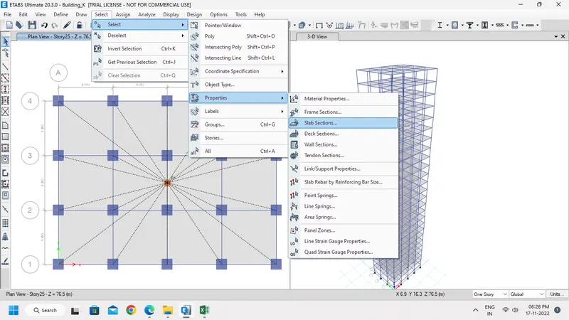
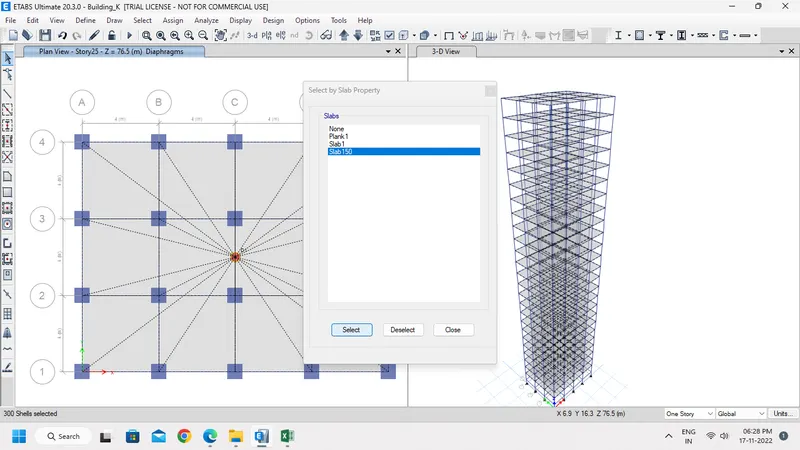
- In Assign Tab, Select Shell Load and then click Uniform.
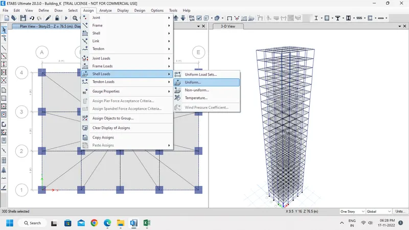
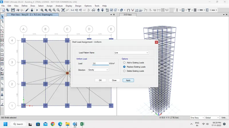
- A New Pop-up window opens, in that select Live Load of 3.6kN/m2. (ie. Addition of 20% Imposed than Building H).
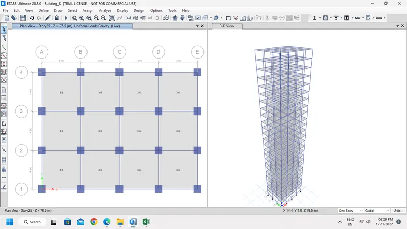
- Select Slab from Select Tab.
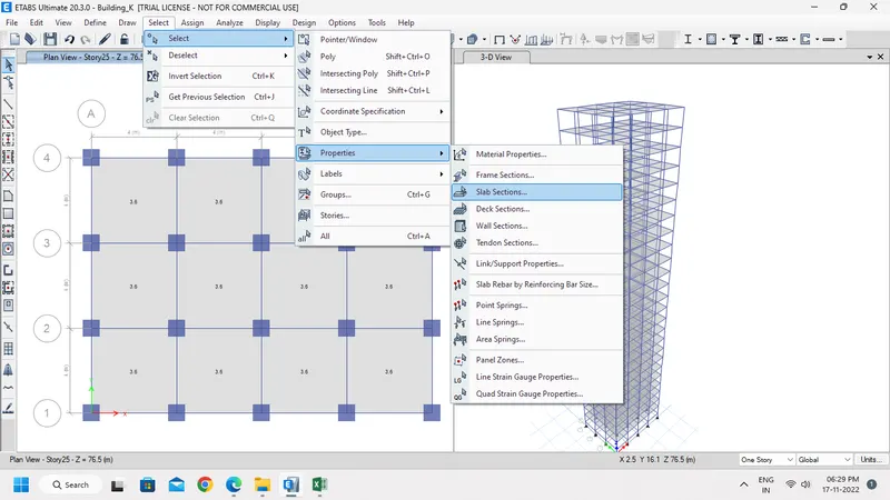

- Assign Diaphragm from Shell Option under Assign Tab.
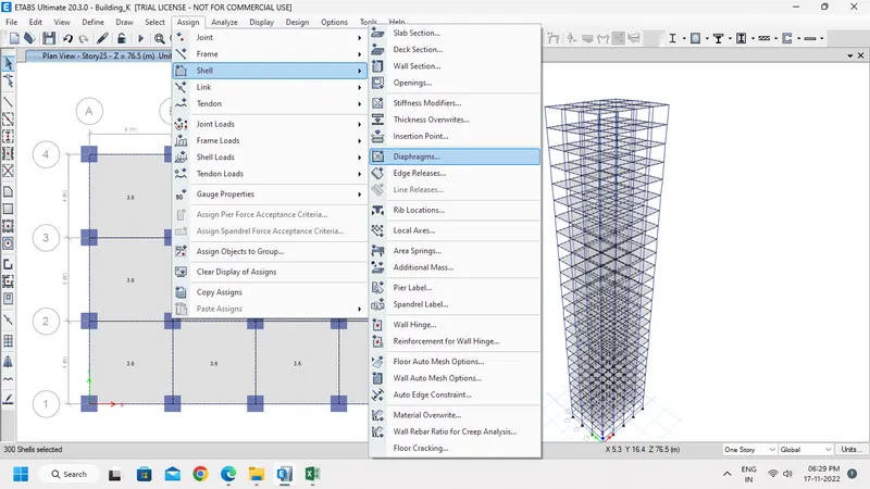
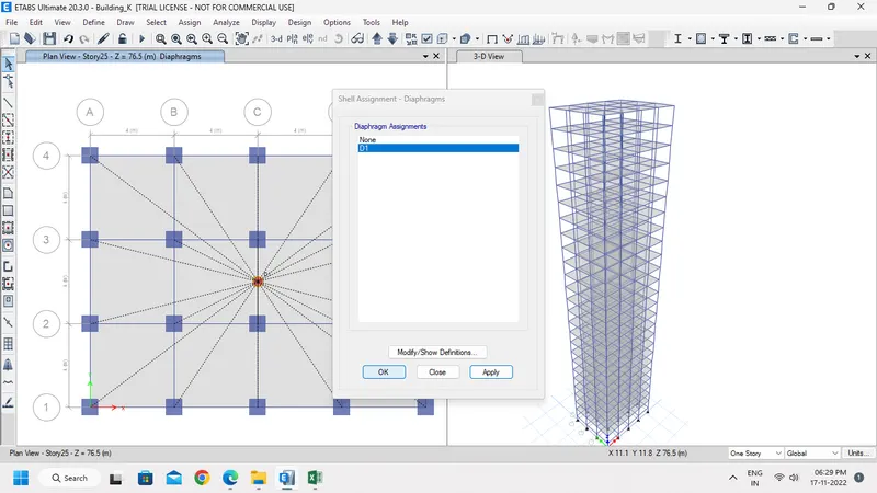
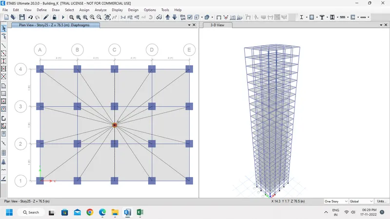
Step 3:-
- Now click Run Analysis.
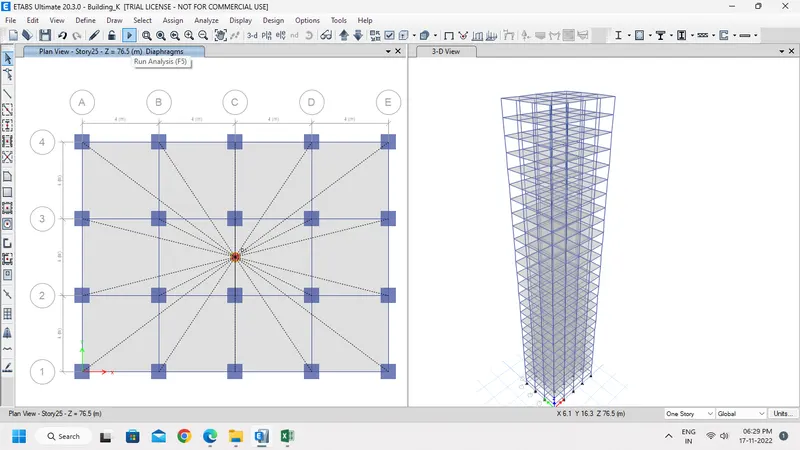
- Now we can see the model deformed.
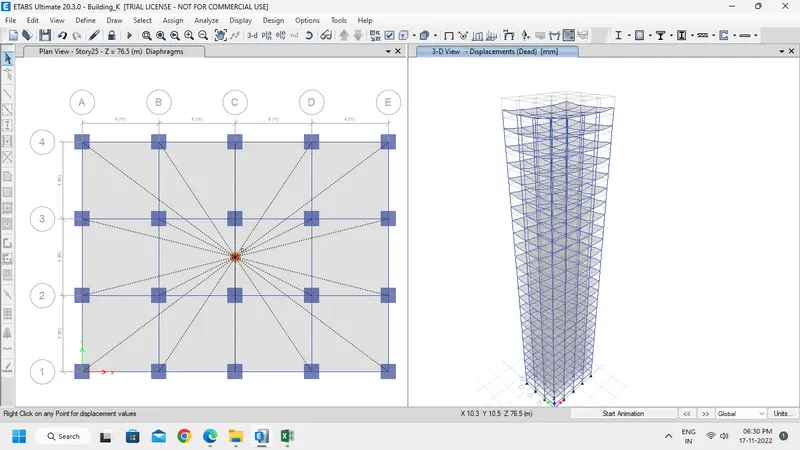
- Now save the file.
Result:-
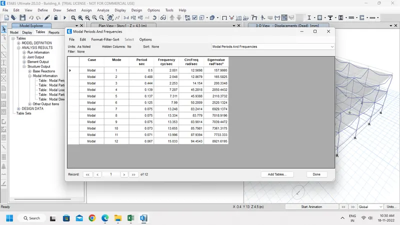
Building A:
The following tables shows Modal Periods and Frequencies:
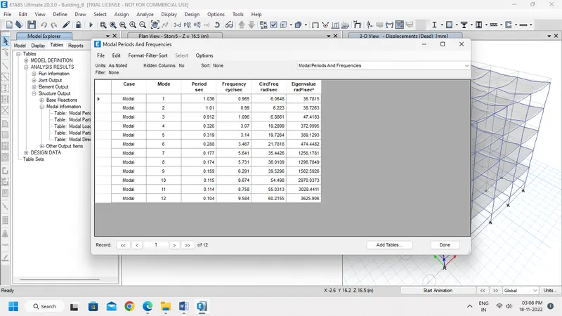
Building B:
The following tables shows Modal Periods and Frequencies:
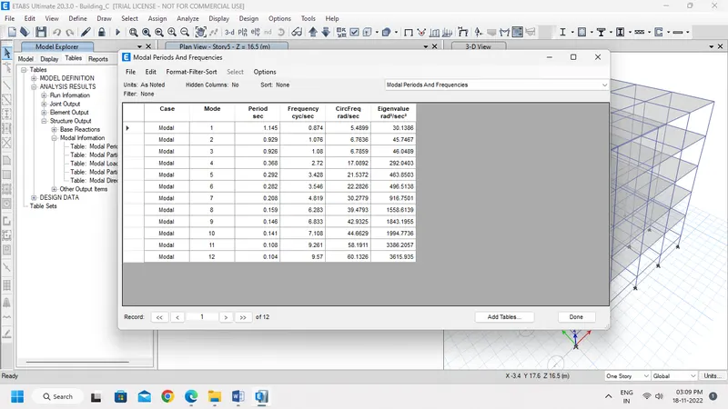
Building C:
The following tables shows Modal Periods and Frequencies:
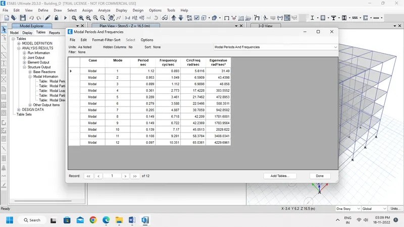
Building D:
The following tables shows Modal Periods and Frequencies:
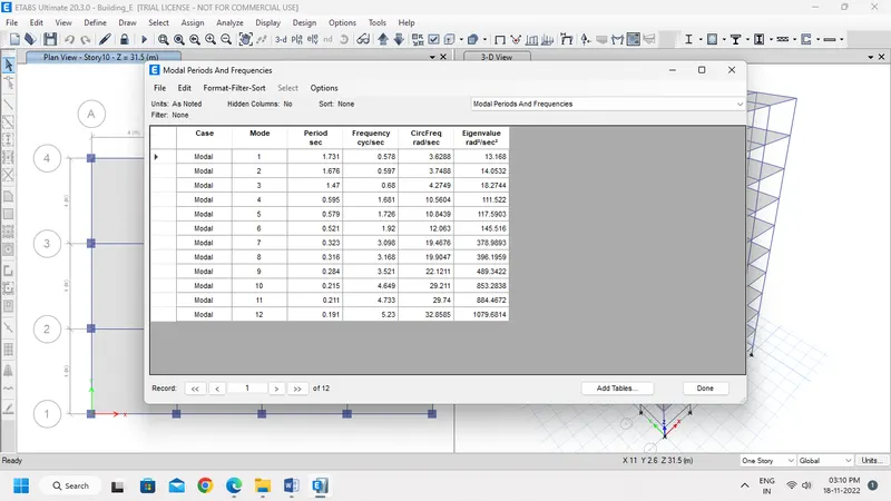
Building E:
The following tables shows Modal Periods and Frequencies:
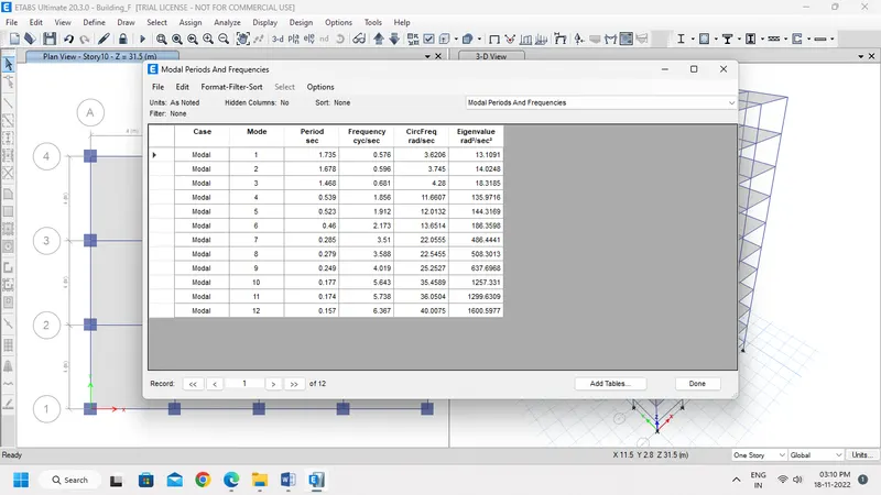
Building F:
The following tables shows Modal Periods and Frequencies:
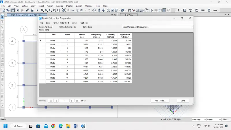
Building G:
The following tables shows Modal Periods and Frequencies:
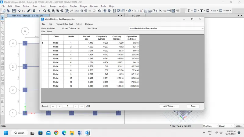
Building H:
The following tables shows Modal Periods and Frequencies:
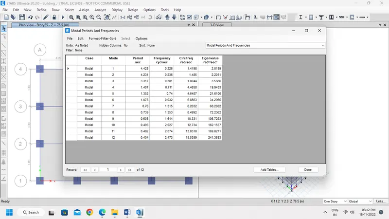
Building J:
The following tables shows Modal Periods and Frequencies:
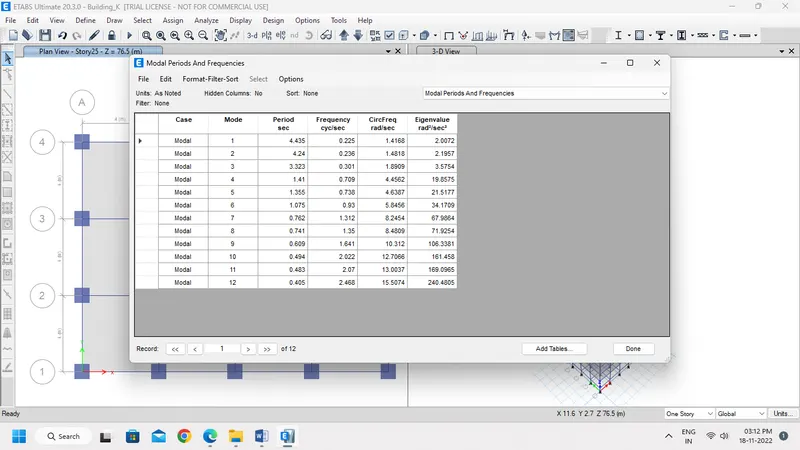
Building K:
The following tables shows Modal Periods and Frequencies:
Building B (Zero):
- Building B (Zero) indicates the flexural stiffness of beams to that of adjoining columns is very small.
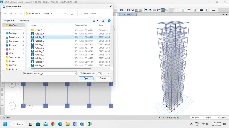
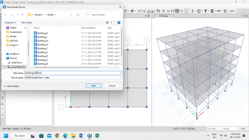
- Open Building B and Save as Building_B (Zero) in File Tab.
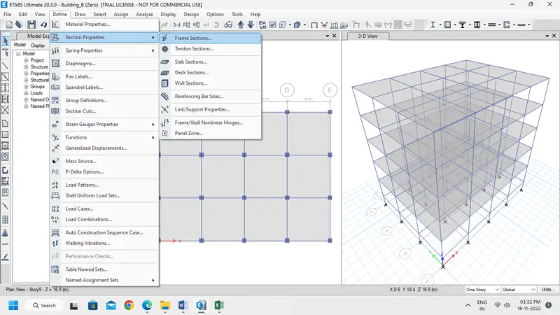
- In Define Tab, select Section Properties and click Frame sections.
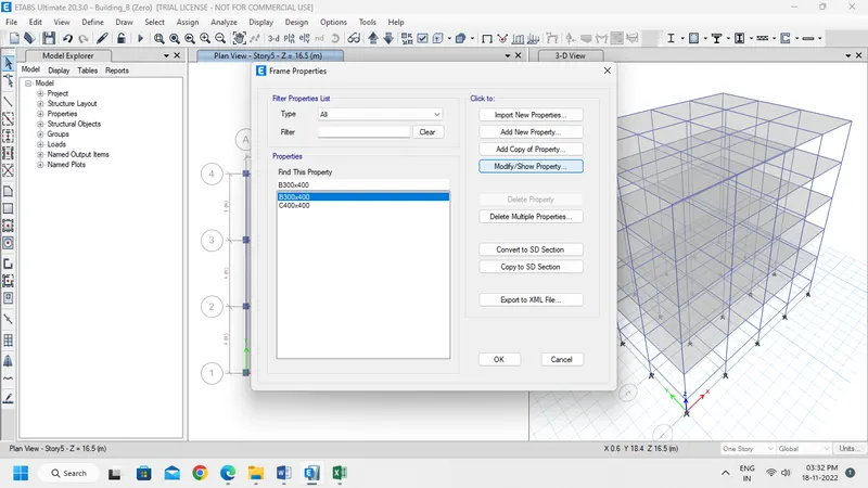
- A pop-up window opens, then select the Beam B300x400.
- Then click Modify/Show property. And click Modify/Show Modifier.
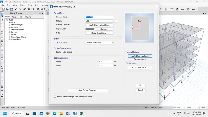
- Again a window opens, in that change Moment of Inertia to 0.1.
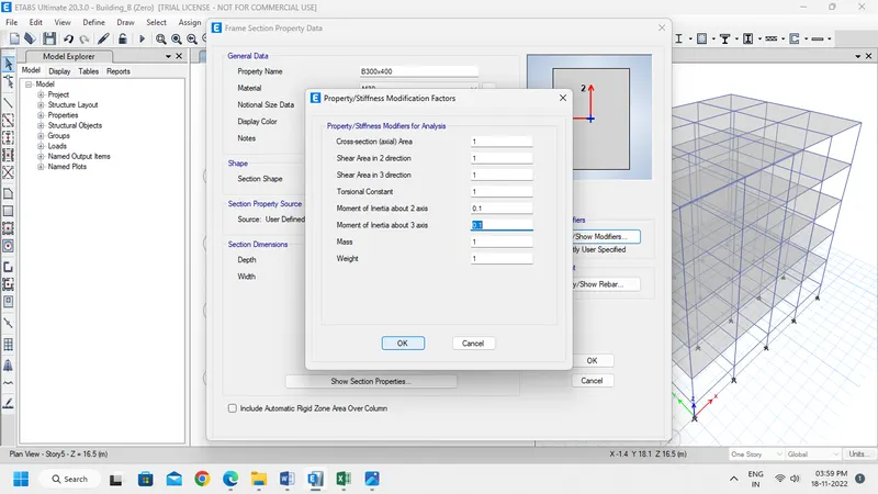
- Now Run Analysis.
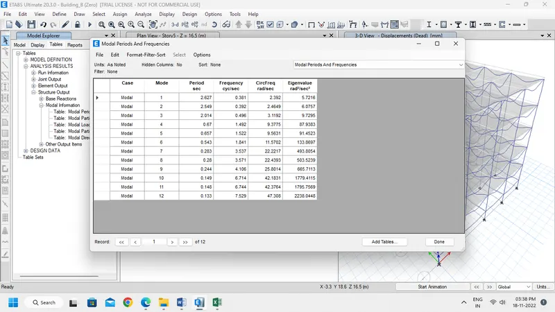
- Then check the time period.
Building H (Zero):
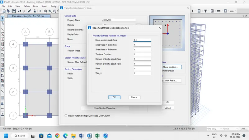
- Building H (Zero) indicates the Axial cross-sectional area of columns is very small.
- Open Building H and Save as Building_H (Zero) in File Tab.
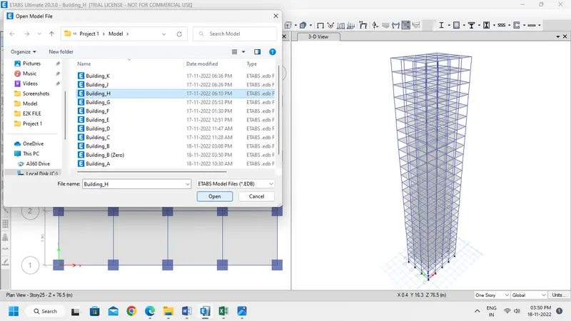
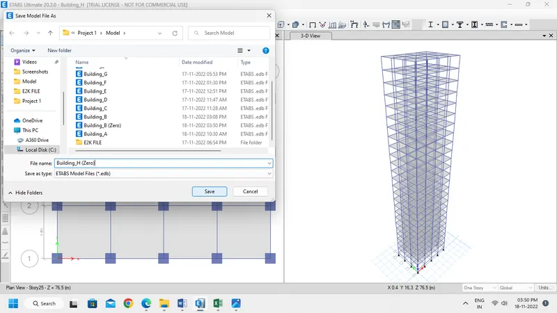
- In Define Tab, select Section Properties and click Frame sections.
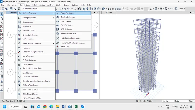
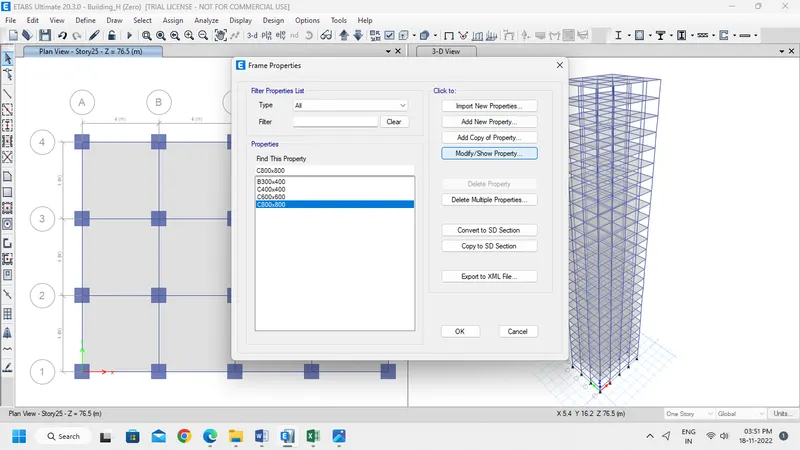
- A pop-up window opens, then select the Column C800x800.
- Then click Modify/Show property. And click Modify/Show Modifier.
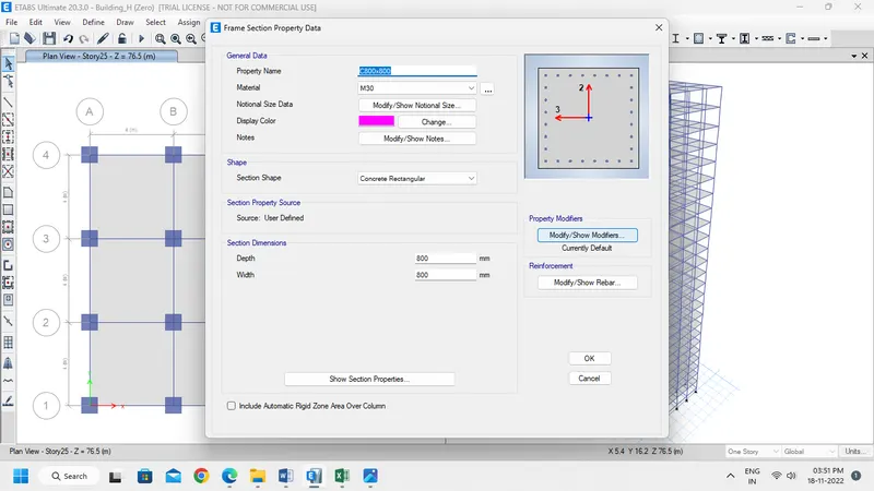
- Again a window opens, in that change Aixal Cross-sectional area to 0.1.
- Now Run Analysis.
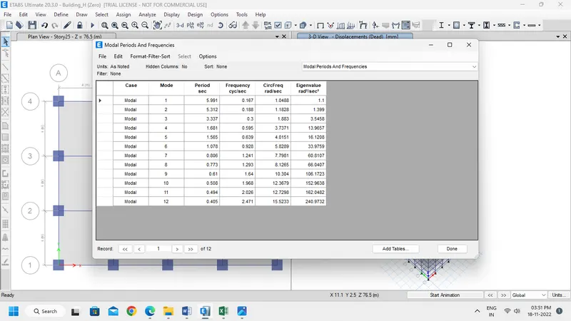
- Then check the time period.
Building B (Fixed):
- Building B (Fixed) indicates the Base columns is Fixed.
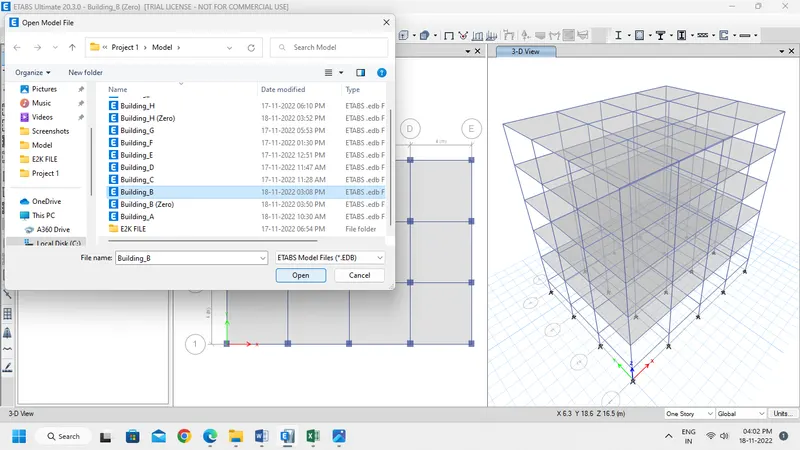
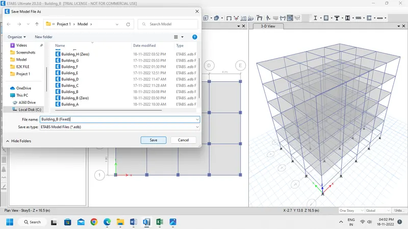
- Open Building B and Save as Building_B (Fixed) in File Tab.
- Select all base of the columns.
- In Assign Tab, select Joints and click Restraints.
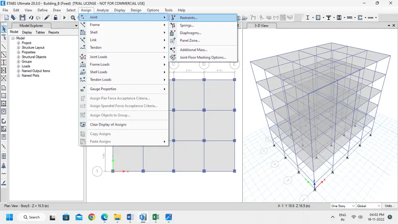
- A pop-up window opens, then select the Fixed support.
- Then click Apply.
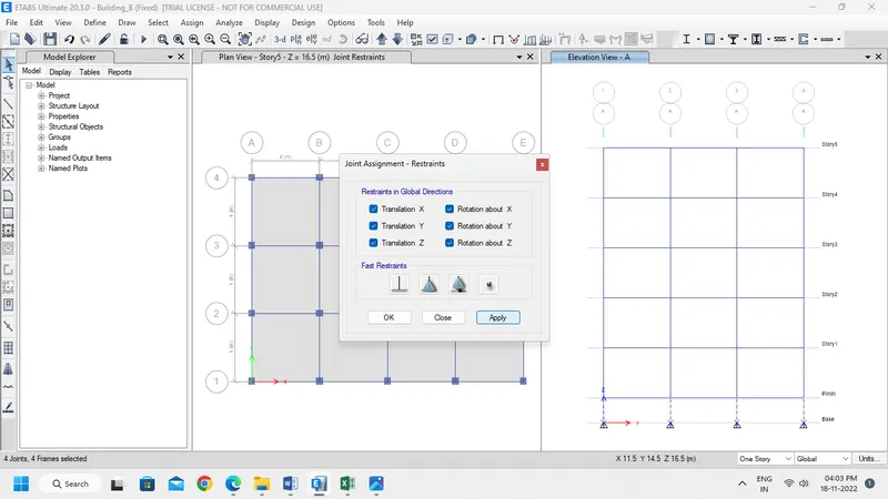
- Now Run Analysis.
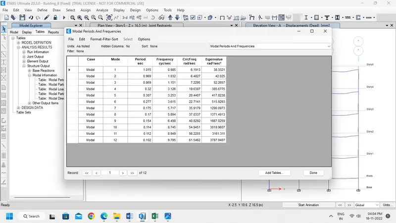
- Then check the time period.
Conclusion:-
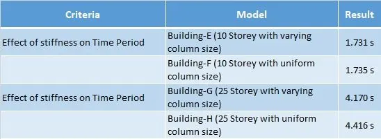
- In both E & F and G & H, the difference in time period is very less.
- In building E & F, the total mass of the structure varies as the column size varies in Building E whereas in building F the column size is uniform. Similarly, in building G & H also both the buildings are 25 storey buildings but their masses varies due to the variation in column sizes.
- Now, considering the stiffness of the structures, in both the structures the columns are arranged in a regular manner and hence the there is no much shift in the centre of stiffness from centre of mass. Hence, the small difference in time period of the two buildings are mainly due to the difference in their masses.
`T=(2π)⋅√m/k. Hence, T∝m and T∝1/k`
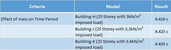
- All the three buildings have same storey height and column sizes, but the mass imposed on it varies.
- Here, the variation of time period in the three buildings is very minimal and this variation is due to the variation in the mass imposed on it which adds to the total mass of the building.
- Since the time period is directly proportional to mass, the variation in time period is given as K>J>H.
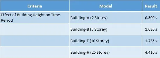
- From the above table it is clear that, with the increase in height the time period of the building increases.
- This is because as the height increases the stiffness of the building decreases, as stiffness is inversely proportional to height of the structure and as the stiffness decreases the time periods of the building increases as `T∝1/k`.
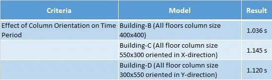
- In Building C the longer edge of the column is arranged in X direction as shown in the figure below. Hence, the stiffness will be more in X direction compared to y direction. So, the time period will be lesser in X direction and it will be more in Y direction. That is the reason that for this building the time period in X direction is the least.
- In Building D, the longer edge of the column is arranged in Y direction as shown below and as such the stiffness of the structure in the Y direction is higher compared to X direction. So, the time period of the structure will be lesser in the Y direction than in X direction.
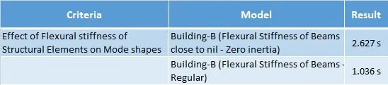
-
From table, it is clear that the time period of the building has been increased. As the flexural stiffness of the beam is reduced, the building becomes more flexible and the time period is increased hence maintaining the inverse proportionality between time period and stiffness.
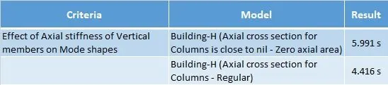
- Here also, as the axial stiffness of column is reduced, the time period of the building is increased.
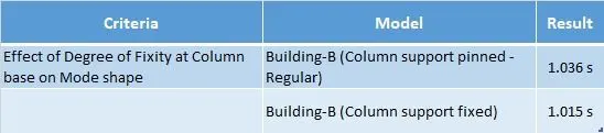
- From the table we can understand that, as the support is changed to fixed support the time period of the building is reduced.