Project 1_Comparative study of different storey buildings for Seismic forces
Aim: To study the comparative study of different storey buildings for Seismic forces
Procedure:
A)For 2 sotrey building
- Open Etab software click on new model
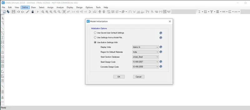
- Model intialization dialogue box appears enter the details in it, click on ok
-
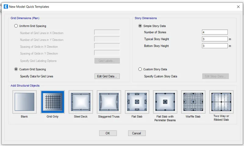
- From new model quick template select custom grid spacing and click in edit grid data
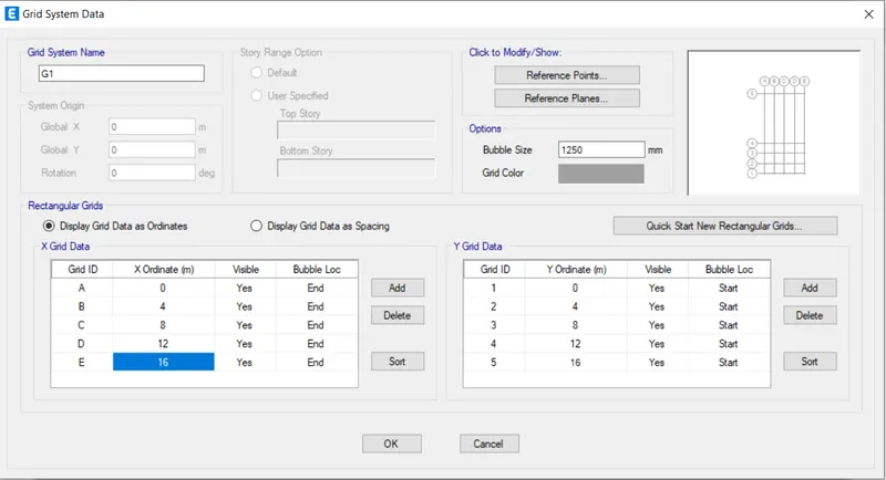
- Add number of grids as mentioned in the question and enter the details in it and click on ok.
- Then click on custom storeydata and select edit storeydata
- Now in storeydata edit the storeyand height and all other necessary details
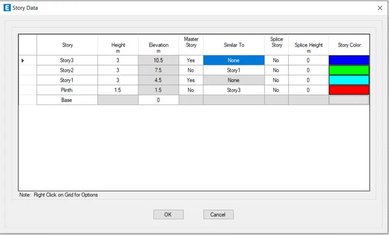
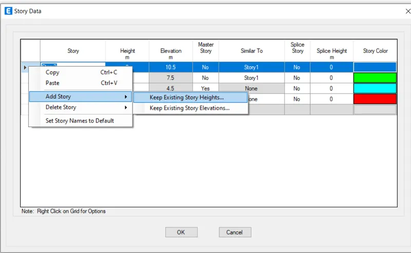
- Then select on add storeyand and click on keep existing storeyheight and add no of storeymentioned and click on ok
- Now 2 storey has been created above the plinth level
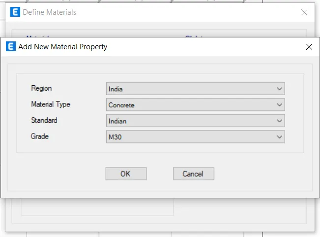
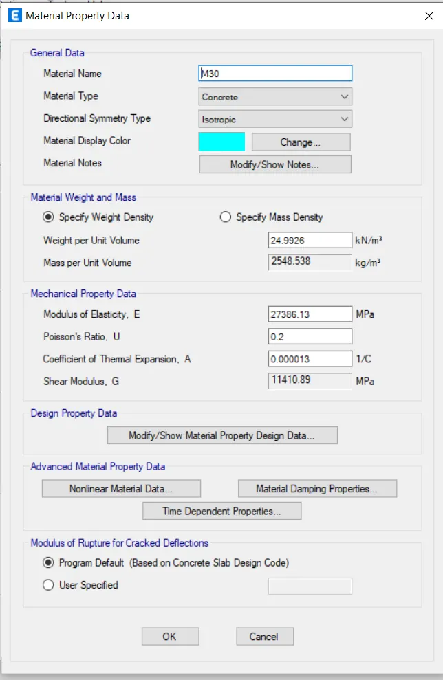
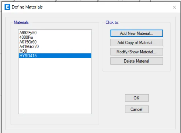
- Now to add material click on define and select material property
- And add concrete and steel material then click on ok
- To add beams and column, click on define select selection properties and select frame section
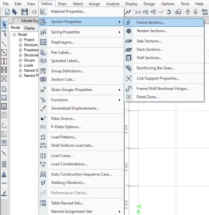
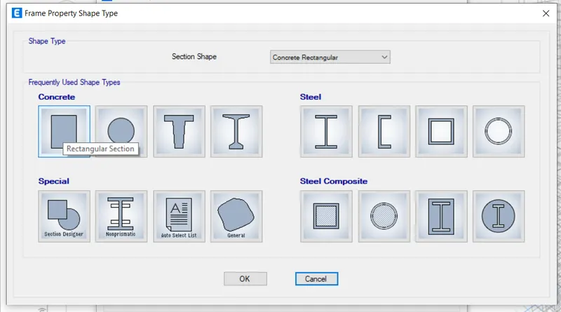
- To add beam, Select the shape from the frame property shape type
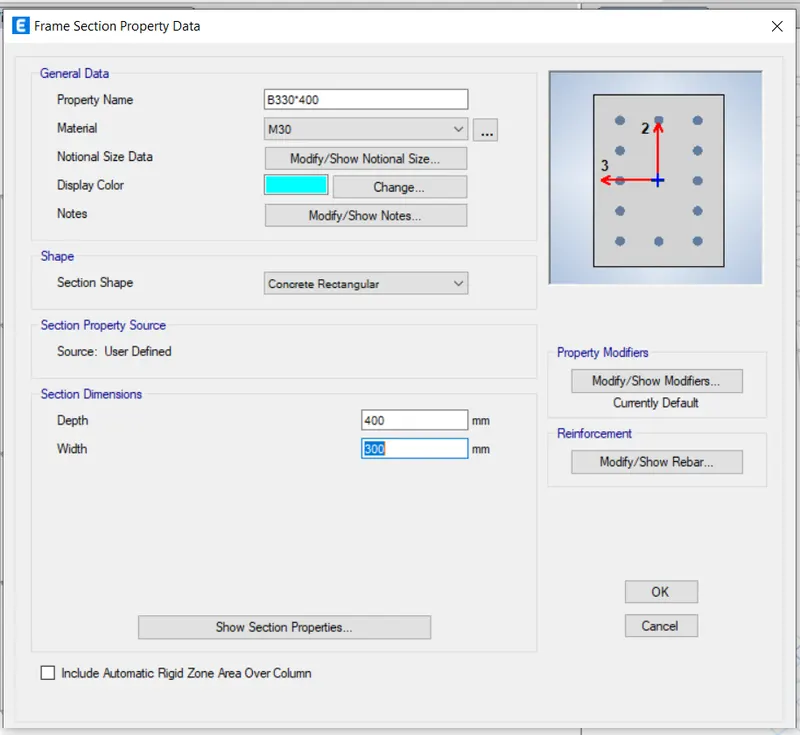
- Enter the beam details in the frame selection property data
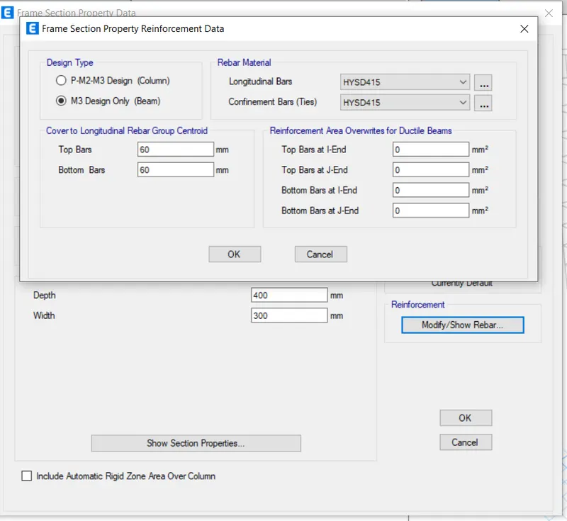
- To enter the reinforcement details click on modify/show modifers and enter the beam steel details
- To add column, select on add new property in the frame properties
- Select the shape and add column details as given
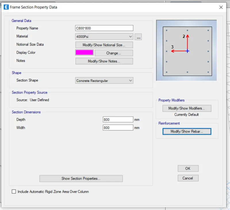
- To add reinforcement details click on modify and add the details and click on ok
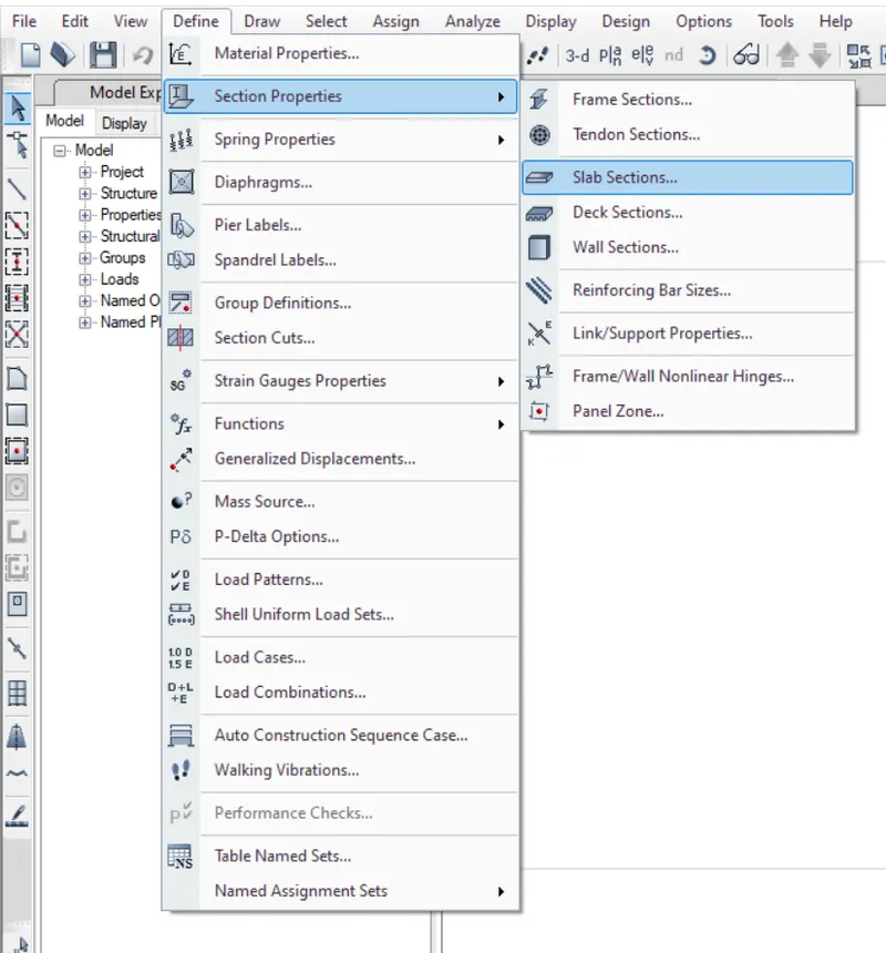
- To add slab go to define and select section properties and slab selection
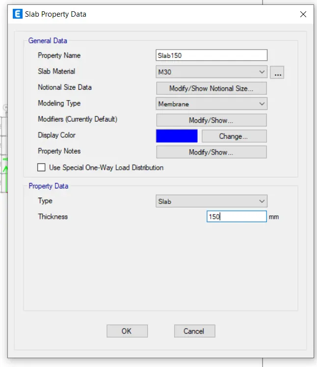
- Click on add new property and enter the details in slab property data
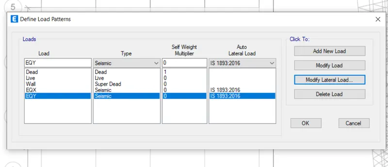
- To add load patterns click on define and selelct load patterns
- Then in define load patterns enter the loads which is needed and modify them
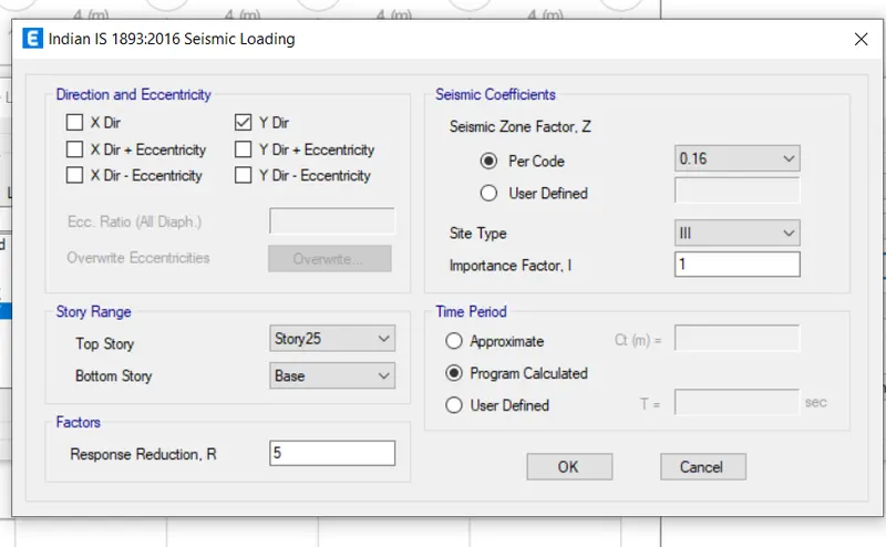
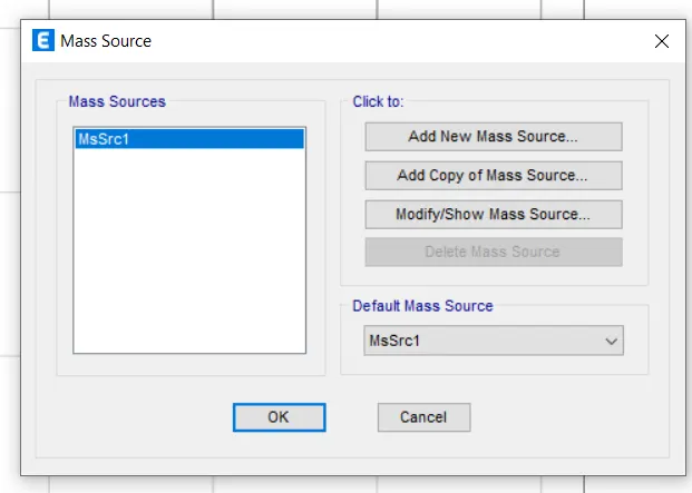
- To add mass, go to define and select mass source and enter the mass details in the mass source data
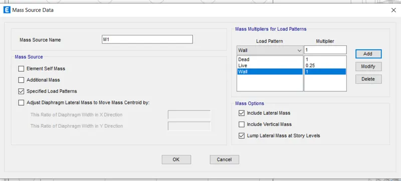
- To add load combinations go to define and click on load combinations
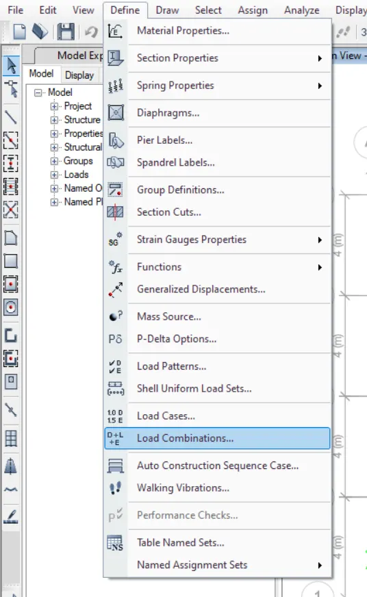
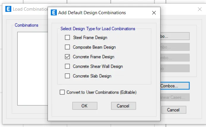
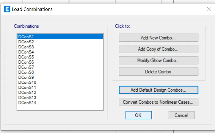
- Then a dialogue box appears in that select add default design combo and select
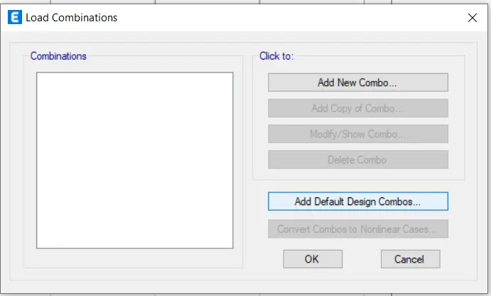
Then select concrete frame design and click on ok
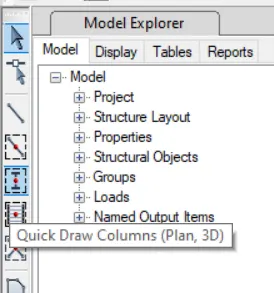
- To add created columns to the plan, select on quick draw columns icon which is present in the left side
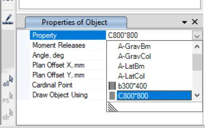
- Then in the properties option selelct the column which was created and place the columns on the grids wherever needed
- Select all storeyoption which is present in the bottom right side before placing the column
- To add beams which was created to the plan
- Click on quick draw beams and column, in the property box select the beam which was created
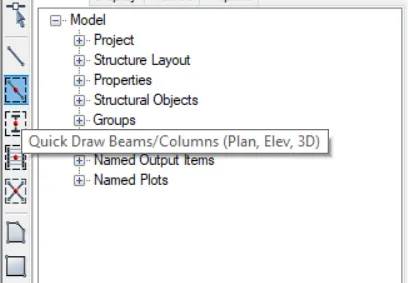
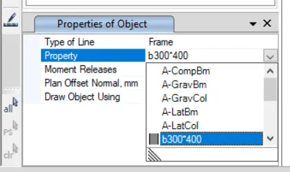
- Now place the mouse in between the column and selelct the grid the beam will be created
- To add the slab, change the storeyoption to similar storey
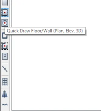
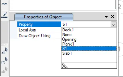
- Select the quick draw slab icon, from the property option select the slab which was created and add the slab
To assign the loads
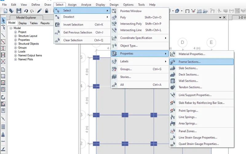
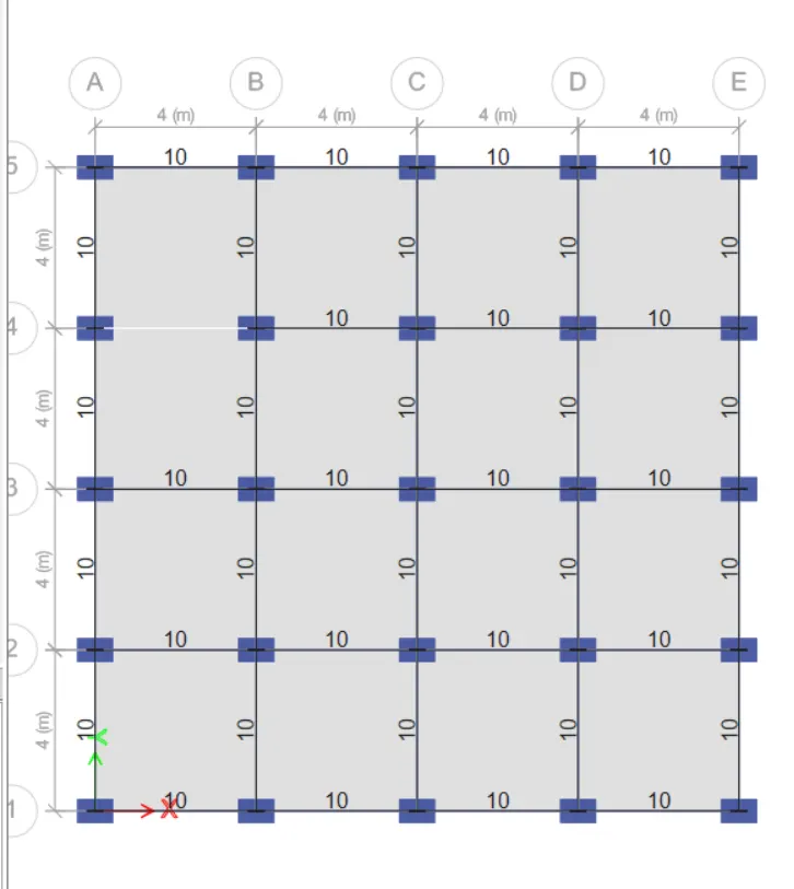
- Go to select option, click on frame selection and click on beam which was created
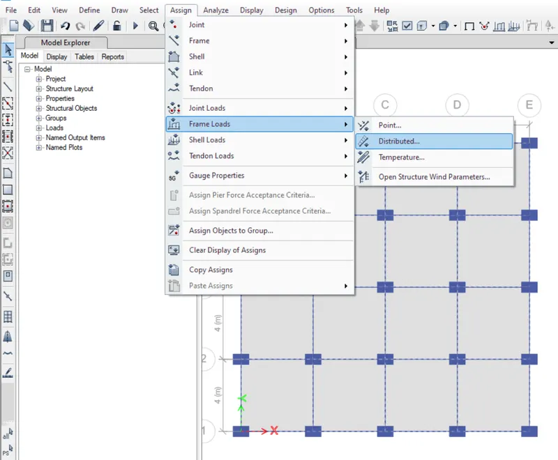
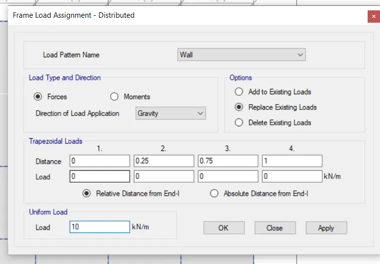
- To assign the load go to assign option and select frame load and then distributed and enter the load which is needed to apply and click on apply
-
- To add the loads to the slab
- Go to select option and click on slab section
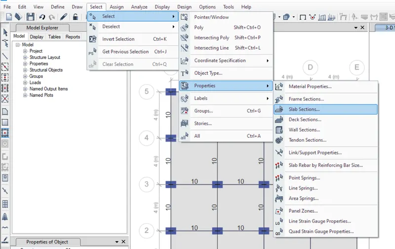
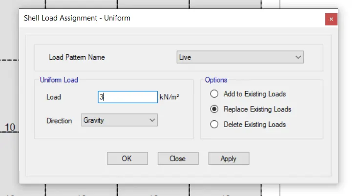
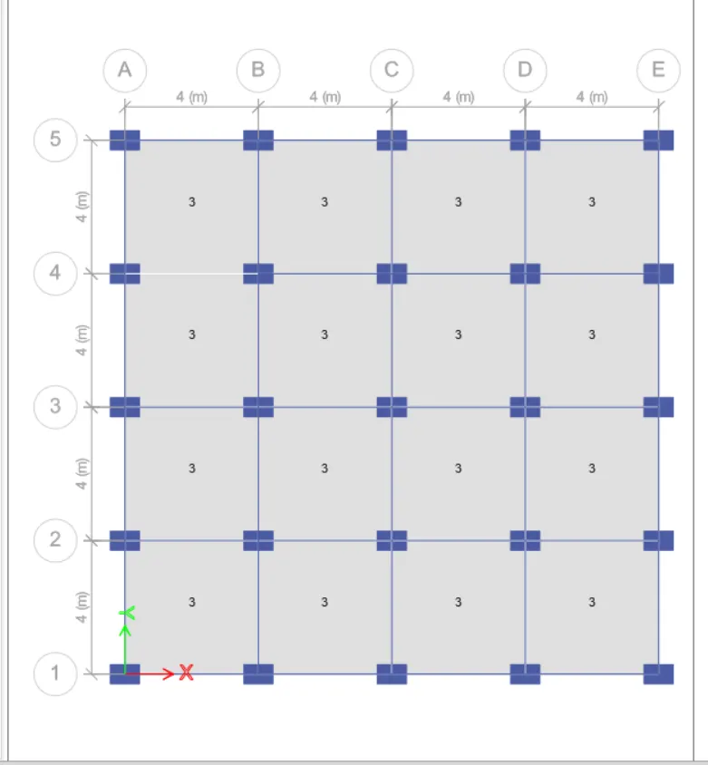
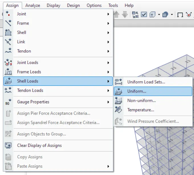
- To assign the loads to the slab, go to assign option and select shell load then select uniform
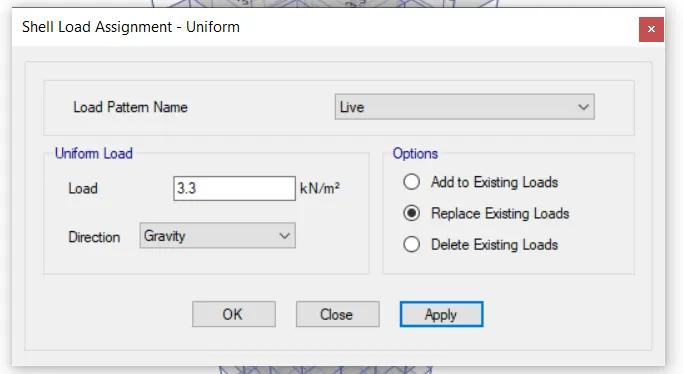
- Then enter the details of the load in the load assigments
-
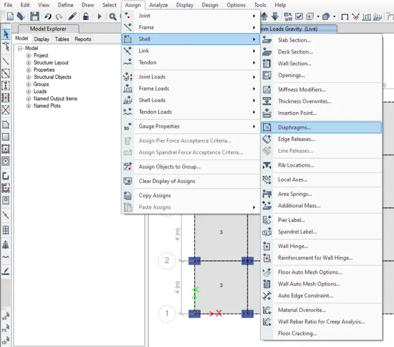
- To add the diaphram
- Go to the select option and select slab
- Then click on assign option, select shell and click on diaphram option
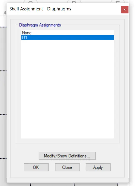
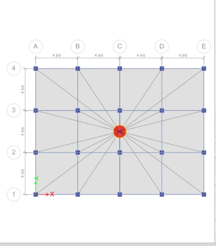
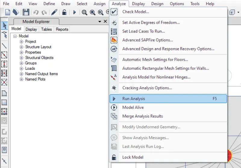
- After adding diaphram, analyze the model
- Go to analyze and select run analysis
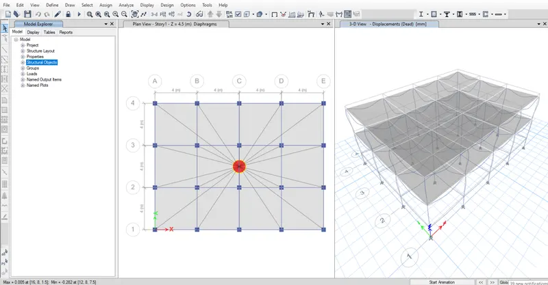
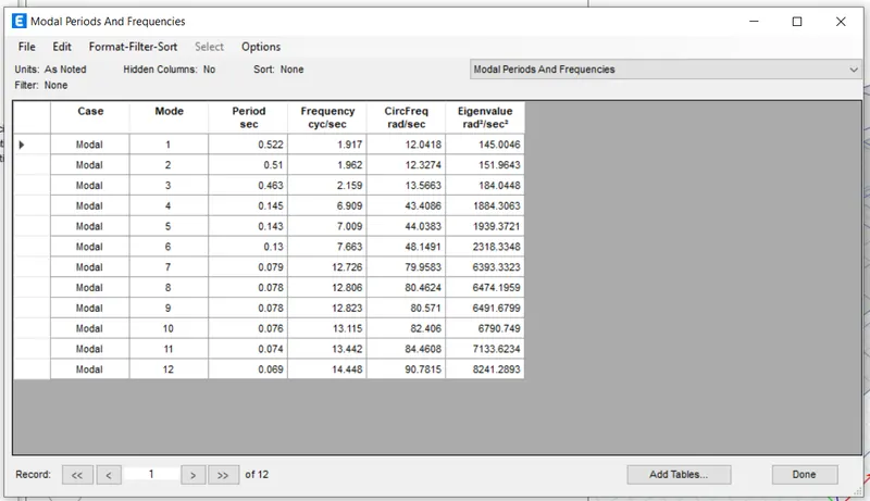
B) For 5 storey building
- From model A, go to files and click on the save as option.
- Set the destination folder and name it
- The model is set for changes as per the requirements of building b
- To edit the storey of the building, go to edit option and selelct edit storey and grid system
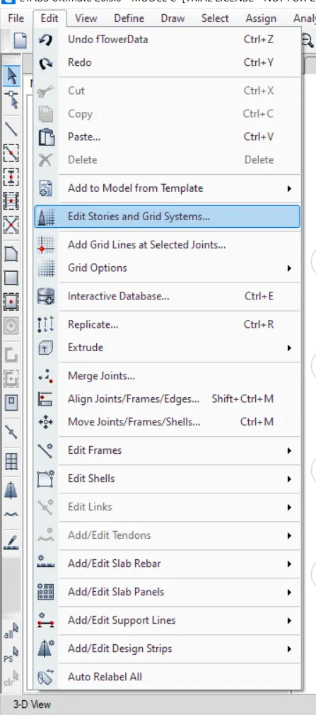
- Add 5 storey to the existing model of a building
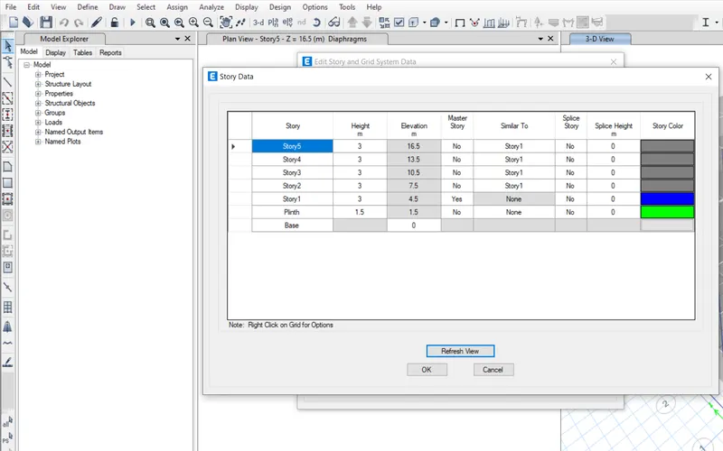
Check and analyze the model
- Now that our model is ready we need to check before running the analyze
- check is for the load assignment first
- From the bottom ribbon in ETABS, go the show frame and shell loads one at a time
- This way the model will show if the corresponding load has been assigned till the top floor
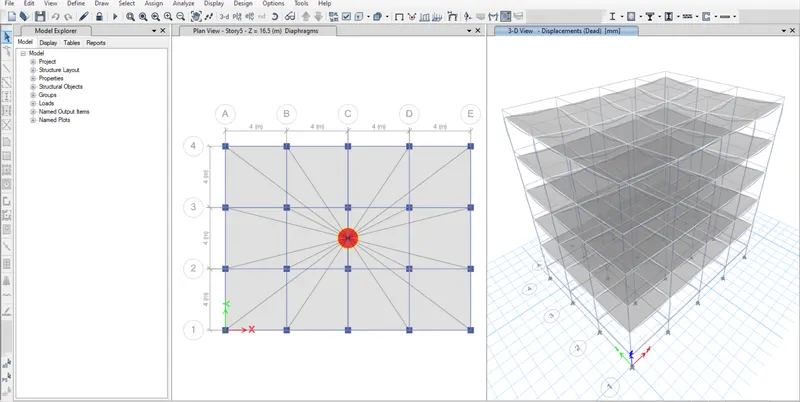
- Similarly, we need to check if the diaphragm has been assigned to the new model or not
- You can check it by going to the view settings option and checking the diaphragm visibility
- If the diaphragm is not visible, you need to select all the floors and assign the diaphragm like we did for the first model
- Now that all the checks have been made and the structure is ok, we can run the analysis
C)Building c with rectangle column orientes in X direction
- From model B, go to files and click on the save as option.
- Set the destination folder and name it
- The model is set for changes as per the requirements of building C
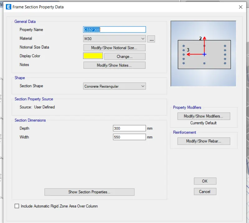
To edit the column size
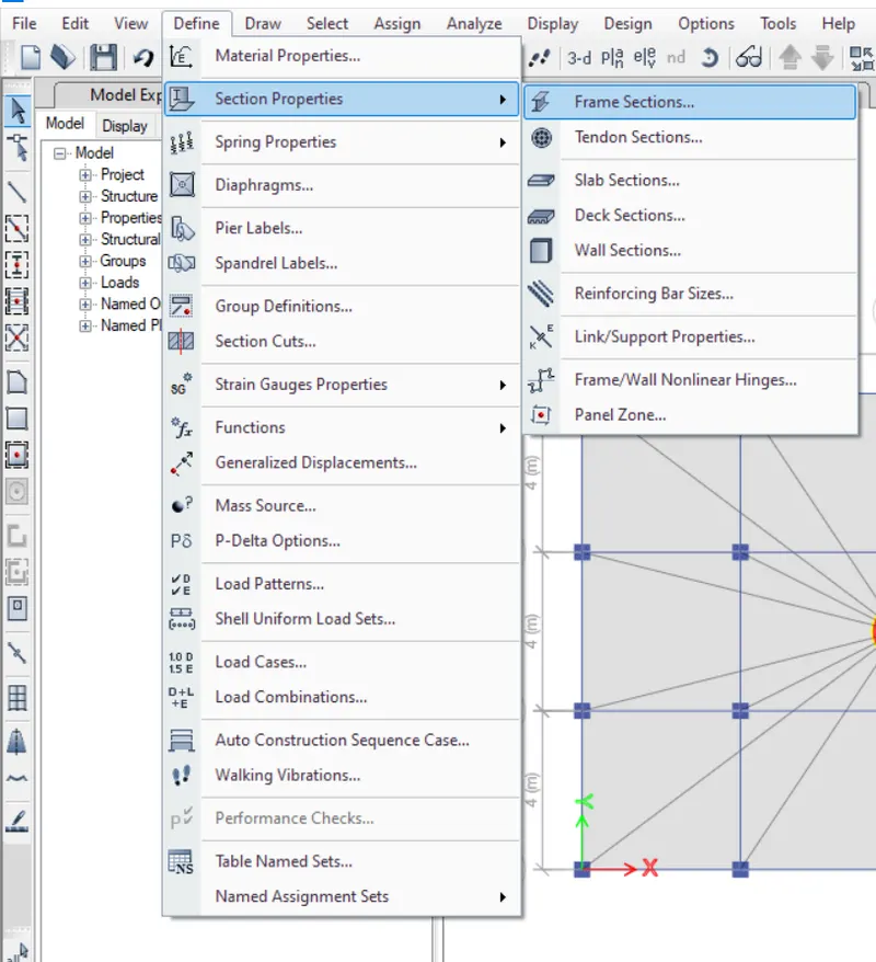
- Go to define option and select section properties and select frame section
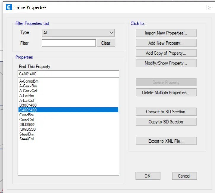
- Select the column and click on modify, modify the column as mentioned
To oriente the column in X axis
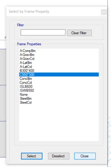
- Select the column using select option
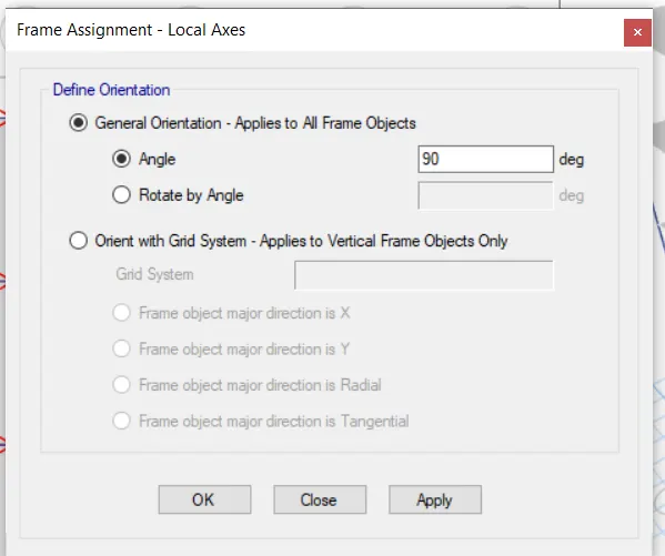
- Go to assign, frame and click on local axis and change the angle to 90
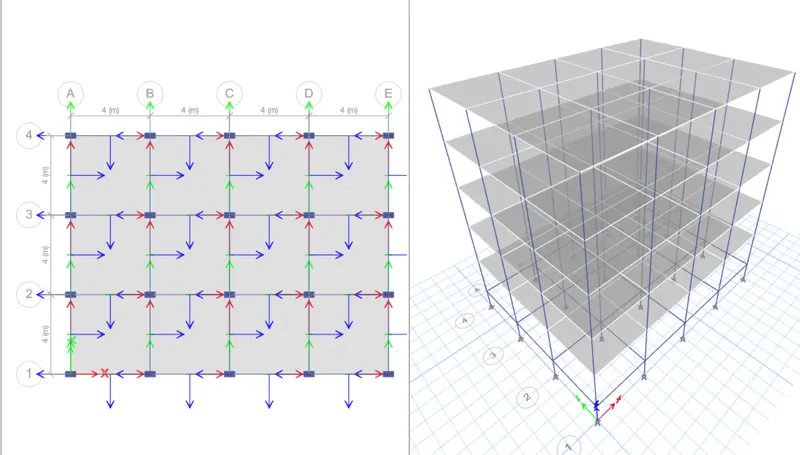
- If the diaphram is not added to the model add tyhe diaphram from the assign option
- Then run analysis of the building.
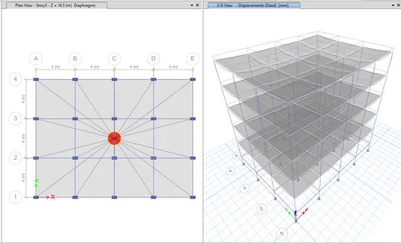
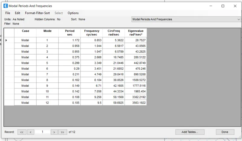
d)Building d with rectangle column orientes in Y direction
- From model C, go to files and click on the save as option.
- Set the destination folder and name it
- The model is set for changes as per the requirements of building D
- Select the column, go to the assign option,frame,local axis and change the angle to 0
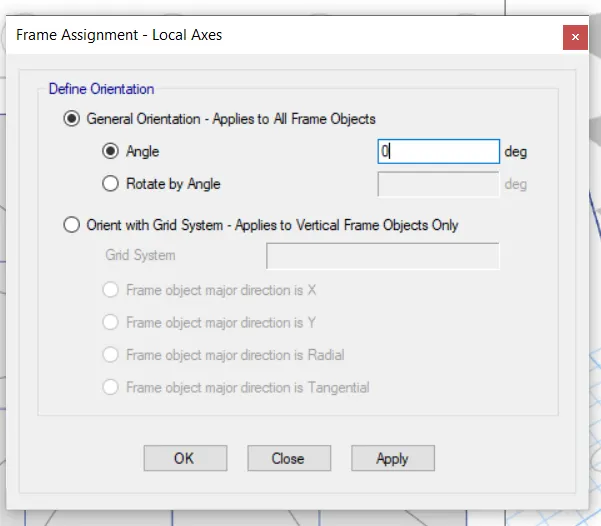
- After changing the angle run the analysis of the model
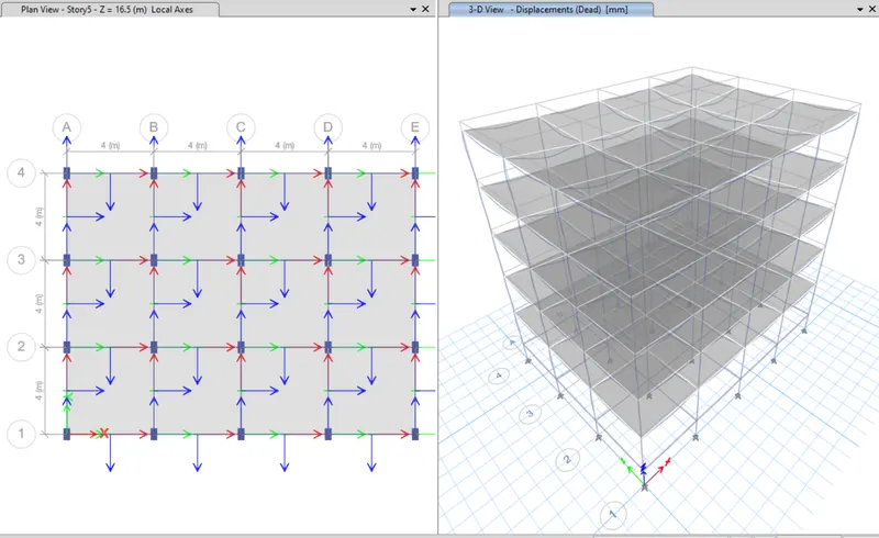
E)10 Storey building with varying column size along building height
- From model D, go to files and click on the save as option.
- Set the destination folder and name it
- The model is set for changes as per the requirements of building E
- To add more storey to the model, go to edit option and click on edit story and grid system and then add the number of storey required
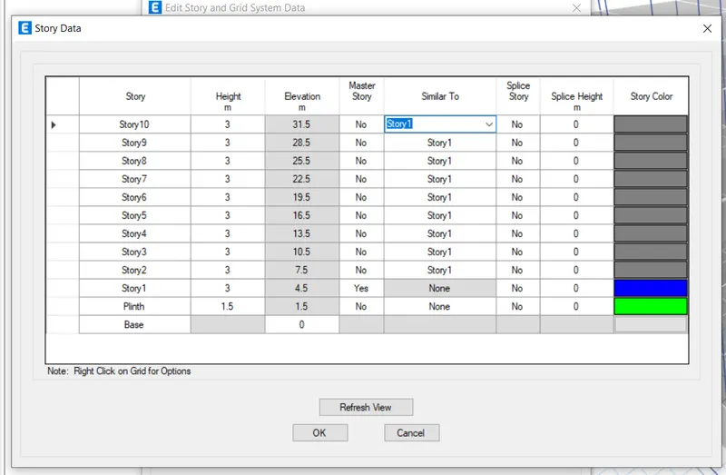
To create the column of 2 different sizes
- First change the dimension of the column which is already present, go to define, select selection properties and select frame selection
- Edit the column size as required
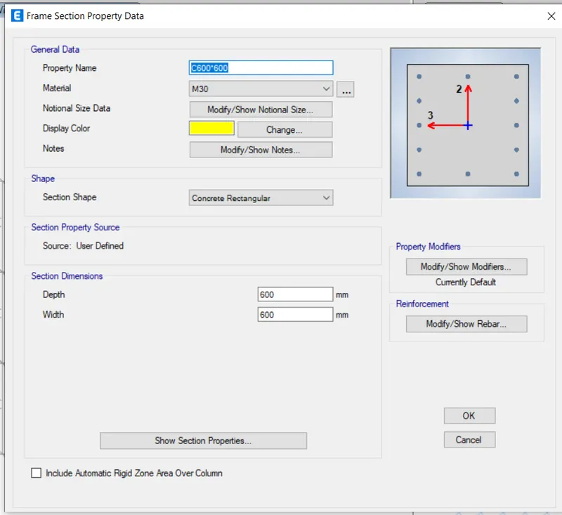
- After editng the first column create a second column
- Go to define option, select section properties, clicl on frame section, click on add new column and add the column of required dimension
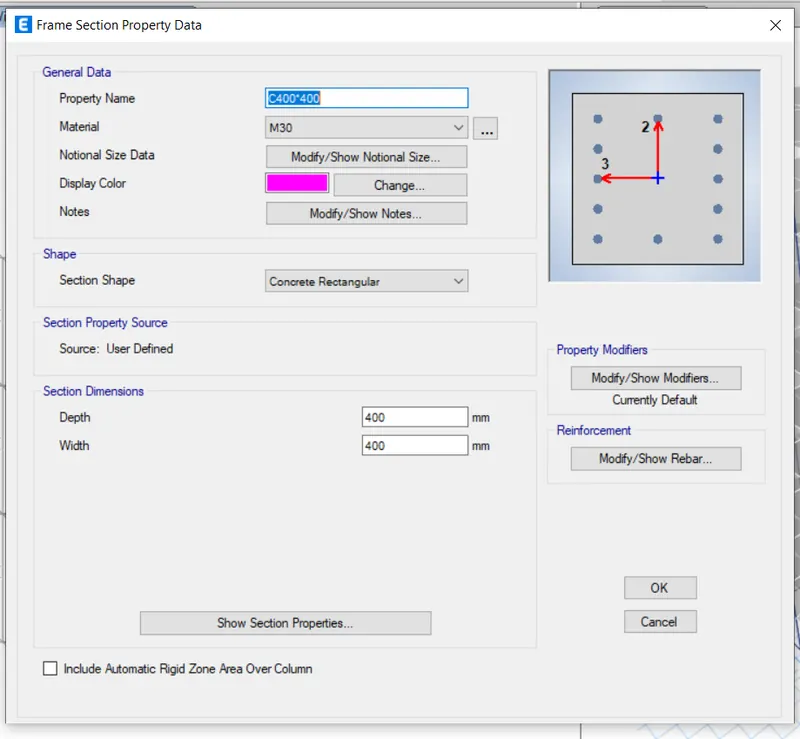
- Now to diiferent sizes of columns are created
To add the different sizes of column to two diiferent elevation
- For our modeling convience hide beams and floors
- Go to view option, select set building view limits
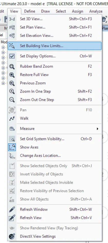
- In the dialogue box enter the view limits as shown below and click on ok
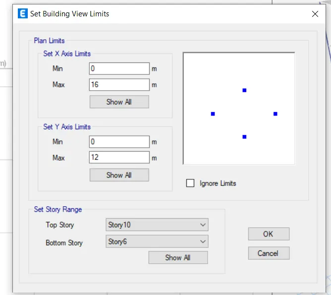
- Go to the 3d view, in the 3d view you can see that there are only the levels which was selected
- Select all the column by right click and go to assign option, select frame and selection properties and select C400*400
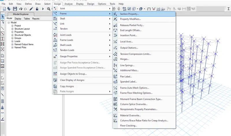
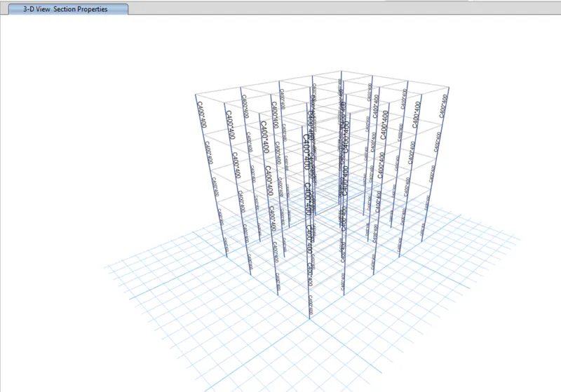
Now we can seetwo different column size has been added to two different elevation height
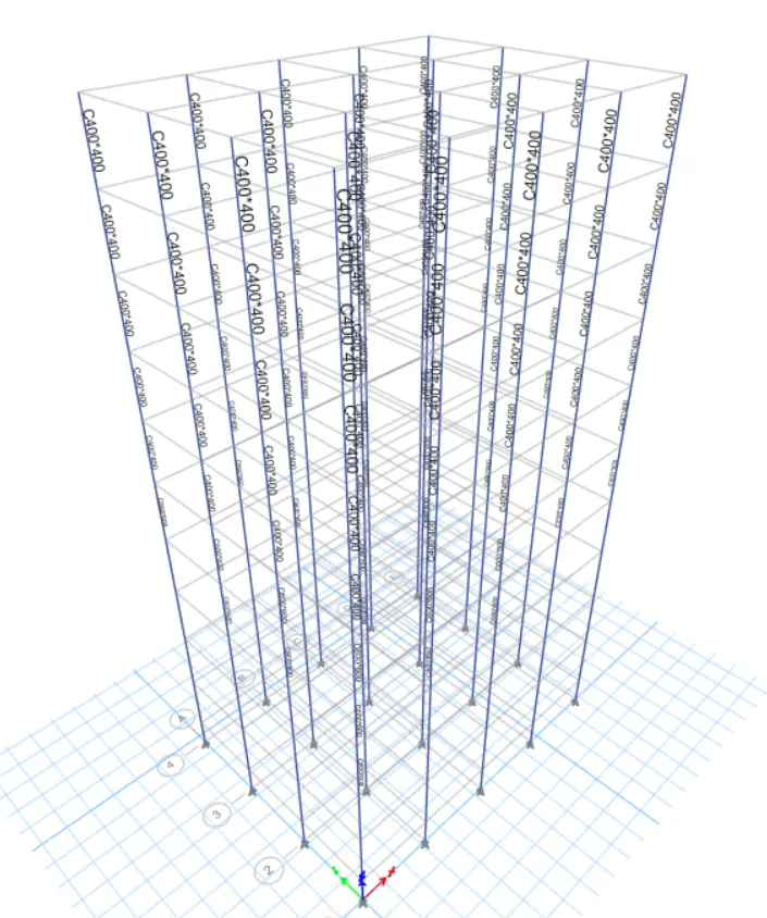
- Select the slab and assign the diaphram
- Click on run analize icon to run the analysis of the model
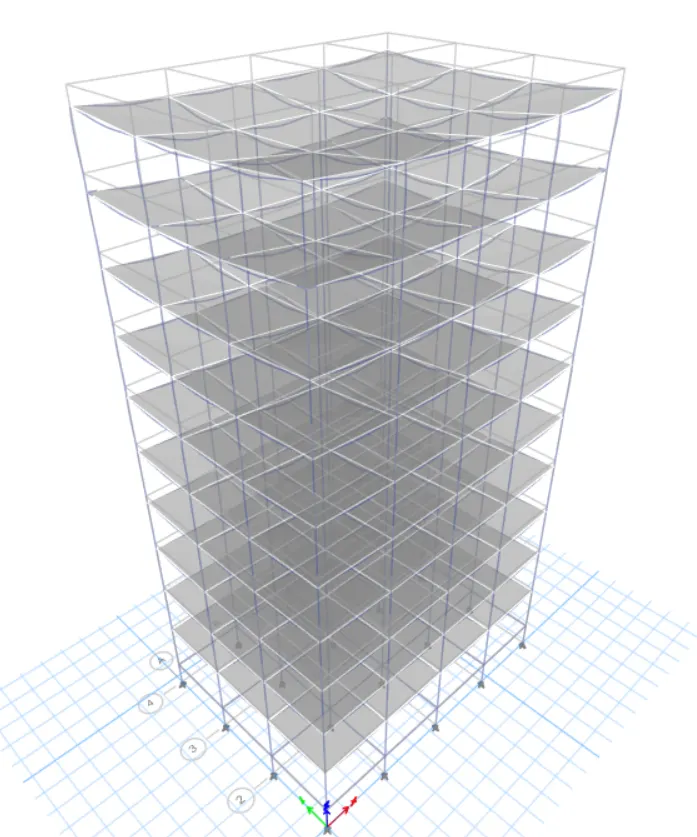
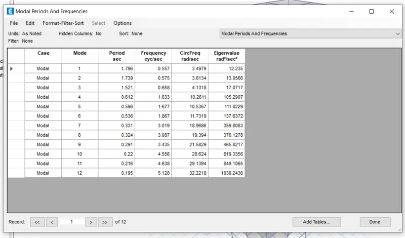
F) For 10 storey building with the column dimension of 600*600
- From model E, go to files and click on the save as option.
- Set the destination folder and name it
- The model is set for changes as per the requirements of building F
- To add column of dimension 600*600
- Select view and click on set building view limits and set the view to storey 10 to storey 6
- Then from 3d view select all the column, then go to assign,Select frame and select section property
- Select the column size of 600*600 and it will be assigned to the selected level.
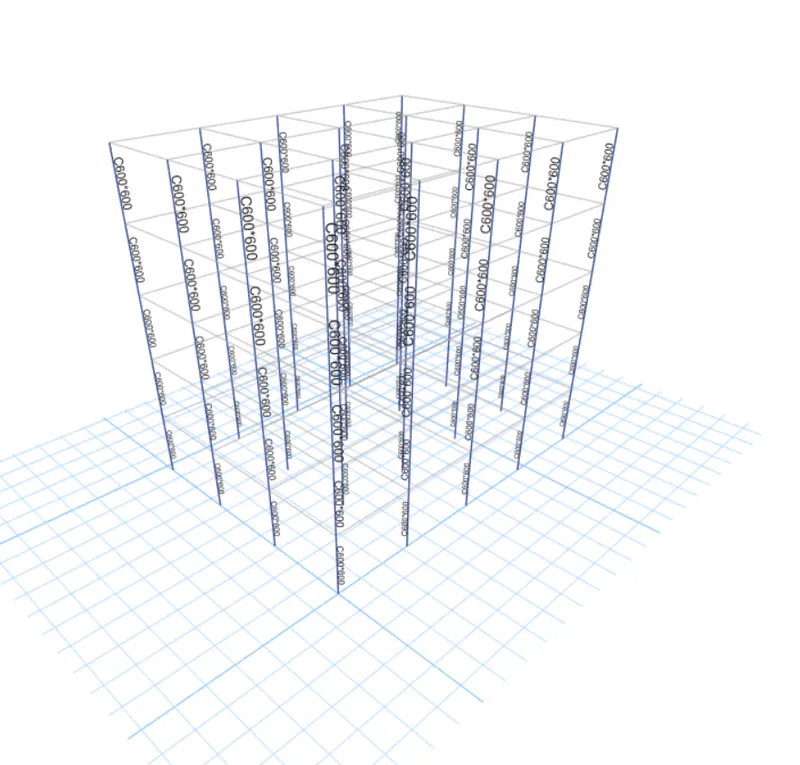
- After assigning the column, if diaphram is not added click on assign and add the diapram
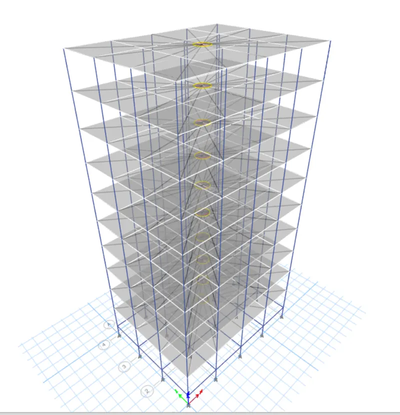
- Click on run analysis icon from the ribbon and run the analysis of the model
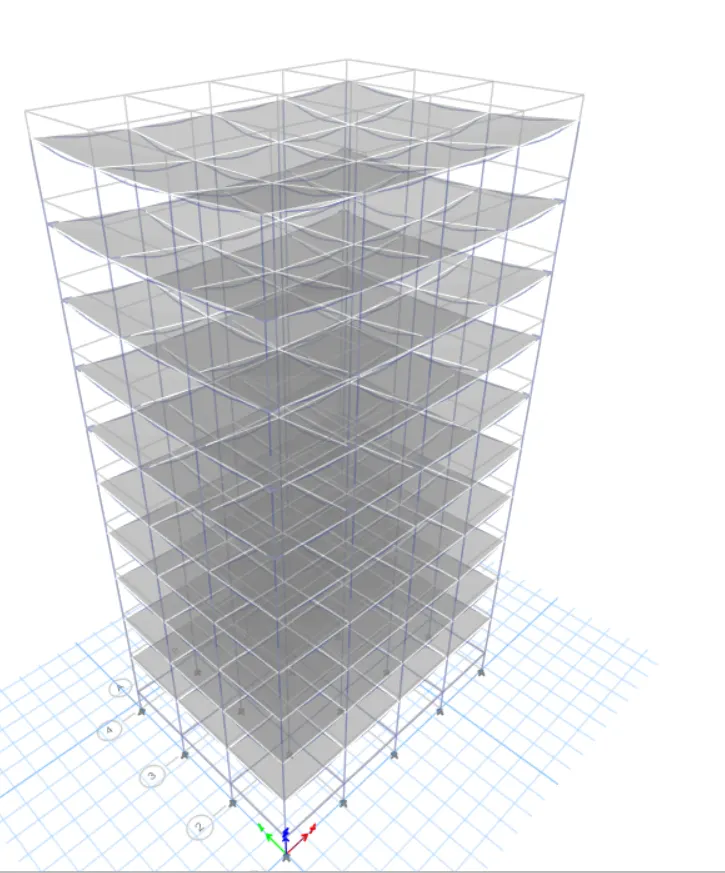
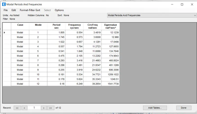
G) For 25 storey building with the
- From model F, go to files and click on the save as option.
- Set the destination folder and name it
- The model is set for changes as per the requirements of building G
To add 25 storey in a model
- Go to edit, click on edit, select edit storey and grid system and add the storey upto 25
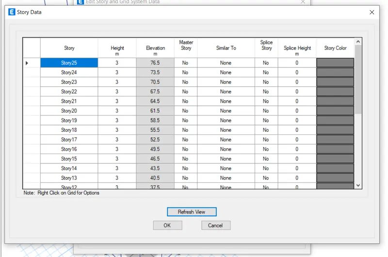
To assign columns to mentioned elevation
First let us assign the column size of 400*400 to upper 5 storeys
- Go to view option, select set building view limits as 5 storey
- In the dialogue box enter the view limits as shown below and click on ok
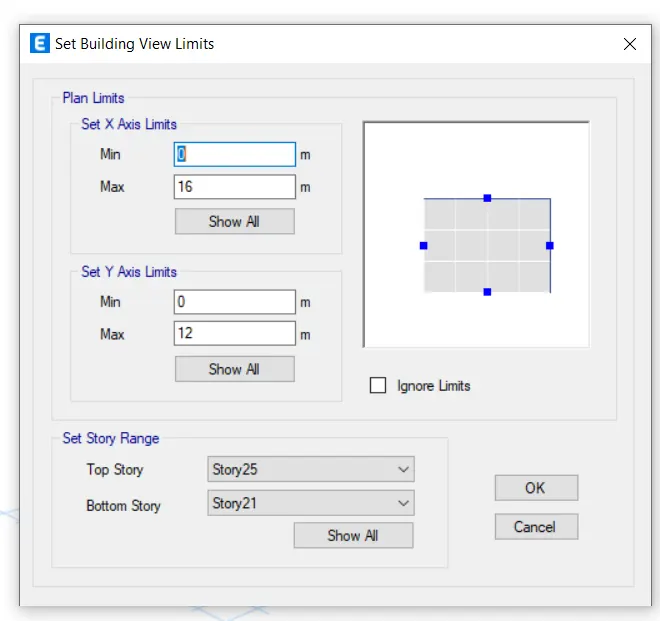
- Select only columns and assign the column of 400*400 for the top 5 storeys
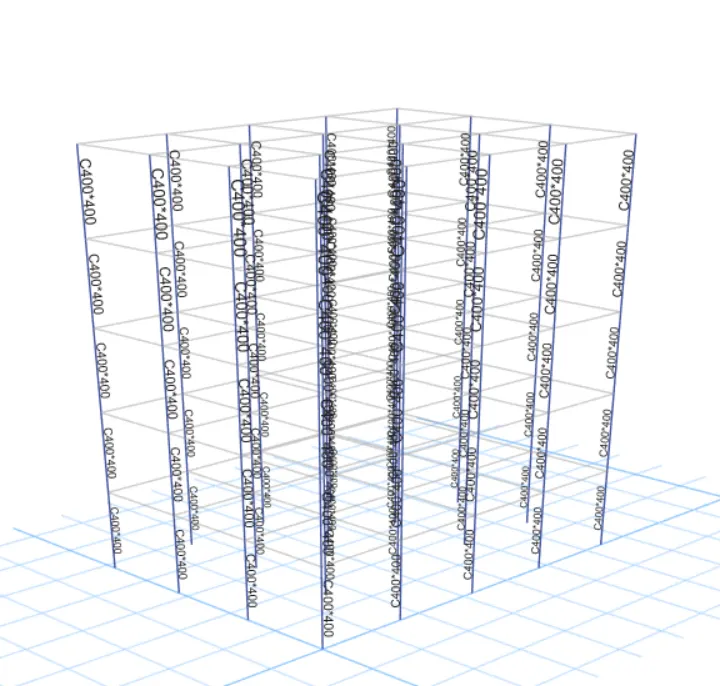
To assign columns to middle 10 storey
- Go to view option, select set building view limits as 10 storey
- In the dialogue box enter the view limits as shown below and click on ok
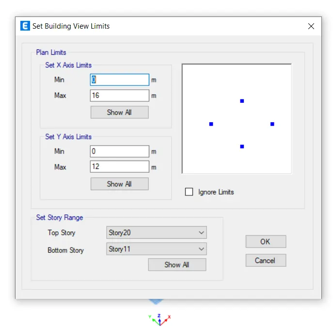
- Select the column and assign the column of the size 600*600
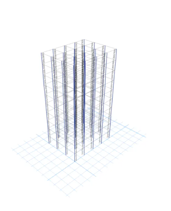
To assign columns to bottom 10 storey
- Go to view option, select set building view limits as 10 storey
- In the dialogue box enter the view limits as shown below and click on ok
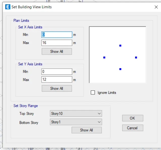
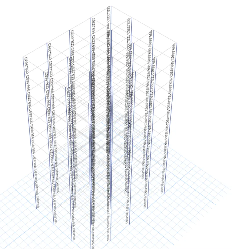
- After assigning the column, if diaphram is not added click on assign and add the diapram
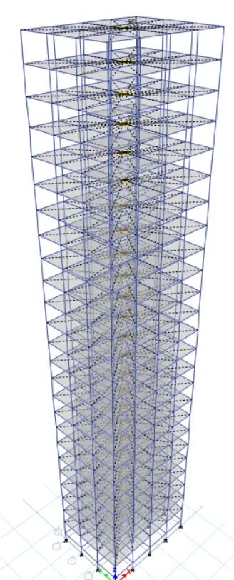
- Click on run analysis icon from the ribbon and run the analysis of the model
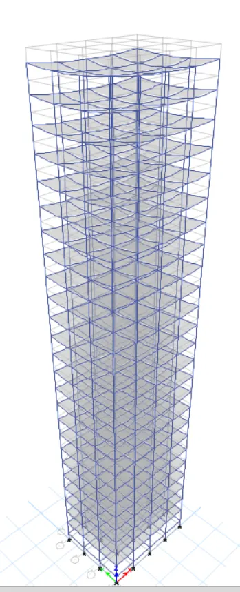
H) For 25 storey building with the column dimension of 800*800
- From model G, go to files and click on the save as option.
- Set the destination folder and name it
- The model is set for changes as per the requirements of building H
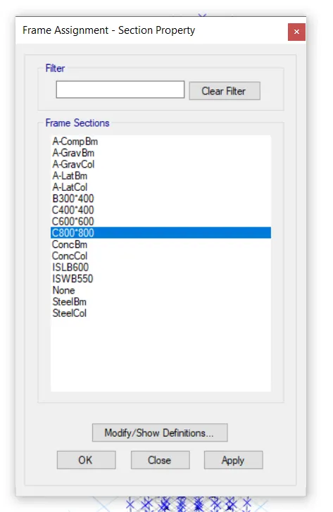
- Select all the column and assign the column of dimension 800*800
- To assign the column go to assign option and select frame and section property
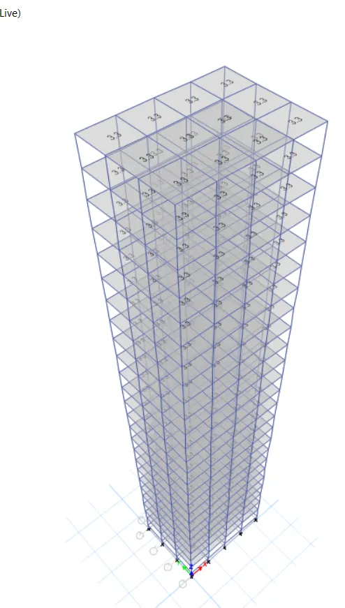
J) For 25 storey building with imposed mass of 10% larger than Building H
- From model H, go to files and click on the save as option.
- Set the destination folder and name it
- The model is set for changes as per the requirements of building J
To assign mass of 10%
- Go to assign option, select shell load and uniform and assign the value of 10%
K) For 25 storey building with imposed mass of 10% larger than Building H
- From model J, go to files and click on the save as option.
- Set the destination folder and name it
- The model is set for changes as per the requirements of building K
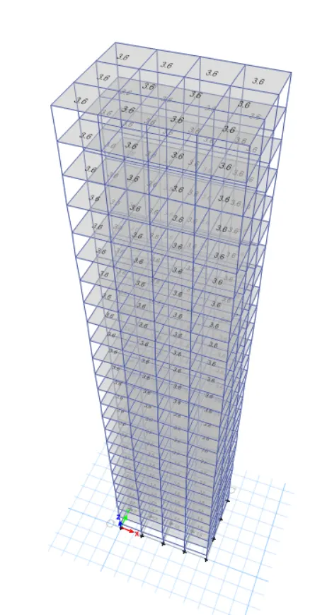
To assign mass of 20%
- Go to assign option, select shell load and uniform and assign the value of 20%
Result:
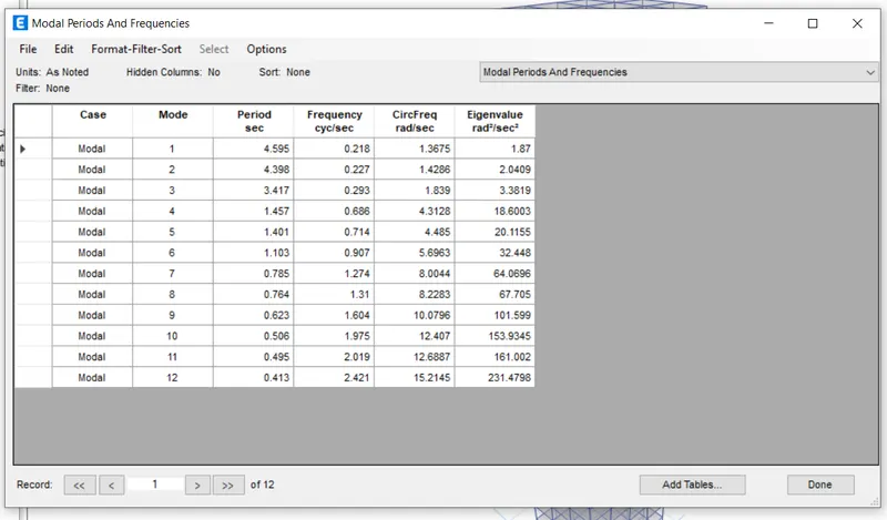
Effect of stiffness on time period
- Building E (10 storey with varying column size)= 1.79s
- Building F (10 storey with uniform column size)= 1.8s
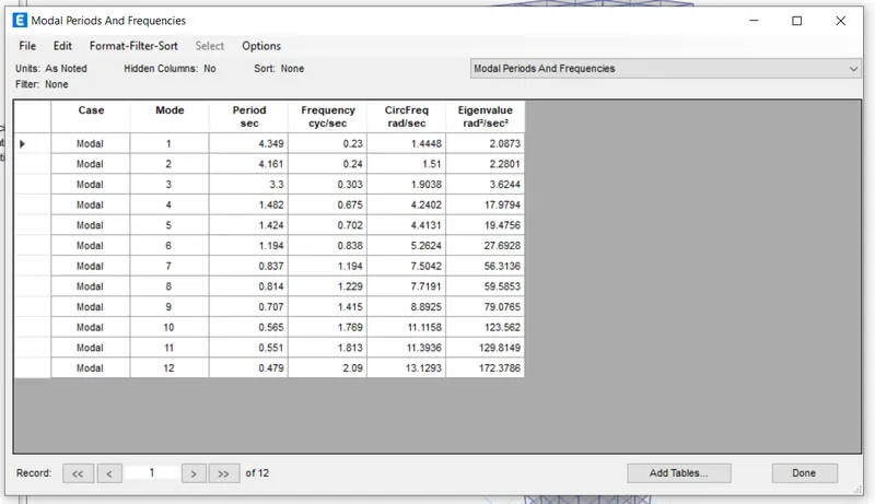
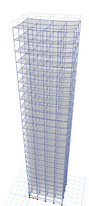
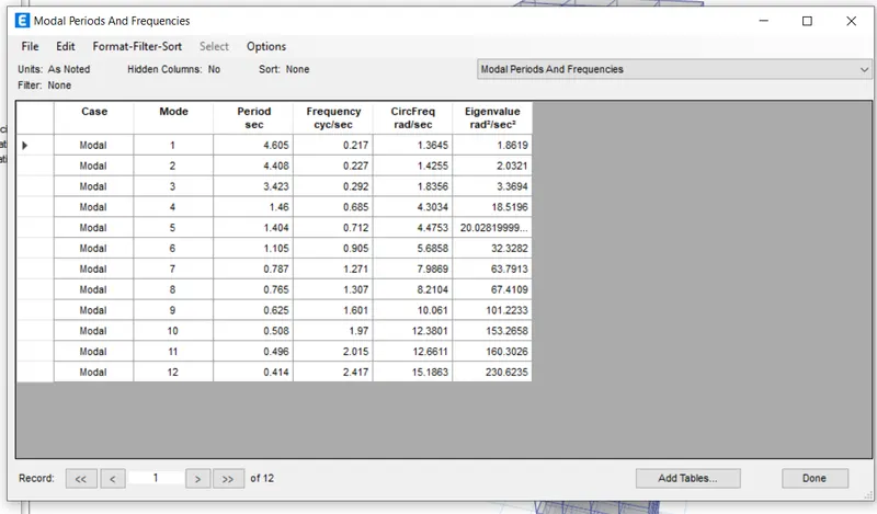
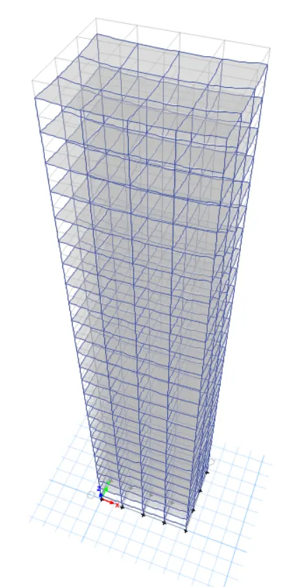
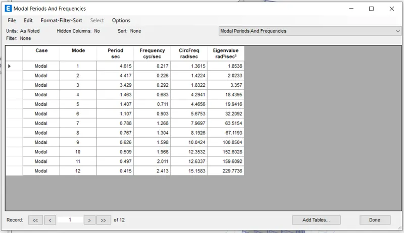
- Building G (25 storey with varying column size)= 4.34s
- Building H (25 storey with uniform column size)= 4.5s
Conclusion: For buildings E and F, varying column design doesn't make a big difference as there are only five stories. However, we can see that for buildings G and H, the consistent column size throughout the structure causes a more natural period. It can be concluded that providing larger columns at the base and then reducing the size on top floors helps control the natural period for tall buildings.
Effect of mass on time period
- Building H (25 storey with 3 KN/sq.m imposed load)=4.5s
- Building J (25 storey with 3.3 KN/sq.m imposed load)=4.6s
- Building K (25 storey with 3.6 KN/sq.m imposed load)=4.6s
Conclusion: Since mass is directly proportional to lateral force so there will be increase in the time period of the building
Effect of building height on Time period
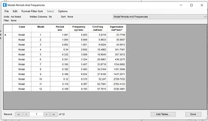
- Building A (2storey)=0.52
- Building B (2storey)=1.08
- Building F (2storey)=1.8s
- Building H (2storey)=4.5s
Conclusion:
As indicated from the above table, the natural period is directly proportional to the building height.
Effect of column orientation on time period
- Building B (all floors column size 400*400)=1.08
- Building C (all floors column size 550*300) oriented in X direction=1.17
- Building D (all floors column size 300*550) Oriented in Y direction=1.1
Conclusion: When the column is orinted in a particular direction be it X or Y, the lateral displacement in that particular direction will be less than that in the other direction which has a lesser column length.
Effect of flexural stiffness of structural elements on mode shapes (for building B)
- Flexural stiffness of beams close to nil (zero inertia)=2.74
- Full flexural stiffness of beams (regular)=1.08
Conclusion:If we dont consider the stiffness of the structure we will be get the double time period then the regular one which has stiffness
Effect of axial stiffness of vertical member on mode shape (for building H)
- Axial cross section for columns is close to nil(Zero axial area)=6.11
- Full axial cross section for columns(regular)=4.5
Conclusion: As the axial stiffness of columns decreases, the fundamental natural period of the building increases.