Project 1_Comparative study of different storey buildings for Seismic forces
Aim: To model ten different buildings having different conditions as given. To compare and study the modelled different storey buildings for Seismic forces
Introduction:
The ten buildings named from A to K are given with conditions as mentioned below
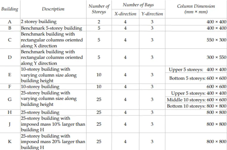
For all the buildings
Structural Element Sizes
- Beams : 300 × 400 mm
- Slab : 150 mm thick
Material Properties
- Grade of Concrete : M30
- Grade of Steel Reinforcement Bars : Fe 415
Loading
- Dead Load on beams from infill wall : 10 kN/m
- Live load on floor : 3 kN/m2
Buildings are assumed to be pinned at base and Bay length in each plan direction is 4m (Centre to Centre)
Procedure:
a) For Building A
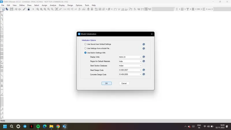
1. Open Etabs software and choose new model
2. Choose use built-in settings and give the units, codes accordingly as shown
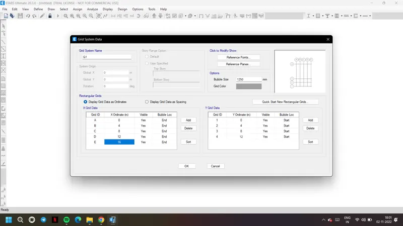
3. Now we get grid system tab, choose display grid data and as per the plam give 5 grids in x direction
4. And 4 grids in y-direction with 4m distance as shown
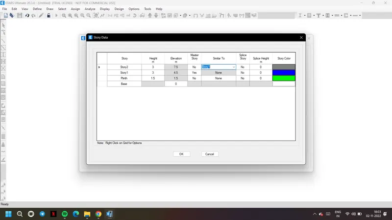
5. Now go to storey data and give plinth beam with 1.5m height and other storey with 3m
6. Keep the story 1 as master story and keep it as similar story for all other stories as shown
7. Now delete all other stories and keep only story 2 and make it similar to story 1
9. After closing the tab, the building is created in this way with given grids and story data
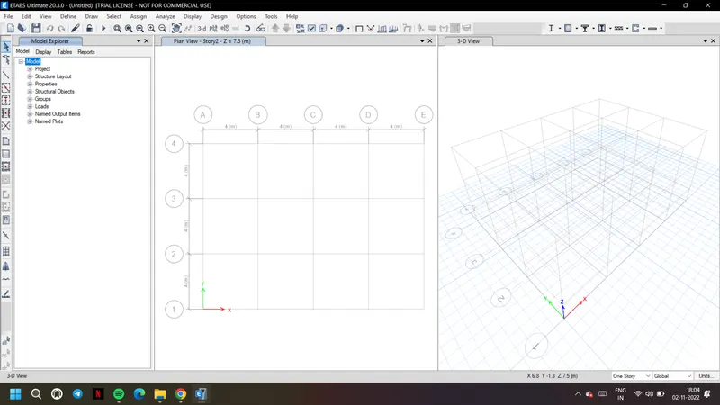
10. Now to assign material property, go to material properties from define tab
11. Choose concrete of grade 30 and rebar steel of Fe415 as mentioned
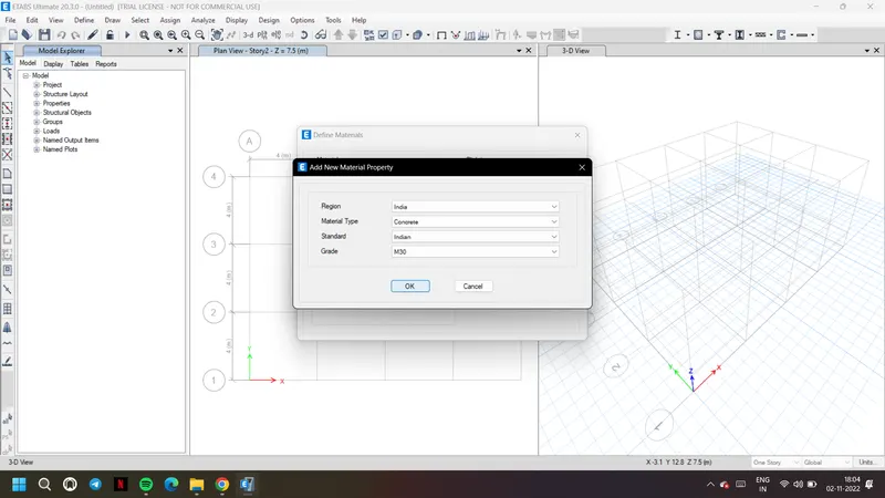
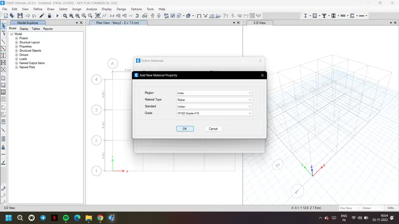
12. Now go to section properties and frame sections to define frames
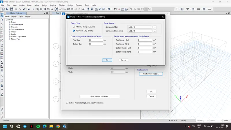
13. Define the beam, B300x400 and modify to set rebar settings and save
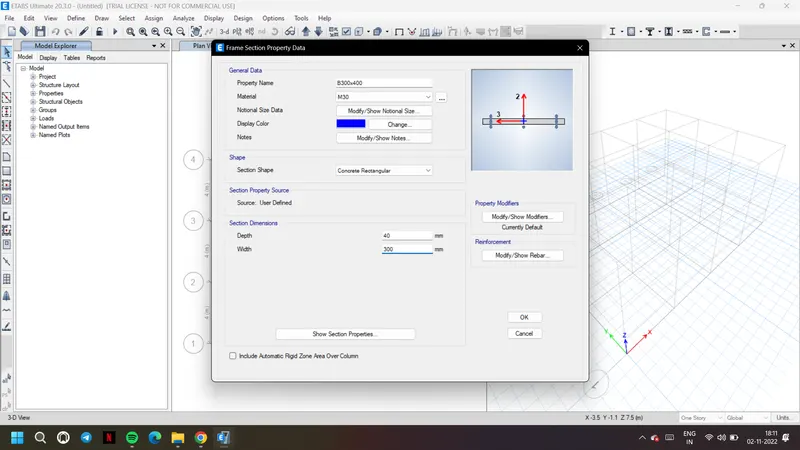
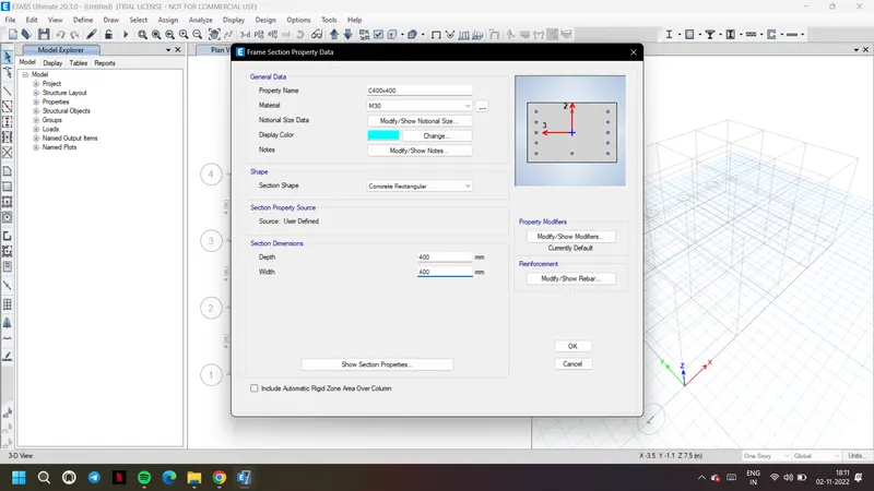
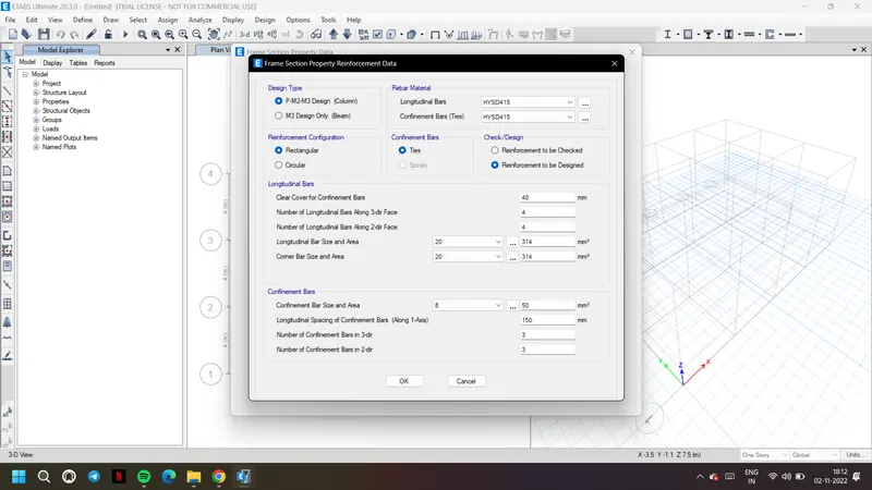
14. Similarly create frame column, C400x400 and give its properties and rebar as Fe415
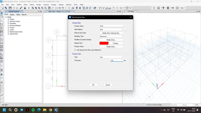
15. Now for slab go to slab sections and create a slab with 150mm thickness
16. Now go to load patterns from define tab and add the given loads accordingly
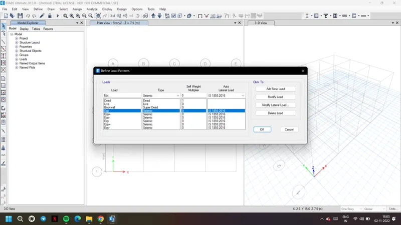
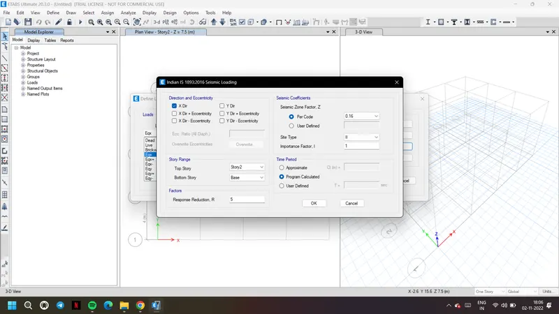
17. For lateral loads, go to modify lateral load and set them accordingly as shown
18. As given seismic zone is II and soil type is II
19. Now go to mass source and set the load patterns accordingly as per code
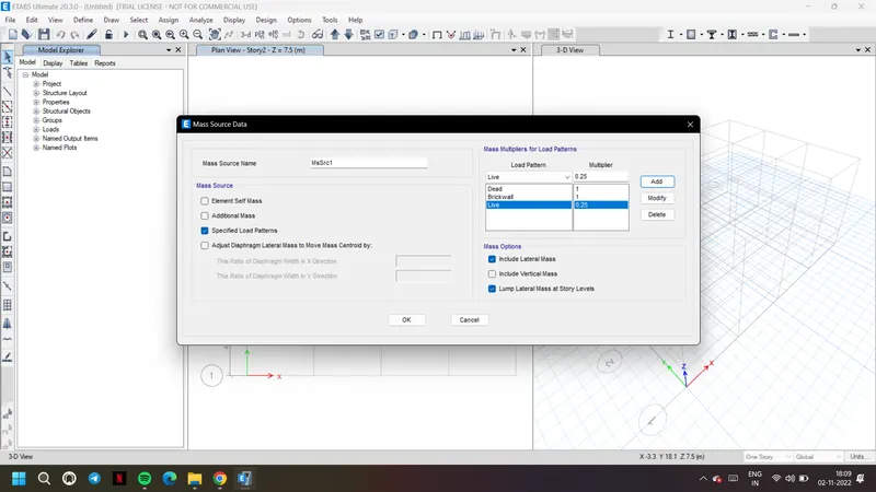
20. Live load being 25 percent and dead, brick load with 100 percent mass
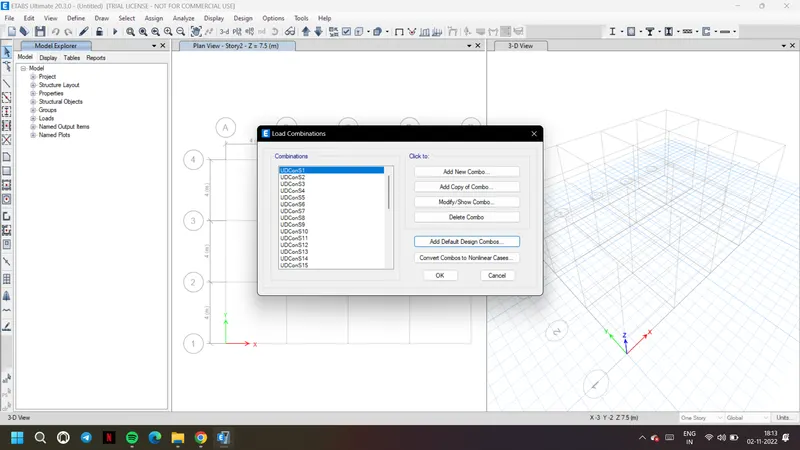
21. Go to load combinations from define tab and choose add default design combinations
22. As per the selected code and load patterns, we get the load combinations
23. Now to draw columns, choose quick draw columns and choose property as column C400x400
24. Choose option all stories as we need columns at each and every storey
25. Place the columns at each grid as shown as per the plan
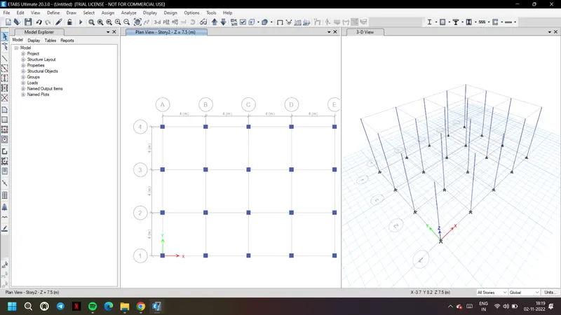
26. Similarly now choose beam and place them as shown connecting the columns
27. There is also an option to replicate the created frames using replicate from edit tab
28. Replicate the beams to all other bays as shown using replicate option
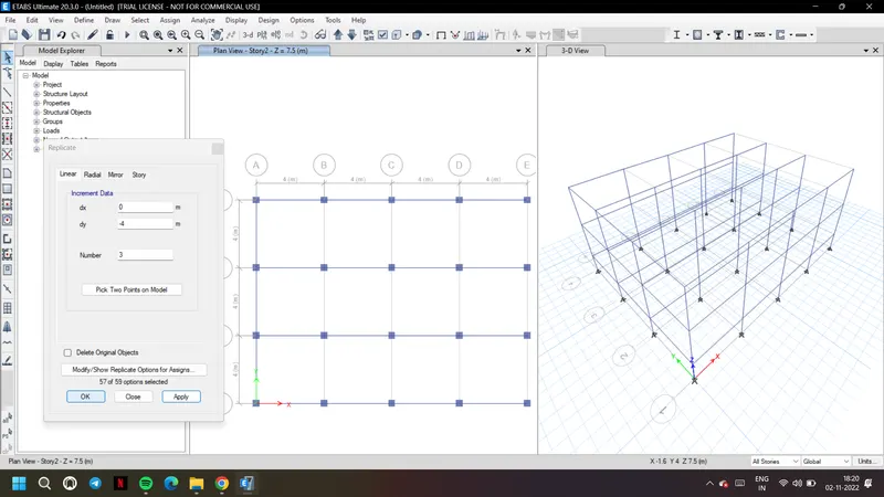
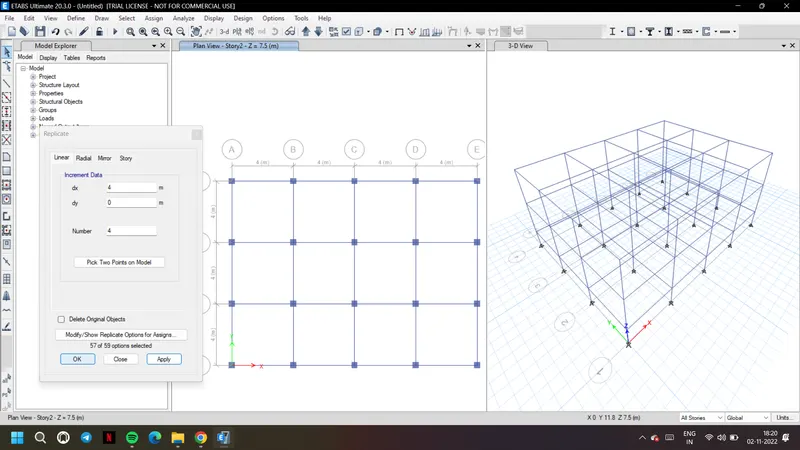
29. Now open the plan view of story 1 and choose similar stories to create slab for all the stories
30. Choose quick draw slab and choose S150
31. Place the slab in story 1 so that they will replicate in all other similar stories
32. The 3D view after creating beams, columns and slabs
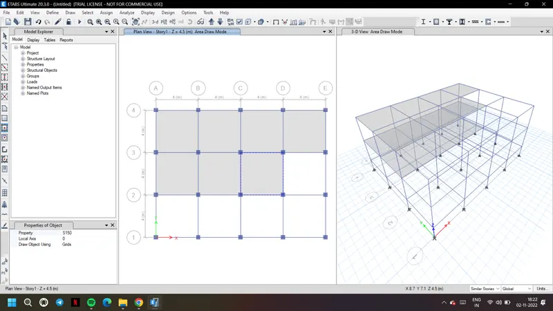
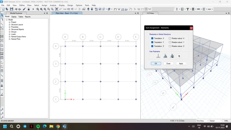
33. Now open the base plan, go to assign and restraints and choose pinned joints as mentioned
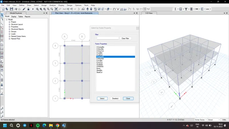
34. Now to apply loads, go to select and select frame sections to select only the beams
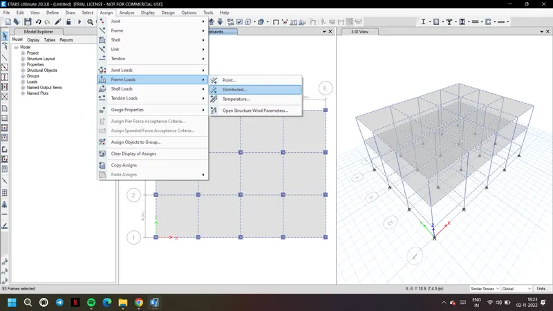
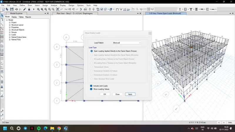
35. Select the beams, go to assign framed loads and distributed
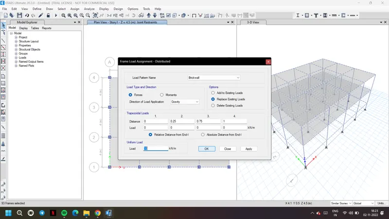
36. Choose brick wall and give it as 10kN/m as given
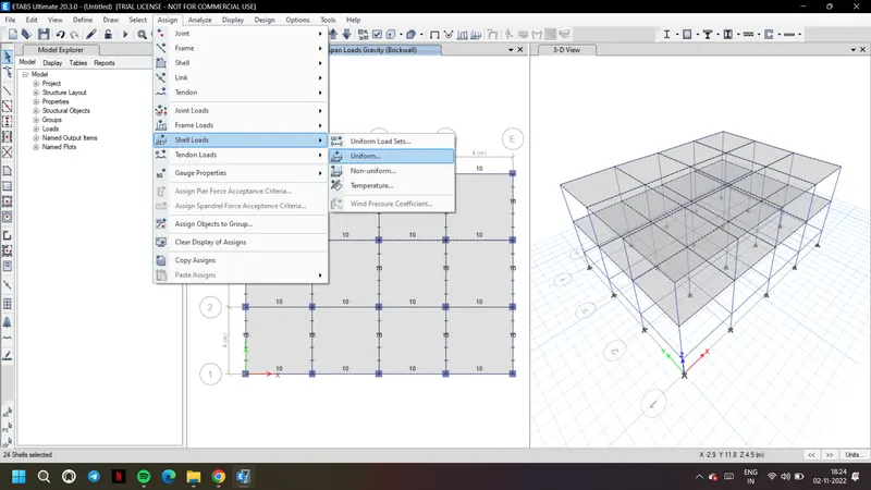
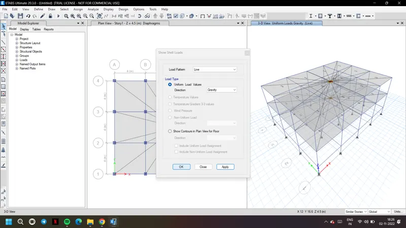
37. Now from slab selections select slab. Go to assign shell loads, uniform.
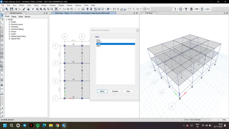
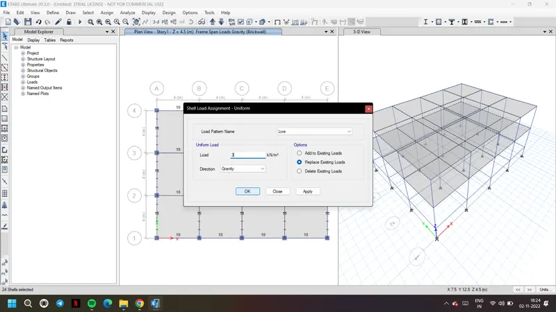
38. Apply load of 3 kn/m^2 live load on slab
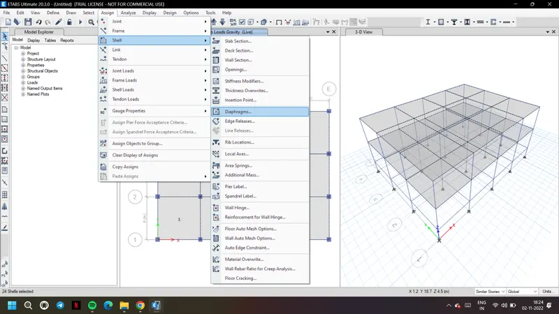
39. Now again select slab, go to assign tab shell and diaphragms
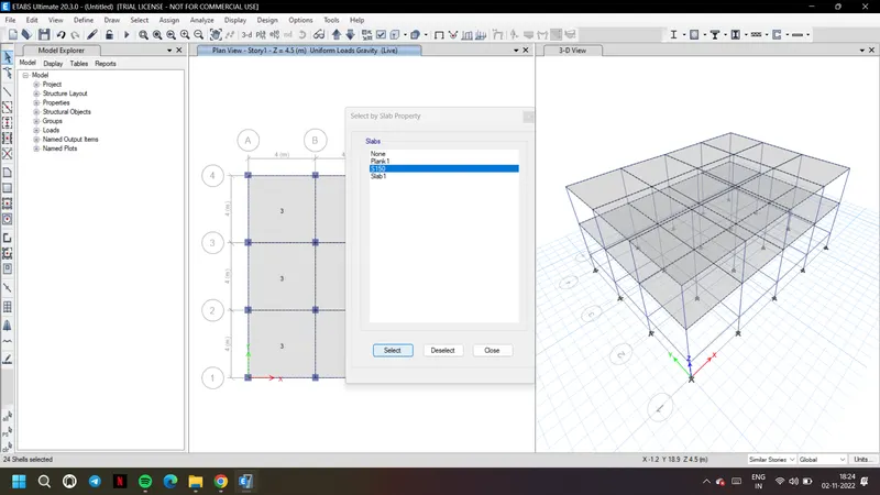
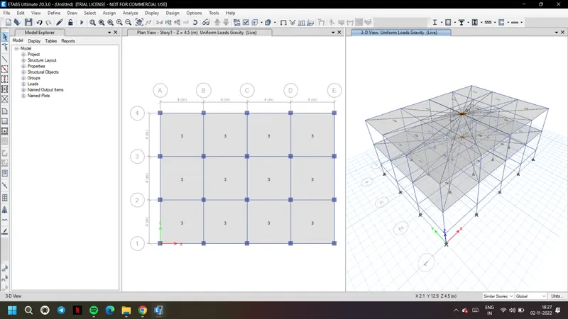
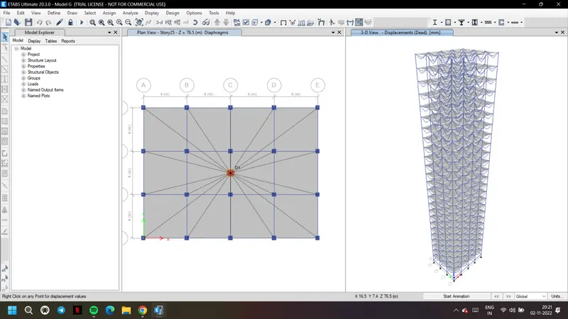
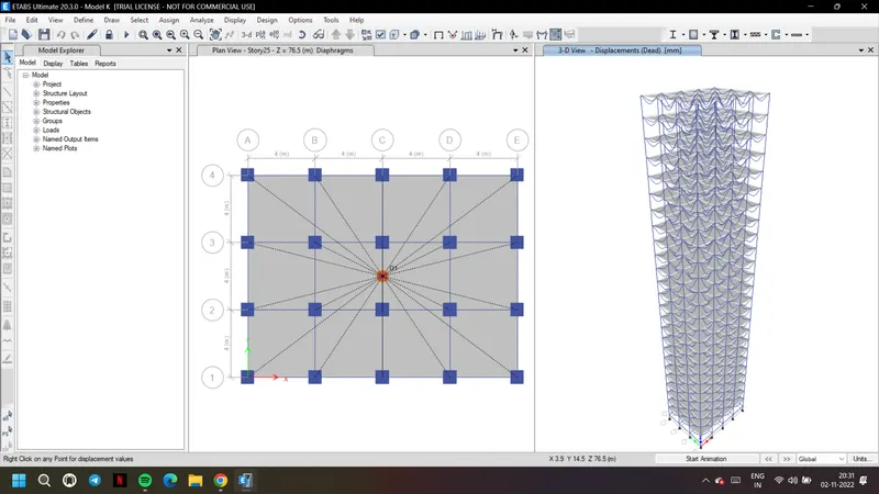
40. Choose D1 and apply to get the center of mass of the building as shown
41. Before analyzing the structure go to check model from analyze tab as shown
42. It is clear that no overlapping or missings frames in the designed structure
43. Now choose run analysis
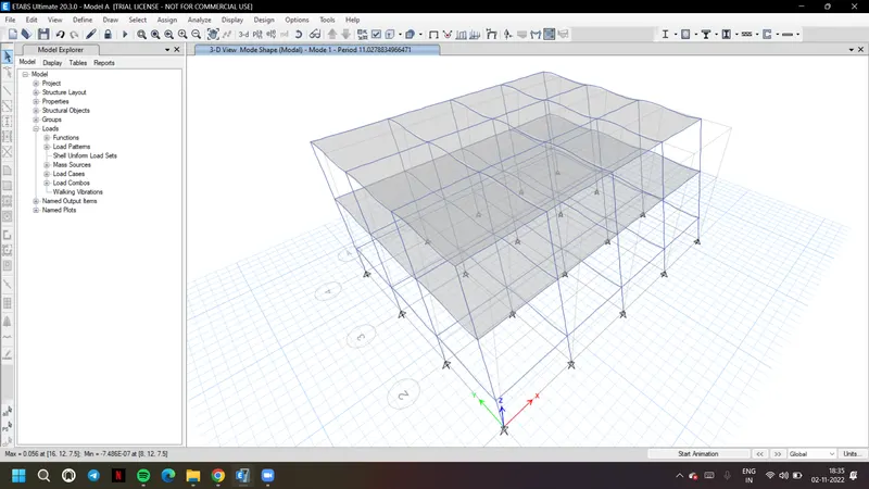
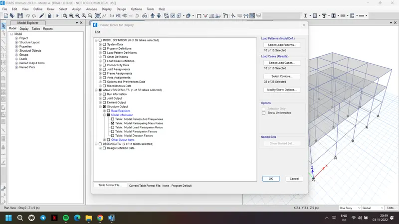
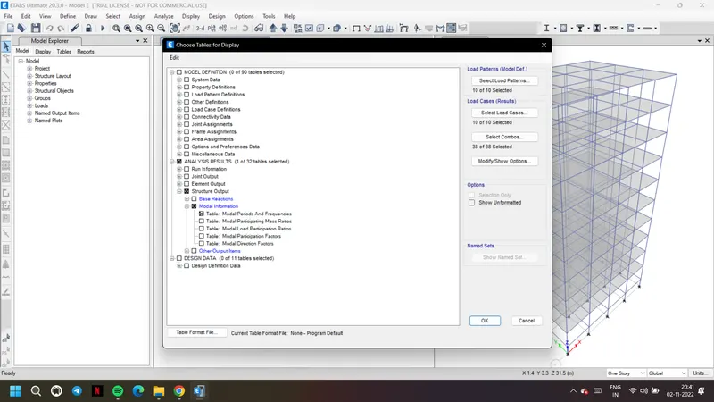
44. To check the analysis result, go to display and show tables
45. From that select the modal participating mass ratios from structure output
b) For Building B
1. Using save as option save the building A model as model B
2. Now the difference between A and B building is the number of stories
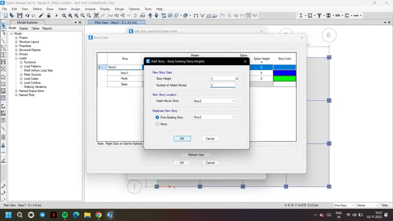
3. Go to edit, edit stories and modify the stories
4. Add the remaining stories and make them similar to storey 1
5. Now save it and check whether all including loads are applied for the newly added stories or not
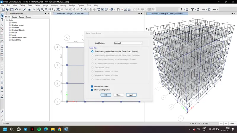
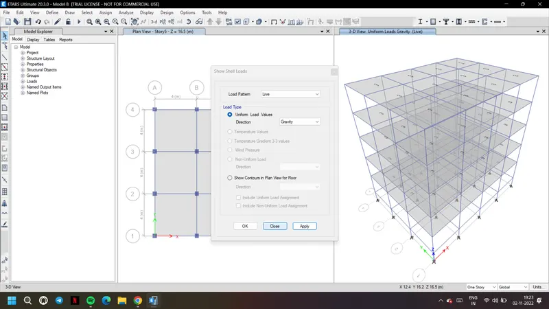
6. If everything is applied then select the slabs using select tab
7. Go to assign and again assign the diaphragm to it
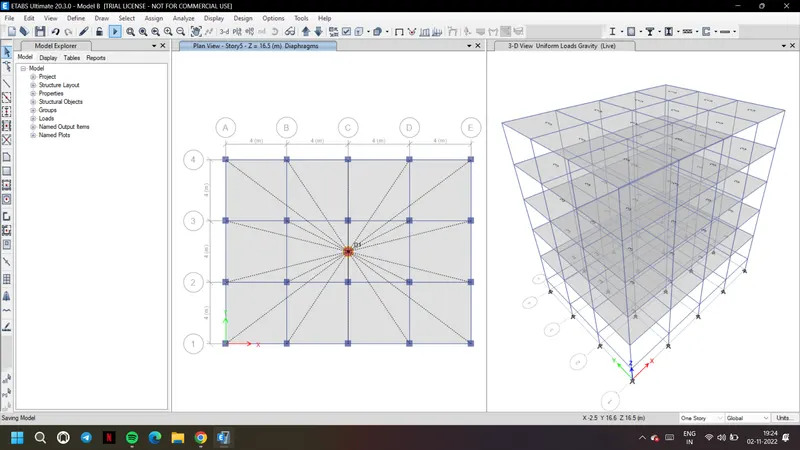
8. Save and run analysis
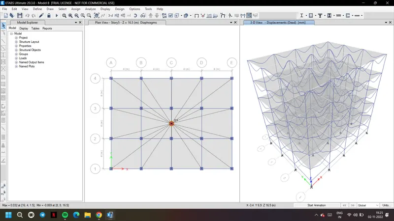
Now to check on the factors we also need to create another building B model with Nil flexural stiffness
1. For that using save as option save this model B as model B with Nil flexural stiffness
2. Go to define, section preperties and frame sections
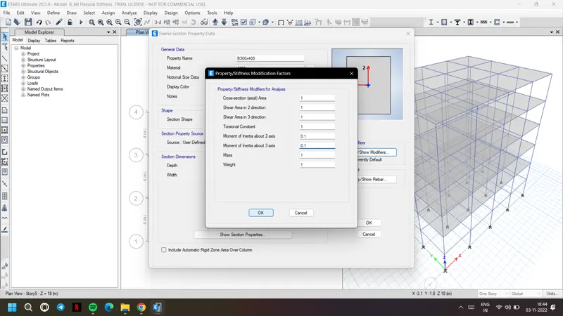
3. Now select the beam go to modify and then to property modifiers
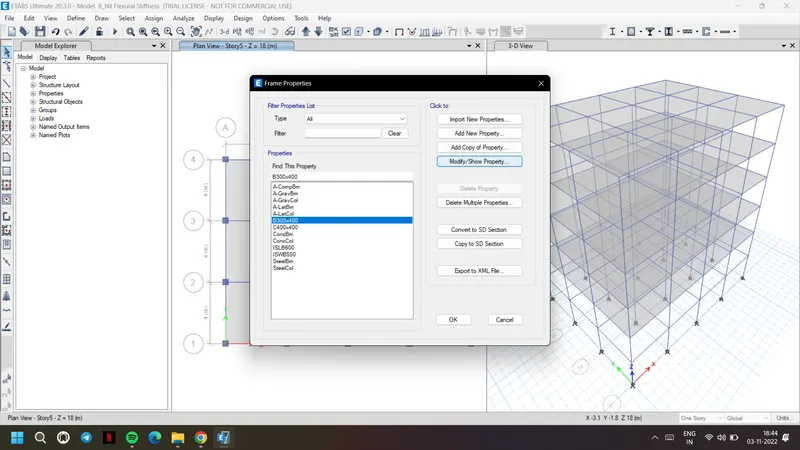
4. In that give, the moment of inertia of beam as 0.1 to get nil flexrural stiffness
5. Now save it and check whether all including loads are applied or not for all the stories
6. If everything is applied then select the slabs using select tab
7. Go to assign and again assign the diaphragm to it
8. Save and run analysis
Now to check on the factors we also need to create another building model B with fixed supports
1. For that using save as option save this model B as model B with fixed supports
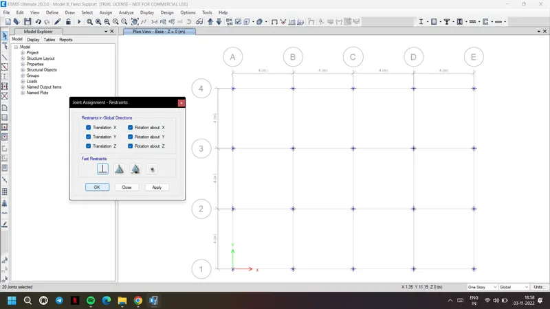
2. Open the base in plan view and select all the columns
3. Go to assign, joints and select the fixed support
4. Now save it and check whether all including loads are applied or not for all the stories
5. If everything is applied then select the slabs using select tab
6. Go to assign and again assign the diaphragm to it
7. Save and run analysis
c) For Building C
1. Using save as option save the building B model as model C
2. Now the difference between B and C building is the column size
3. Go to define, section prepoerties and frame sections and add new property
4. Add column of size 550x300mm similar to column 400x400 mm
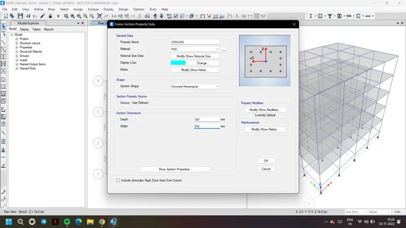
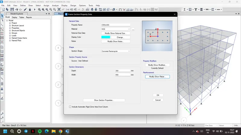
5. Now select all the columns using select tab and assign the c550x300mm
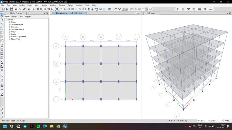
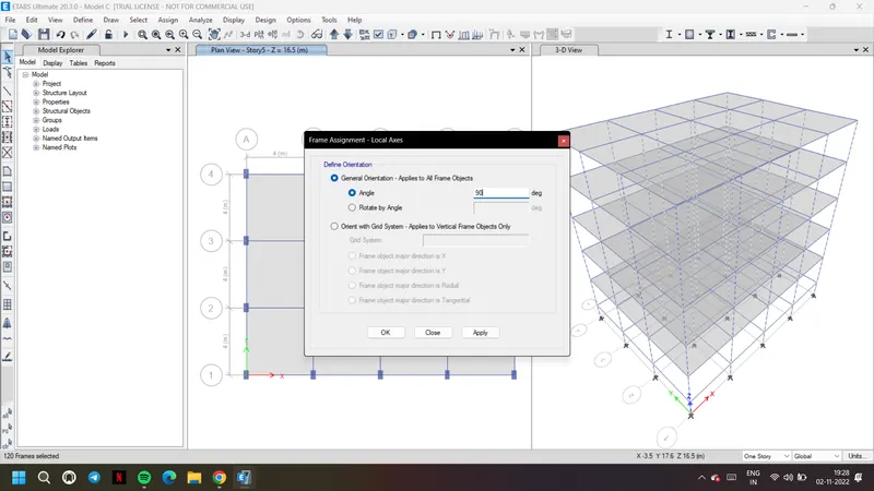
6, Now again selecting all columns, go to assign, frame and polar axes
7. Change the angle to 90 degrees to orient the columns
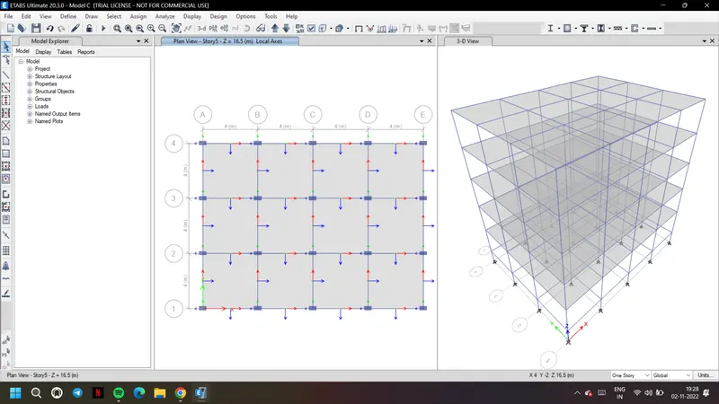
8. Now save it and check whether all including loads are applied or not for all the stories
9. If everything is applied then select the slabs using select tab
10. Go to assign and again assign the diaphragm to it
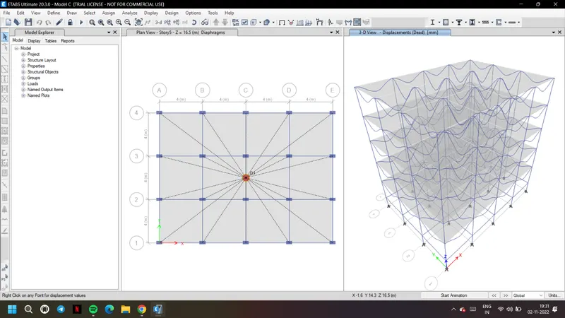
11. Save and run analysis
d) For Building D
1. Using save as option save the building C model as model D
2. Now the difference between C and D building is the column size or mainly orientation
3. Select all the columns using select tab
4. Got to assign, frame and polar axes
5. Change the angle to zero degrees to orient the columns to form 300x550 mm columns
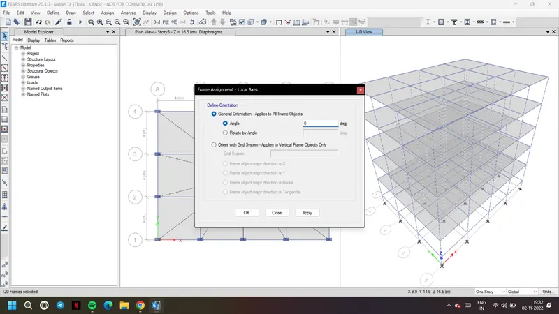
6. Now save it and check whether all including loads are applied or not for all the stories
7. If everything is applied then select the slabs using select tab
8. Go to assign and again assign the diaphragm to it
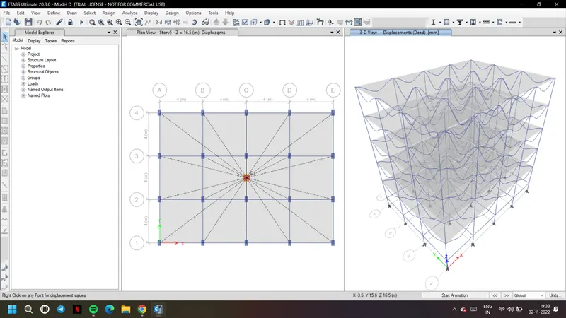
9. Save and run analysis
e) For Building E
1. Using save as option save the building D model as model E
2. Now the difference between D and E building is the number of stories and column sizes
3. Go to edit, edit stories and modify the stories
4. Add the reamining five stories and make them similar to storey 1
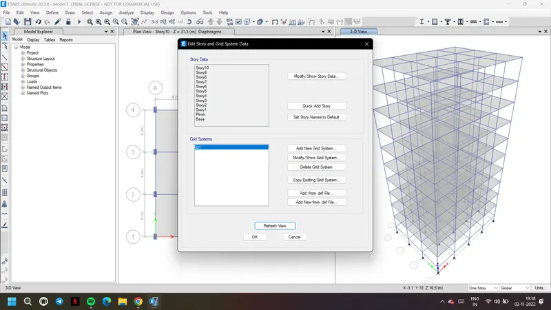
5. Now save it and check whether all including loads are applied for the newly added stories or not
6. Go to define, section prepoerties and frame sections and
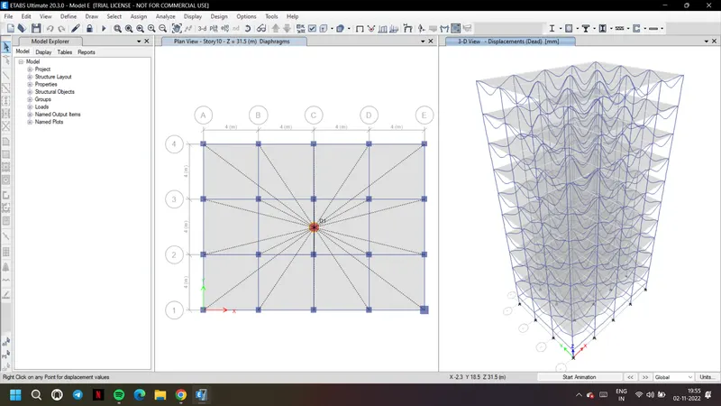
7. Modify the C550x300 mm to form the C600x600m
8. By saving it, the columns present would be modified to C600x600m
9. Now open 3d view, using display option off beams, floors and slabs to edit the columns
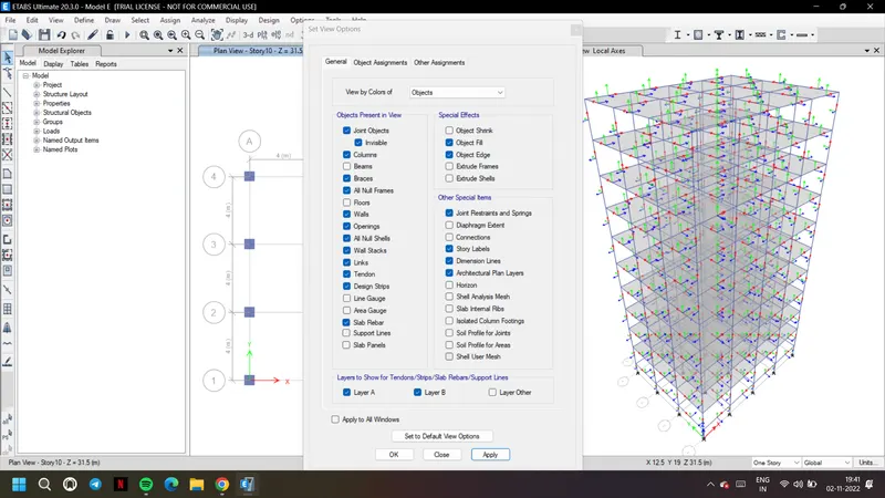
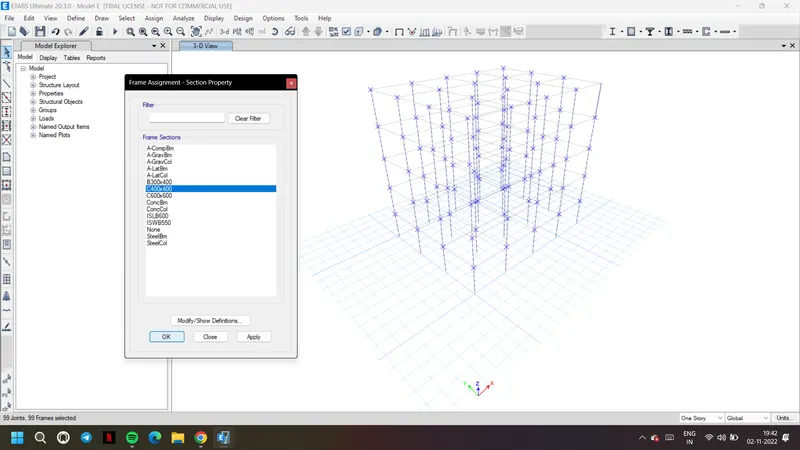
10. From view select, set building view limits and choose from storey 6 to 10.
11. Now select and using assign, assign the C400x400 to the top five floors
12. Now change view limits to view total building and display all beams and floors
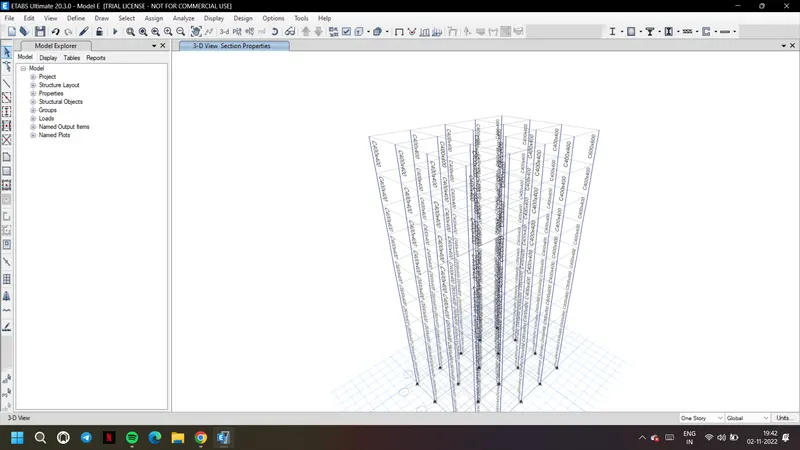
13. Now save it and check whether all including loads are applied or not for all the stories
14. If everything is applied then select the slabs using select tab
15. Go to assign and again assign the diaphragm to it
16. Save and run analysis
f) For Building F
1. Using save as option save the building E model as model F
2. Now the difference between E and F building is the column size in top five stories
3. 0pen 3d view, using display option off beams, floors and slabs to edit the columns
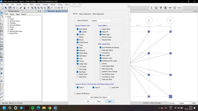
4. From view select, set building view limits and choose from storey 6 to 10.
5. Now select and using assign, assign the C600x600 to the top five floors
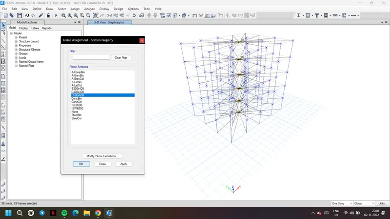
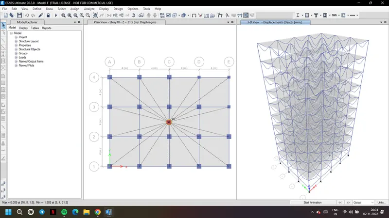
6. Now change view limits to view total building and display all beams and floors
7. Now save it and check whether all including loads are applied or not for all the stories
8. If everything is applied then select the slabs using select tab
9. Go to assign and again assign the diaphragm to it
10. Save and run analysis
g) For Building G
1. Using save as option save the building F model as model G
2. Now the difference between F and G building is the number of stories and column sizes
3. Go to edit, edit stories and modify the stories
4. Add the reamining fifteen stories to from 25 story building and make them similar to storey 1
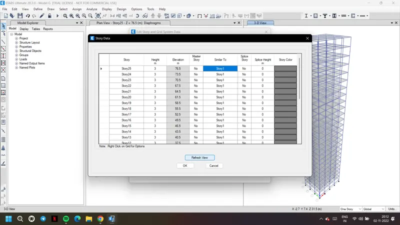
5. Now save it and check whether all including loads are applied for the newly added stories or not
6. Go to define, section prepoerties and frame sections and add new property
7. Add column of size 800x800mm similar to column 400x400 mm
8. Now select all the columns using select tab and assign the C800x800mm
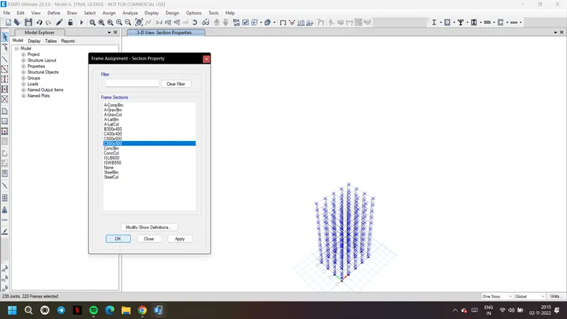
9. Now open 3d view, using display option off beams, floors and slabs to edit the columns
10. From view select, set building view limits and choose from storey 11 to 20.
11. Now select and using assign, assign the C600x600 to the middle ten floors
12. From view select, set building view limits and choose from storey 21 to 25.
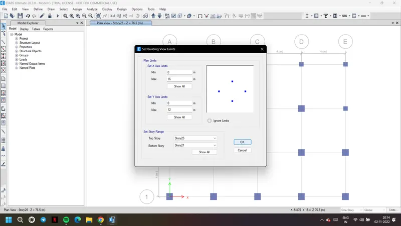
13. Now select and using assign, assign the C400x400 to the top five floors
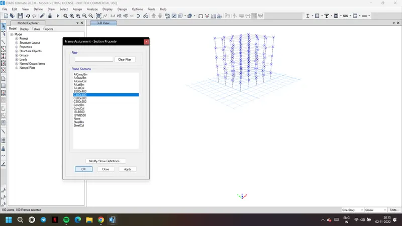
14. Now change view limits to view total building and display all beams and floors
15. Now save it and check whether all including loads are applied or not for all the stories
16. If everything is applied then select the slabs using select tab
17. Go to assign and again assign the diaphragm to it
18. Save and run analysis
h) For Building H
1. Using save as option save the building G model as model H
2. Now the difference between G and H building is the column size in top fifteen stories
3. Open 3d view, using display option off beams, floors and slabs to edit the columns
4. From view select, set building view limits and choose from storey 11 to 25.
5. Now select and using assign, assign the C800x800 to the top fifteen floors
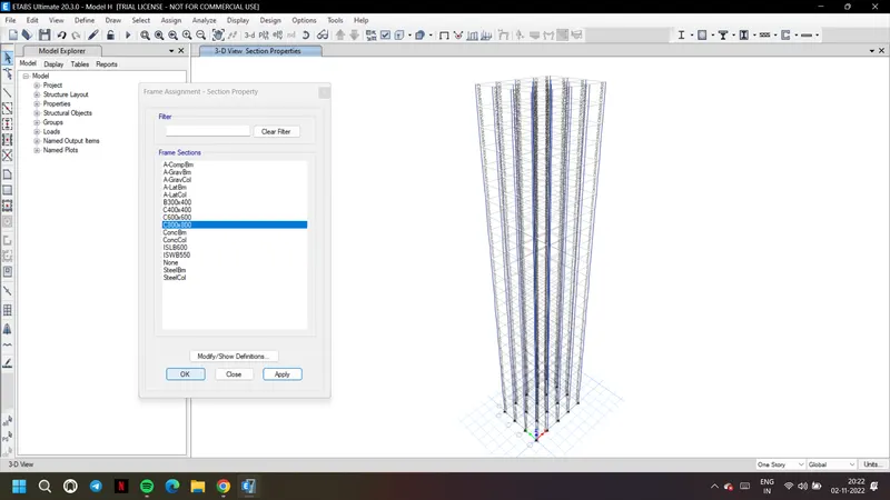
6. Now change view limits to view total building and display all beams and floors
7. Now save it and check whether all including loads are applied or not for all the stories
8. If everything is applied then select the slabs using select tab
9. Go to assign and again assign the diaphragm to it
10. Save and run analysis
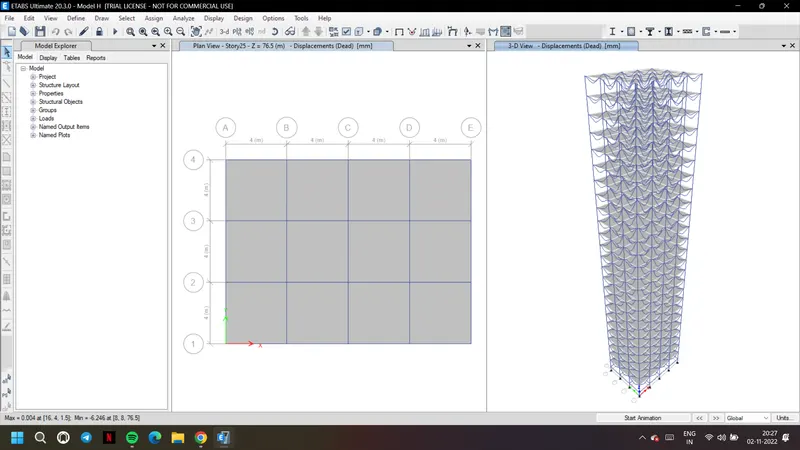
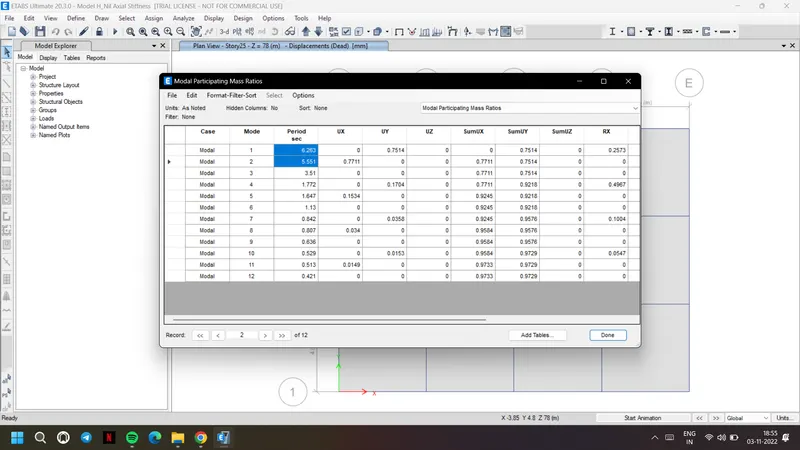
Now to check on the factors we also need to create another building H model with Nil axial stiffness
1. For that using save as option save this model H as model H with Nil axial stiffness
2. Go to define, section preperties and frame sections
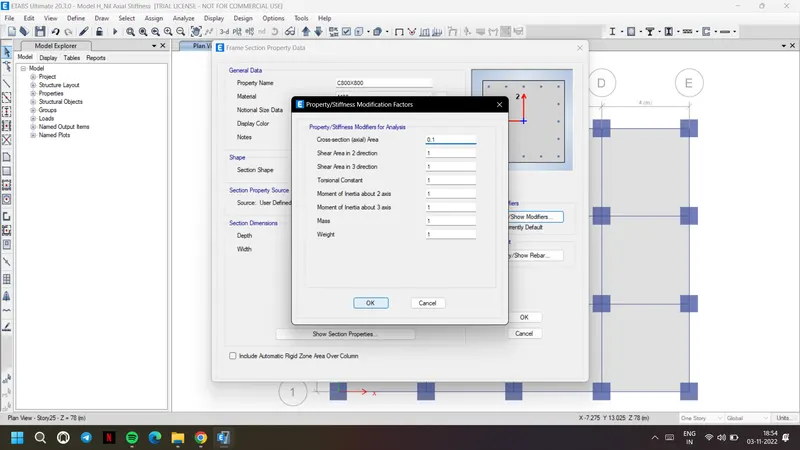
3. Now select the bcolumn go to modify and then to property modifiers
4. In that give, the cross sectional area of column as 0.1 to get nil axial stiffness
5. Now save it and check whether all including loads are applied or not for all the stories
6. If everything is applied then select the slabs using select tab
7. Go to assign and again assign the diaphragm to it
8. Save and run analysis
i) For Building J
1. Using save as option save the building H model as model J
2. Now the difference between H and J building is the mass applied on it
3. Select the all beams using select tab as shown
4. Now go to assign, frame loads and distributed
5. Change the live to 3.3 kN/m^2 as mentioned 10 percent increase in mass
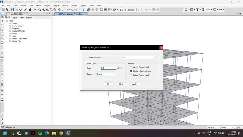
6. Now save it and check whether the load is changed to 3.3 for all floors instead of 3
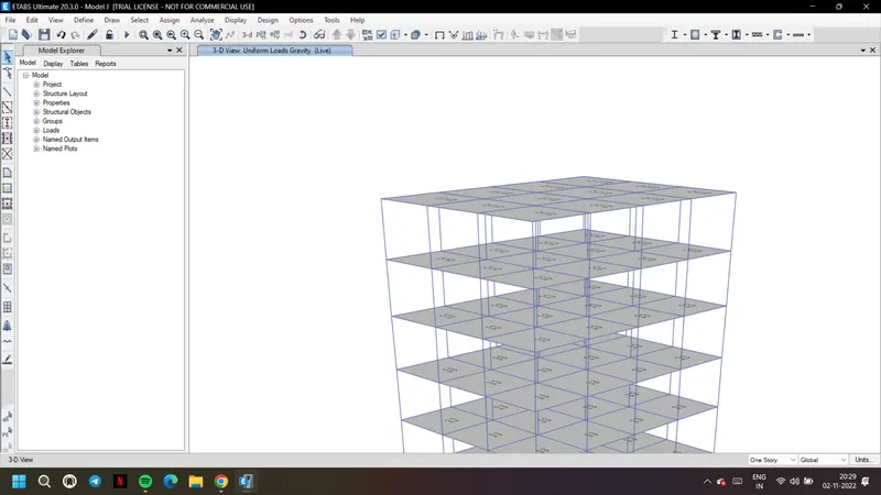
7. If everything is applied then select the slabs using select tab
8. Go to assign and again assign the diaphragm to it
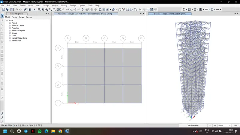
9. Save and run analysis
j) For Building K
1. Using save as option save the building J model as model K
2. Now the difference between J and K building is the mass applied on it
3. Select the all beams using select tab as shown
4. Now go to assign, frame loads and distributed
5. Change the live to 3.6 kN/m^2 as mentioned 20 percent increase in mass
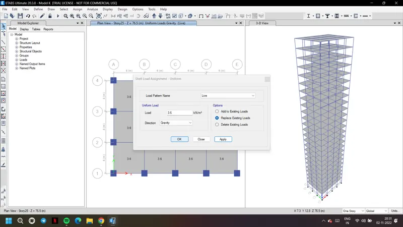
6. Now save it and check whether the load is changed to 3.6 for all floors instead of 3.3
7. If everything is applied then select the slabs using select tab
8. Go to assign and again assign the diaphragm to it
9. Save and run analysis
Results:
Ten different storey of buildings with given different conditions are modelled. Please find below the results after analysis
For Building A
For Building B
With Nil Flexural Stiffness
With Fixed supports
For Building C
For Building D
For Building E
For Building F
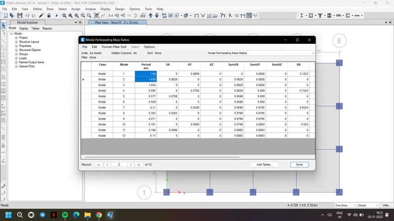
For Building G
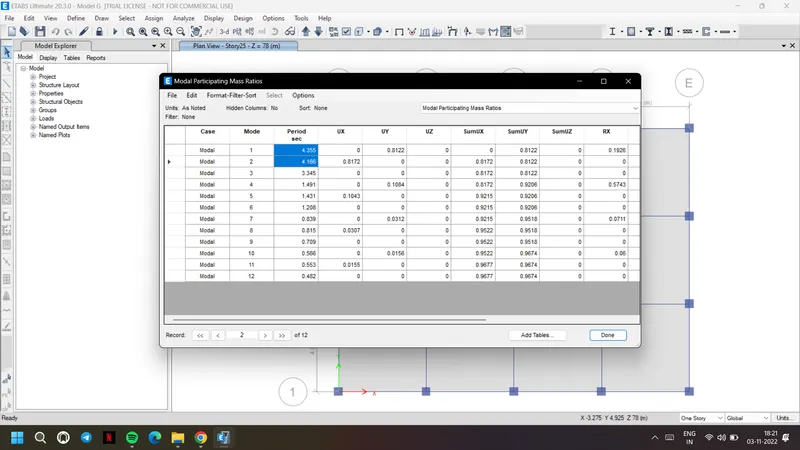
For Building H
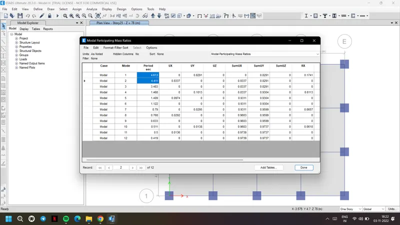
With Nil Axial Stiffness
For Building J
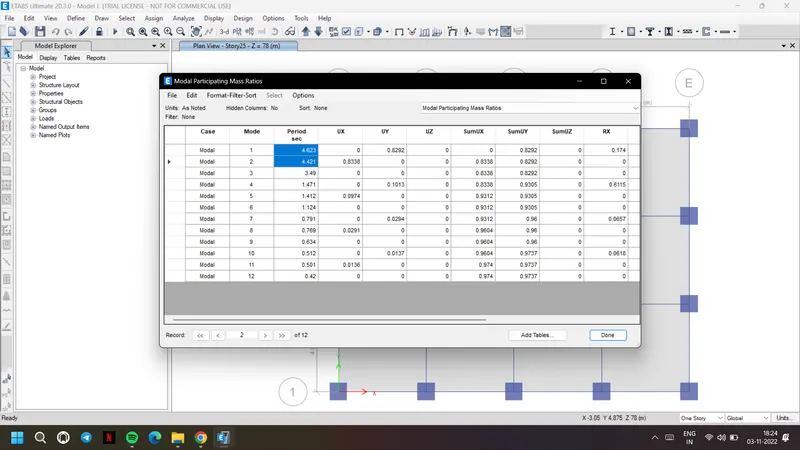
For Building K
Review on the given characteristics is mentioned below:
Factors influencing the dynamic characteristics of a building
1. Buildings oscillate during earthquake shaking. The oscillation causes inertia force to be induced in the building.
2. The intensity and duration of oscillation, and the amount of inertia force induced in a building depend on features of buildings, called their dynamic characteristics, in addition to the characteristics of the earthquake shaking itself.
3. The important dynamic characteristics of buildings are modes of oscillation and damping. A mode of oscillation of a building is defined by associated Natural Period and Deformed Shape in which it oscillates.
4. Every building has a number of natural frequencies, at which it offers minimum resistance to shaking induced by external effects and internal effects.
5. Each of these natural frequencies and the associated deformation shape of a building constitute a Natural Mode of Oscillation.
6. The mode of oscillation with the smallest natural frequency is called the Fundamental Mode; the associated natural period T1 is called the Fundamental Natural Period.
7. Regular buildings held at their base from translation in the three directions, have two fundamental translational natural periods, Tx1 and Ty1, associated with its horizontal translational oscillation along X and Y directions, respectively, and one fundamental rotational natural period Tθ1 associated with its rotation about an axis parallel to Z axis.
Factors influencing the Natural Period of a building
a) Effect of stiffness on T: Compare fundamental natural periods of buildings E & F as well as G & H. Why is there a marginal or significant difference in the fundamental natural periods?
Results:
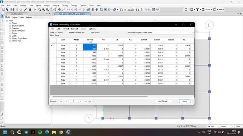
1. The fundamental natural periods of building E is Tx1 = 1.863 and Ty1=1.923
The fundamental natural periods of building F is Tx1 = 1.878 and Ty1=1.94
2. The fundamental natural periods of building G is Tx1 = 4.166 and Ty1=4.355
The fundamental natural periods of building H is Tx1 = 4.411 and Ty1=4.613
Observations:
1. There is no much difference between natural period of building E and F as the column size is varying only in top five stories
2. The natural period of building H having uniform column size is more than the building G with varying column size.
3. Here the building G with varying column size is more stable than the building H with same column size.
4. Providing larger columns at the base and then reducing the size on top floors results in reduction of stiffness and mass and helps in reduction of the natural period T for tall buildings
5. Stiffness of the building increases with increase in column size thus resulting in greater natural period
6. It can also be noted that, when the percentage increase in stiffness as a result of an increase in column size is larger than the percentage increase in mass, then the natural period reduces.
b) Effect of mass on T: Compare fundamental natural periods of buildings H, J and K. Have the buildings become more flexible or stiff due to change in mass?
Results:
The fundamental natural periods of building H is Tx1 = 4.411 and Ty1=4.613
The fundamental natural periods of building J is Tx1 = 4.421 and Ty1=4.623
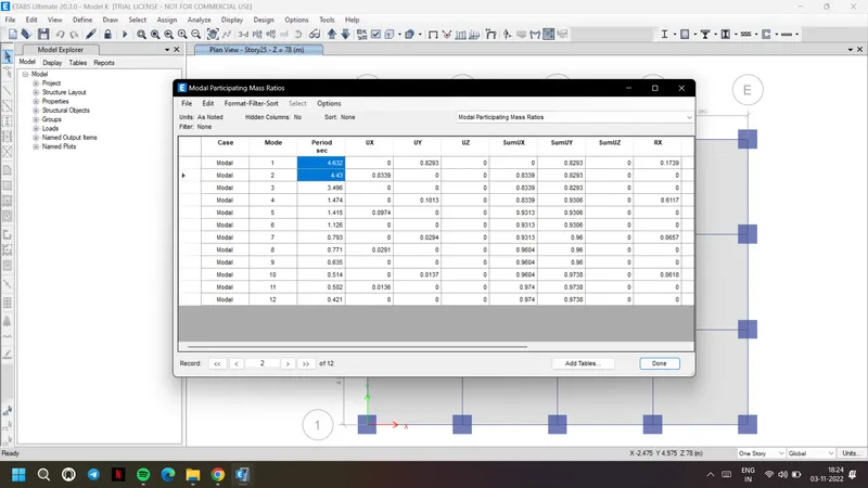
The fundamental natural periods of building K is Tx1 = 4.43 and Ty1=4.632
Observations:
1. The increase in time period is not that significant it may be because only a little amount of mass uiformly increased for J and K buildings
2. The time period increases with increase in the mass of the building
C) Effect of Building Height on T: How does the fundamental natural periods of Buildings A, B, F and H change with change in building height?
Results:
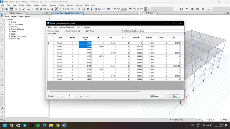
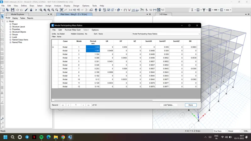
The fundamental natural periods of building A is Tx1=0.744 and Ty1=0.758
The fundamental natural periods of building B is Tx1=1.303 and Ty1=1.33
The fundamental natural periods of building F is Tx1 = 1.878 and Ty1=1.94
The fundamental natural periods of building H is Tx1 = 4.411 and Ty1=4.613
Observations:
1. We can observe that the time period of buildings has increased with increase in the height of the building
2. The time period increases with increase in height of the building
D) Effect of Column Orientation on T: How does the fundamental natural periods of Buildings B, C and D change with change in column orientation?
Results:
The fundamental natural periods of building B is Tx1=1.303 and Ty1=1.33
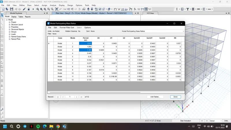
The fundamental natural periods of building C is Tx1 = 1.157 and Ty1=1.517
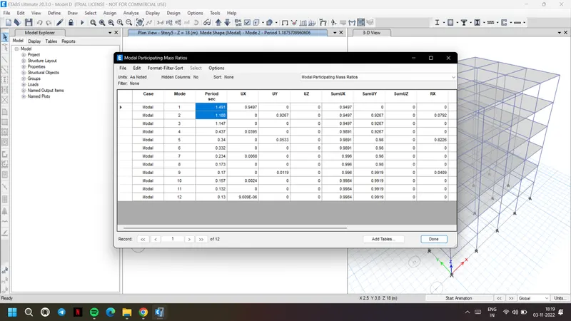
The fundamental natural periods of building D is Tx1= 1.491 and Ty1=1.188
Observations:
1. The natural periods of building B in x and y direction is almost same as column is a symmetric column
2. In x-direction, building c having 550 mm, B has 400 mm and D has 300 mm dimensions and there time periods are increasing. Similarly for y-direction, time periods are increasing with decrease in column size.
3. For building C, in X direction as dimension is more 550mm the time period is less and y direction time period is more as dimension is 300mm. For D building it is 300x550 mm, in x direction time period is more than y direction
4. As per the column orientation of a building, natural period of buildings along the longer direction of column cross-section is smaller than that along the shorter direction.
Factors influencing the Mode shape of oscillations
a) Effect of Flexural Stiffness of Structural Elements on mode shapes: Compare fundamental mode shape of Building B in two situations when flexural stiffness of beams relative to that of adjoining columns is very small versus when it is large.
Results:
The fundamental natural periods of building B when full flexural stiffness of beam is considered: Tx1=1.303 and Ty1=1.33
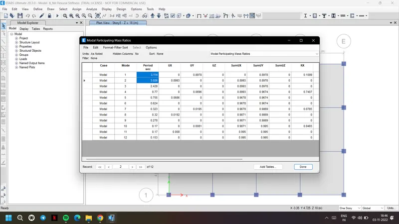
The fundamental natural periods of building B when flexural stiffness of beam is considered to be nil: Tx1=3.026 and Ty1=3.114
Observations:
If flexural stiffness of beam is taken as very small then the time period of the building is more than doublt than the beams at full flexural stiffness
If the flexural stiffness of beams decreases, the overall flexural strength of the beam is also going to reduce, and consequently, the fundamental natural period will increase.
b) Effect of Axial Stiffness of Vertical Members on mode shapes: Compare fundamental mode shape of Building H in two situations when axial cross-sectional area of columns is very small versus when it is large.
Results:
The fundamental natural periods of building H when full axial stiffness of column is considered: Tx1 = 4.411 and Ty1=4.613
The fundamental natural periods of building H when axial stiffness of column is considered to be nil: Tx1=5.551 and Ty1=6.263
Observations:
1. If axial stiffness of column is taken as very small then the time period of the building is more than the column at full axial stiffness
2. As the axial stiffness of columns decreases, the fundamental natural period of the building increases regardless of its structural geometry.
c) Effect of Degree of Fixity at column bases on mode shape: Compare fundamental mode shape of Building B in two situations when base of columns is pinned versus when it is fixed.
Results:
1. The fundamental natural periods of building B when full flexural stiffness of beam is considered: Tx1=1.303 and Ty1=1.33
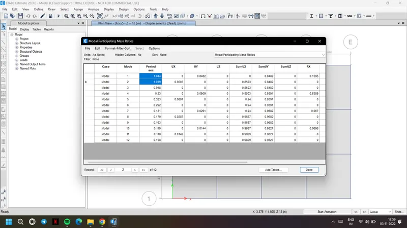
2. The fundamental natural periods of building B when flexural stiffness of beam is considered to be nil: Tx1=1.019 and Ty1=1.044
Observations:
1. Time period of building B is decreased when the support condition is changed from pinned to fixed
2. It is evident that pinned support offers fewer restraints compared to the fixed one which leads to more movement and thus increased natural period.
3. As a result, it can be concluded that the fixed support will give you better control over the fundamental natural period of buildings.