Project 1_Comparative study of different storey buildings for Seismic forces
Aim: To create the influencing of Dynamic charecteristics, Natural period and Mode shapes of a building.
Introduction: To create the influencing of Dynamic charecteristics, Natural period and Mode shapes of a building.
Procedure:
Model-A
- Open the Etabs software and click on the New Model.
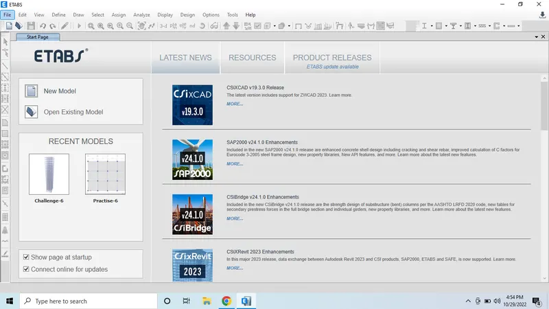
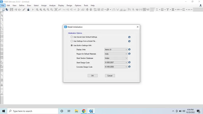
- Create the settings as per the units and codes in the drawing.
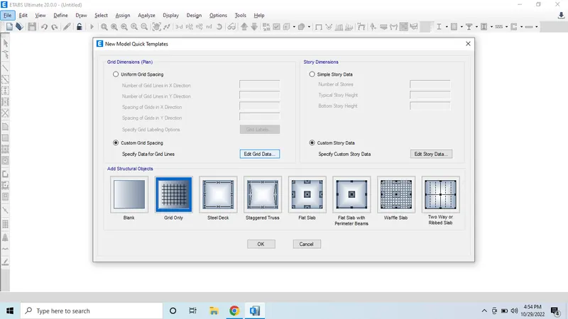
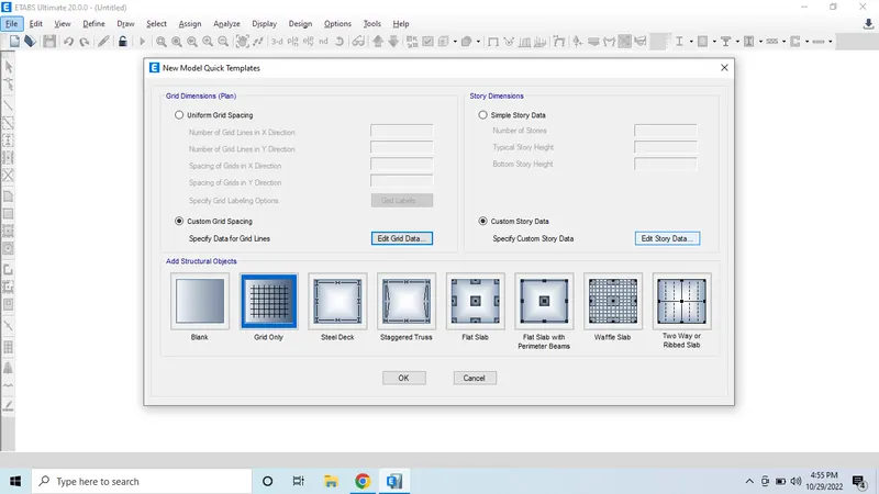
- Select create grid spacing and create story data to create grids and stories as per the building floors.
- There are 5 stories in the grdi data and add one grid at a distance of 4m for each grid.
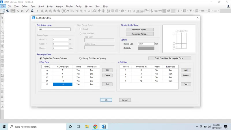
- Now after creating grids click ok.
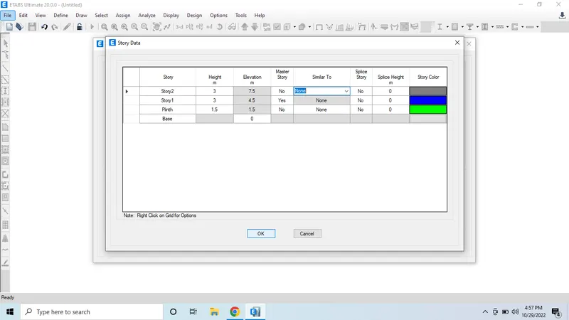
- For story in the first model there are only 2 stories.
- So we need to delete one story and mark the ssimilar to option for story 1.
- Then click ok.
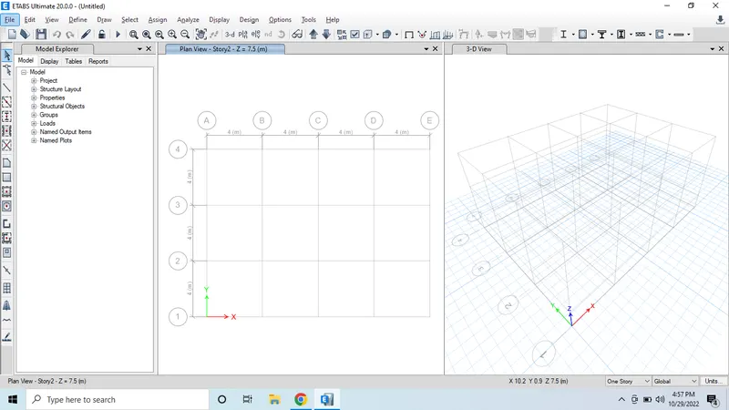
- Now we can see the plan and 3d model view.
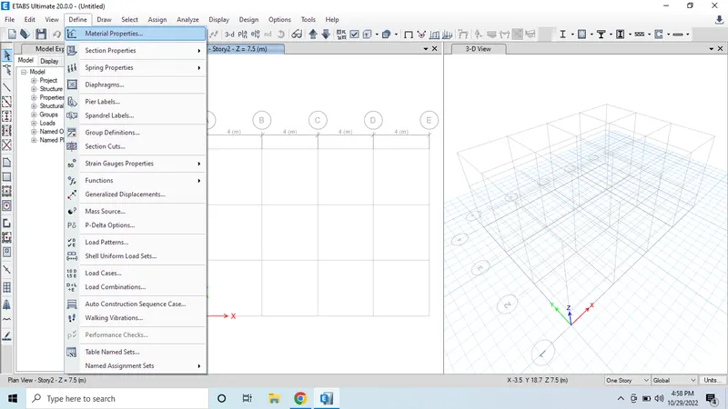
- Go to define tab and select material properties.
- Click on add new model option.
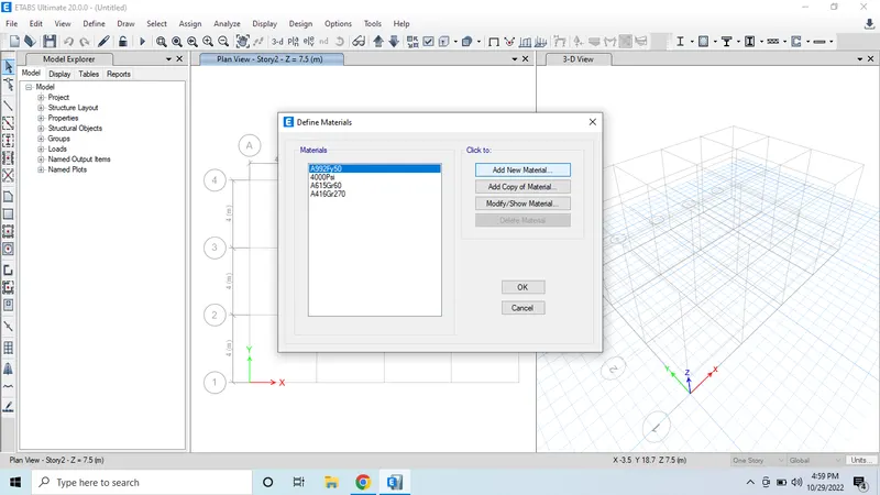
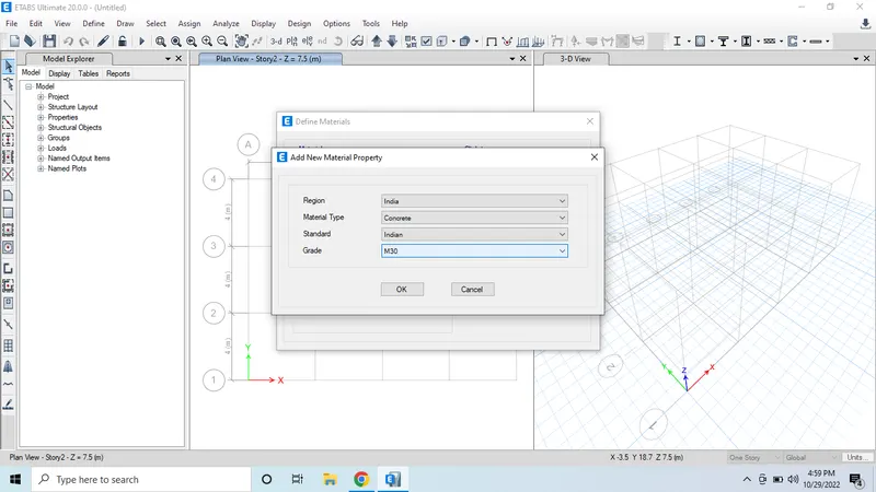
- Create M30 material for concrete.
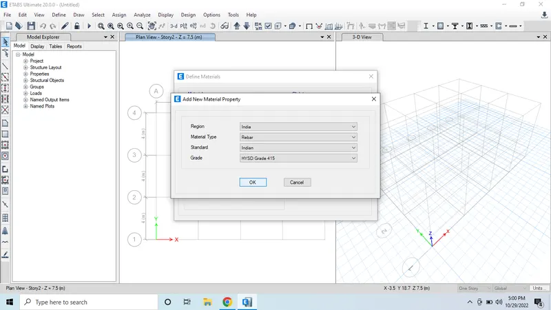
- In the same way create material for steel also.
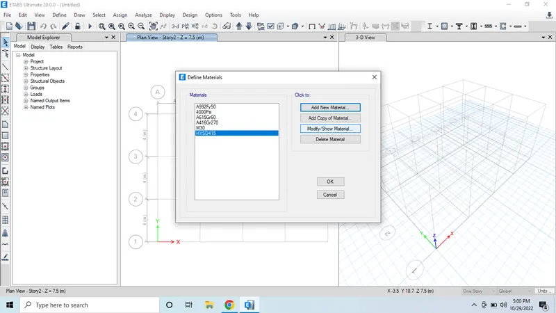
- Now we can see the materials which we added.
- Now go to define tab and click on the frame section for creating beams.
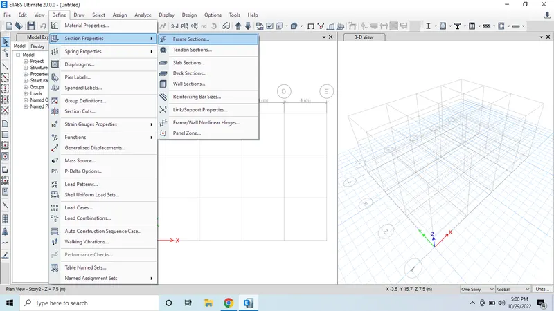
- Click on add new property.
-
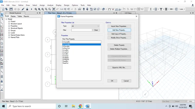
- Create beam size as in the given question.
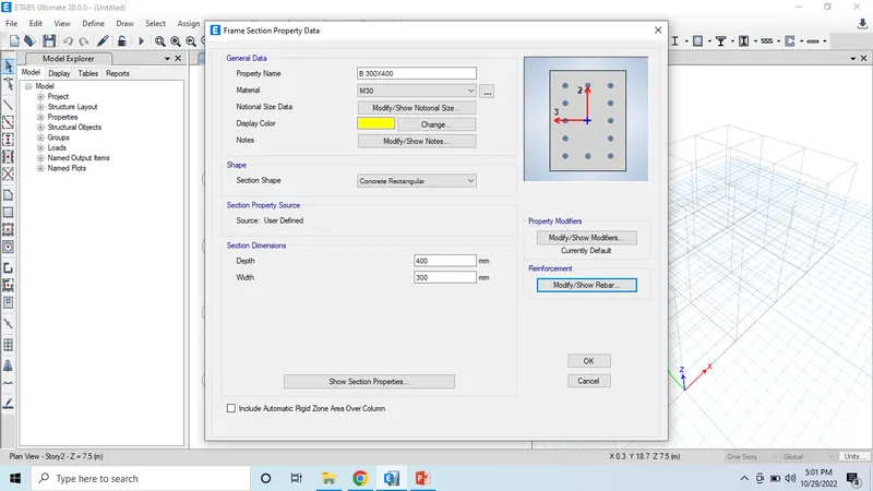
- Select beam option and give the bar options.
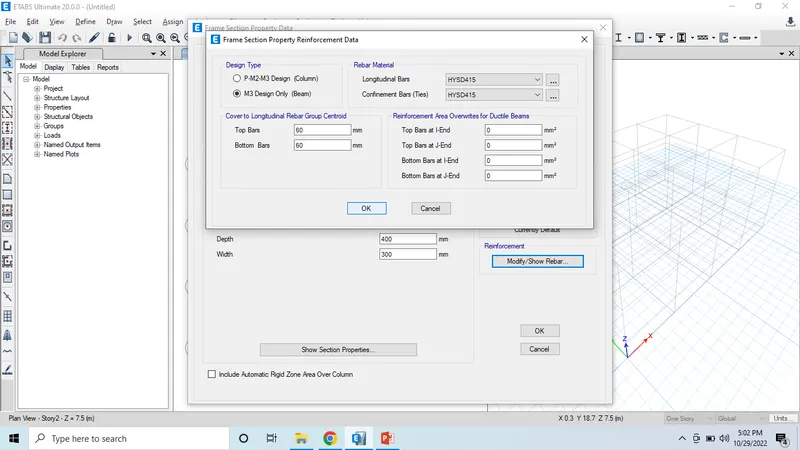
- Now we can see the beam size which we added.
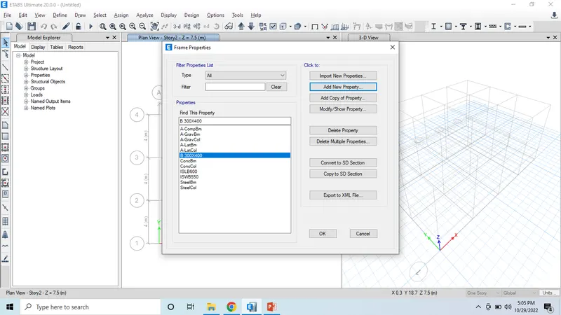
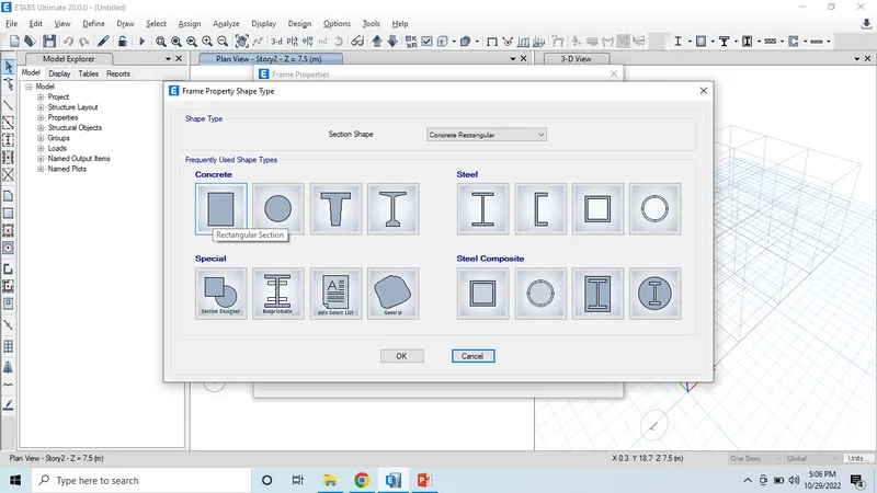
- Select concrete beam structure option.
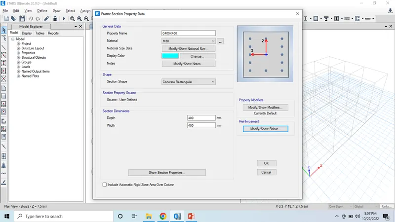
- Create column size as in the given question.
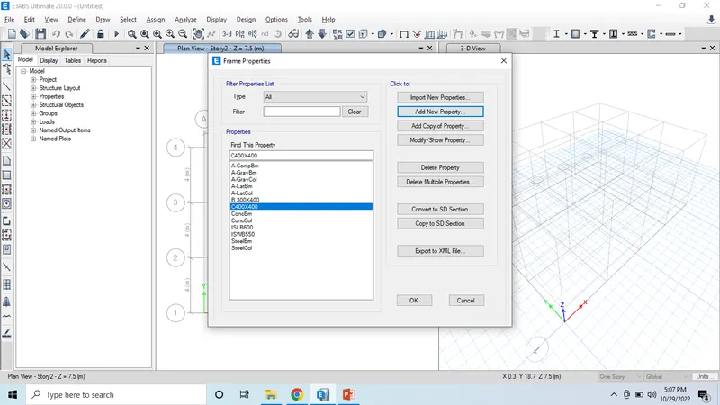
- After creating column click on ok.
- Now select section properties and select slab section.
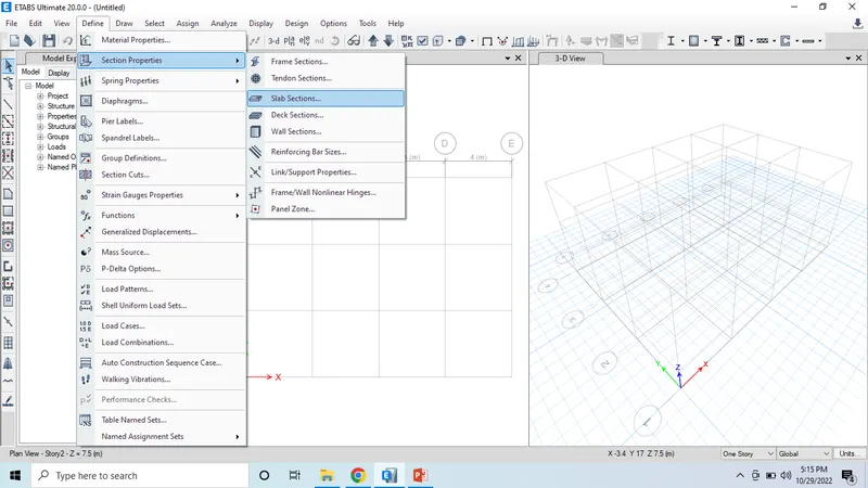
- Now mention slab dimensions and click ok.
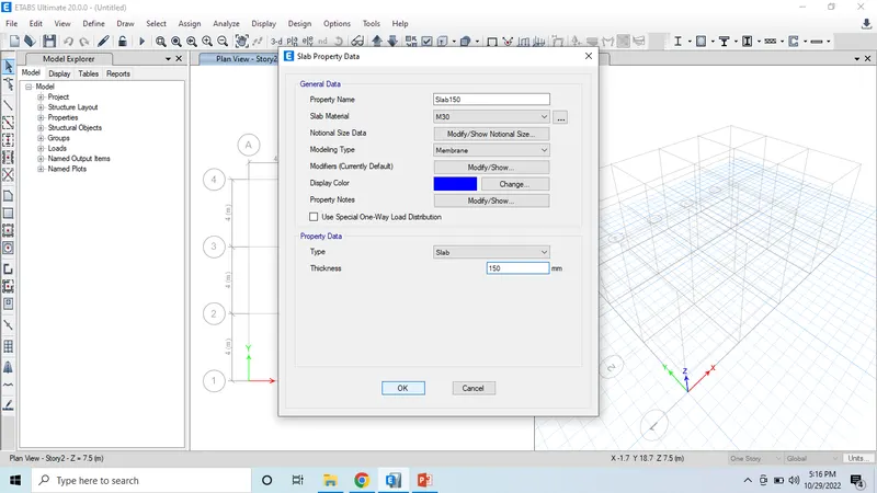
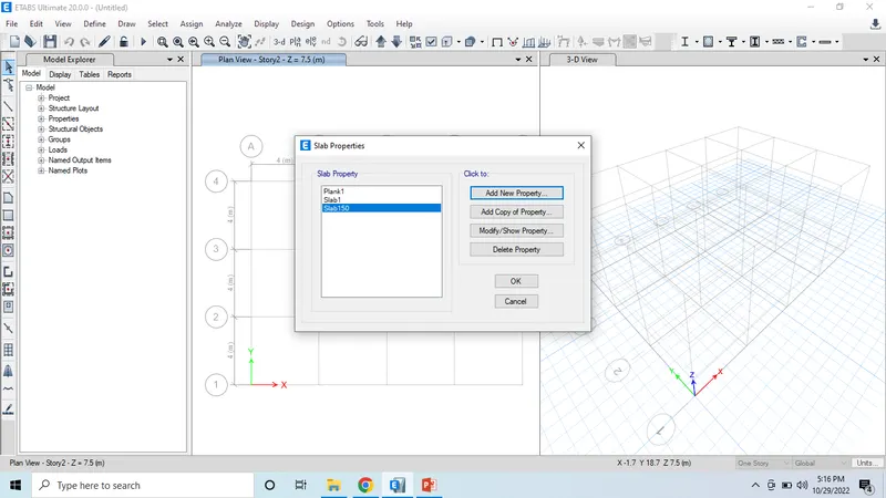
- Now we can see the slab material and click ok.
- Now we have to apply loads and select load frames.
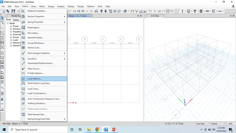
- Click on add new load option and add loads for lateral loads and displacements.
- Then click ok.
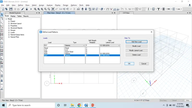
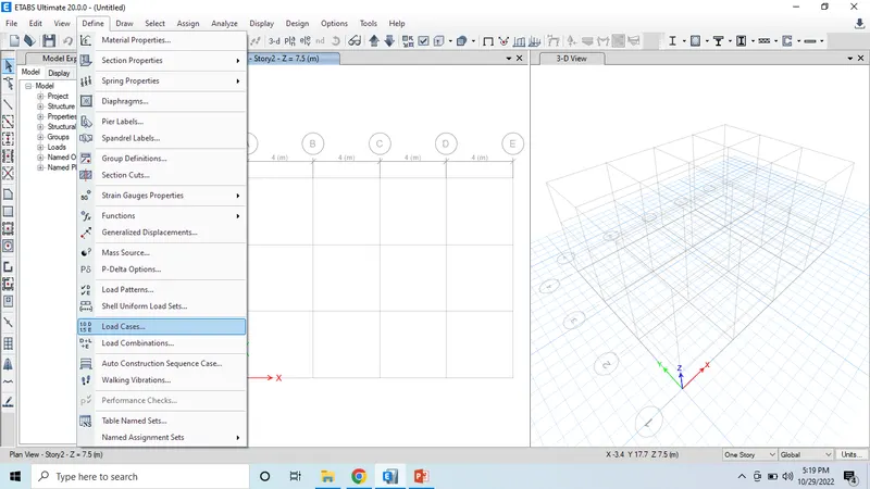
- Go to define tab and select load cases.
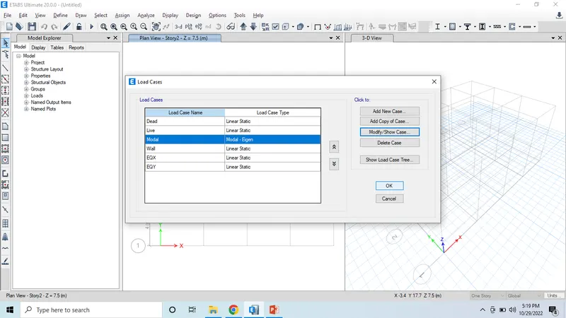
- Now click on mmodal case and click ok.
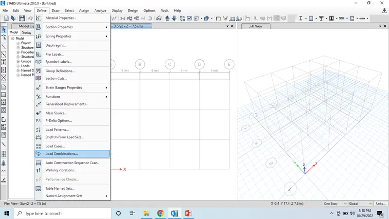
- Then go too define option and select load combinations.
- Select add default change option.
- Then click ok.
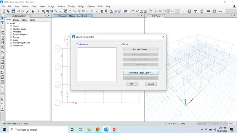
- Selct concrete frame design option.
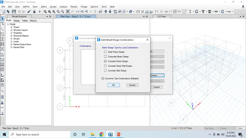
- Click ok.
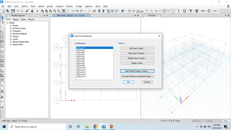
- Now we can see the plan and 3d plan with loads.
- Select quick column option.
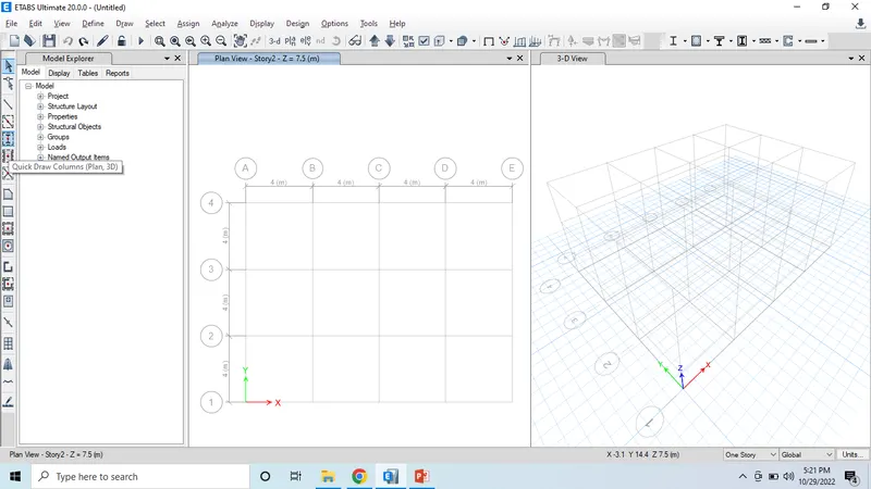
- Place the columns on the grids.
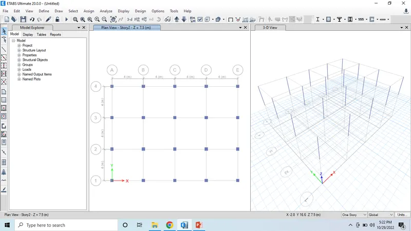
- Now we can see all the columns placed on the grids.
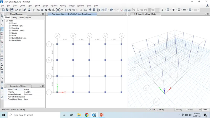
- Here we can see all the columns are placed on the grids.
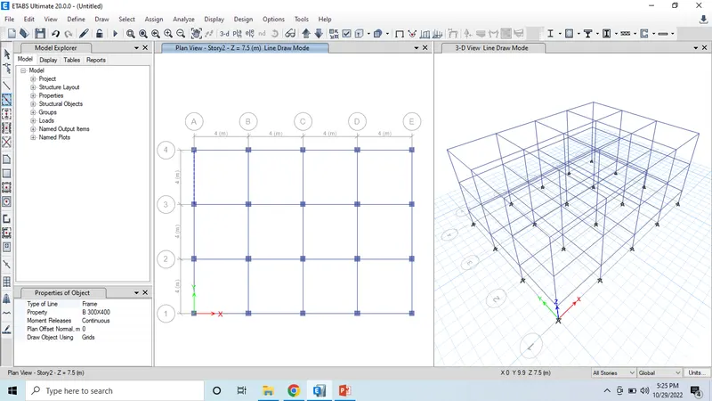
- Now select for quick draw frames for beams placing.
- Place all the beams on the grids.
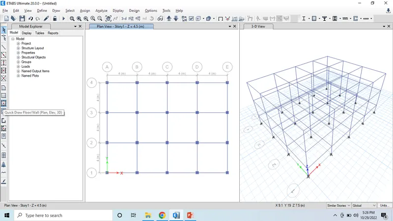
- Now select slabs and place all the slabs.
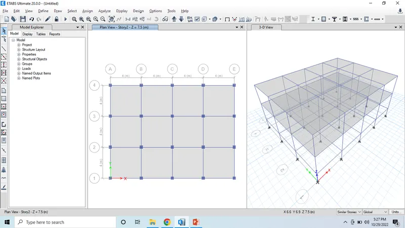
- Now we have to select all the slabs.
- Go to select option and click on frames option.
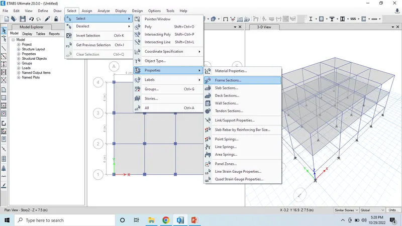
- Now select beams with size which we have created.
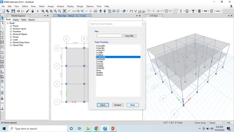
- We have to apply loads to the beams.
- Go to assign option and select distributed loads.
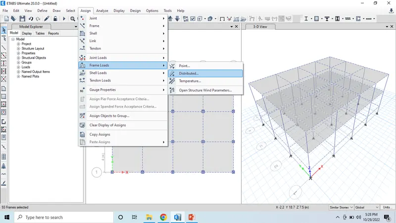
- Give the live load as 10kn/m as in the given question.
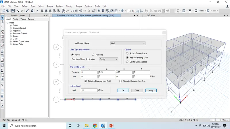
- Now we can see the loads applied to beams.
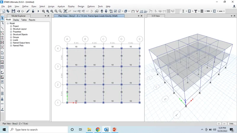
- Again go to select option and select slab sections.
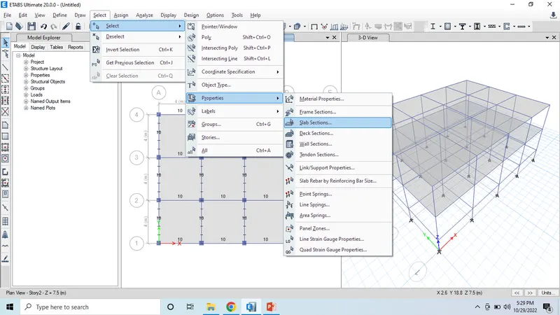
- Select slab length option.
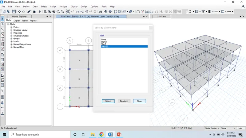
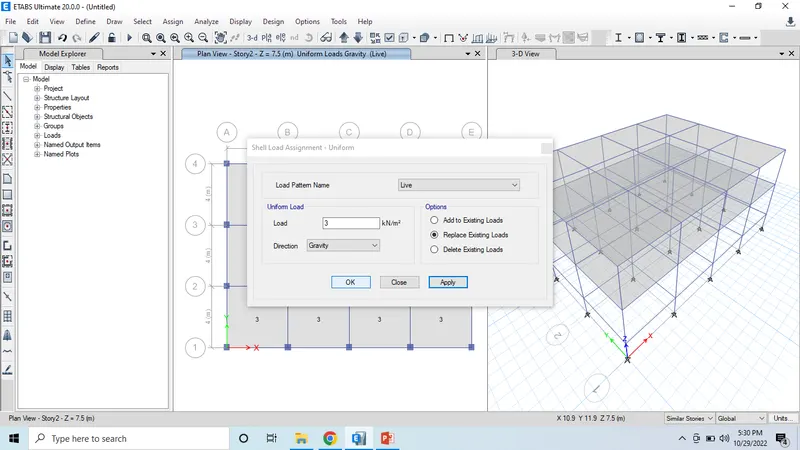
- Then assign the loads for slabs as uniform distributed loads.
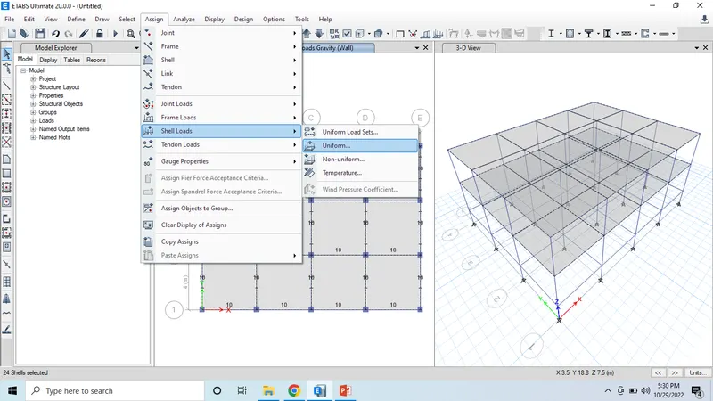
- assign the load as 3kn/m as per the question.
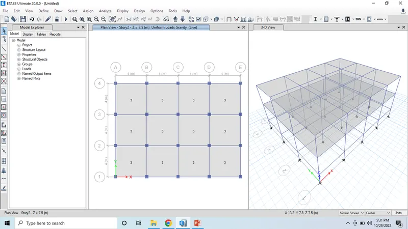
- Now we can see the load applied to the slab.
- Go to the define option and select main source option.
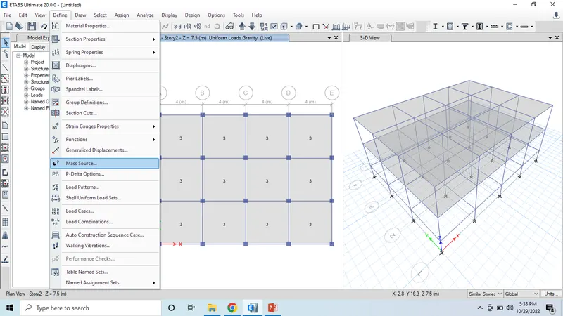
- Now click on the add mass source option.
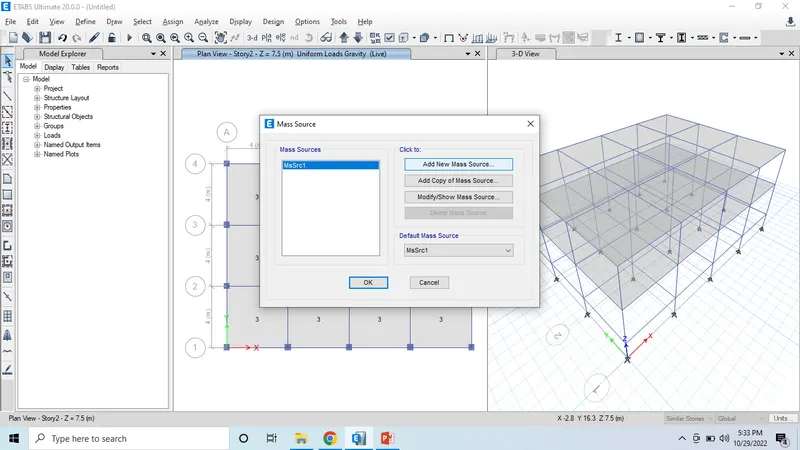
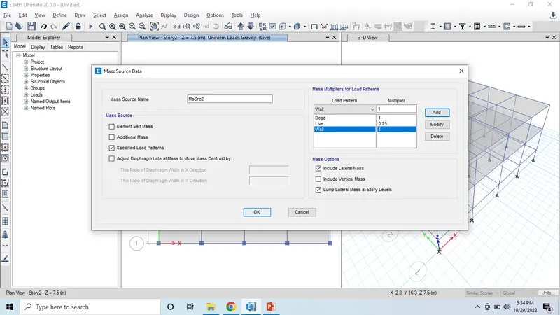
- Add the loads as dead, live and wall loads.
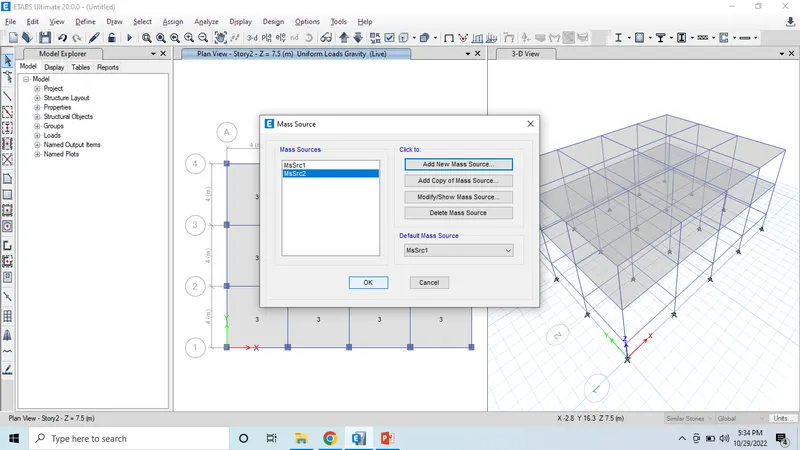
- We can see the new mass source select the mass source and click ok.
- Select all the slabs from select option.
- Go to assign option and selct shell and diaphragam option.
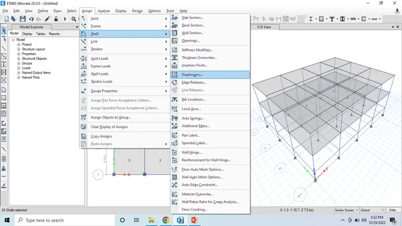
- Select d1 and click on ok.
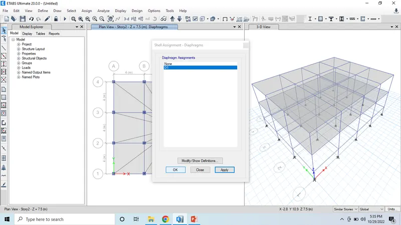
- Now we can see the diaphragam applied on the slabs.
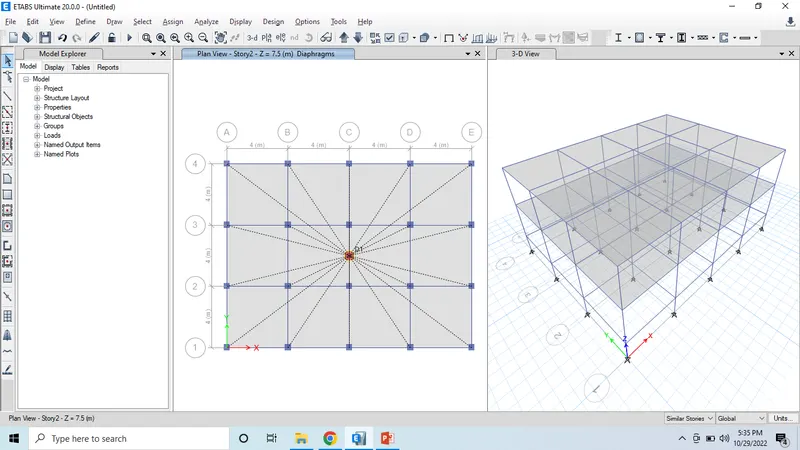
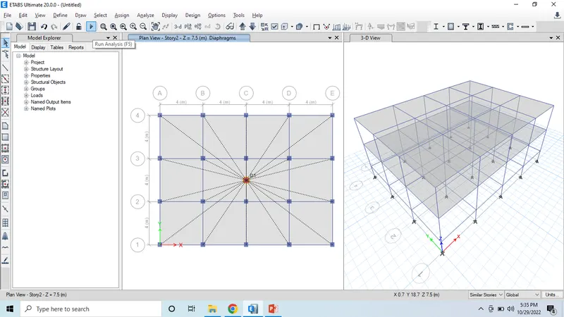
- click on run analysis option.
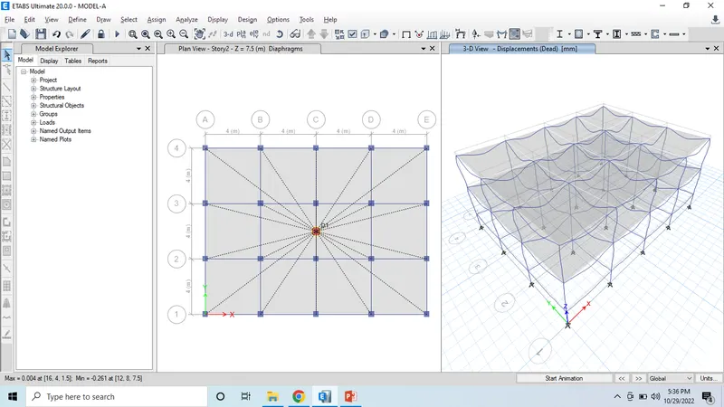
- Finallly we can see the diaphragam in the 3d view.
MODEL-B
- Click on the file option and save as the file to another name for model B.
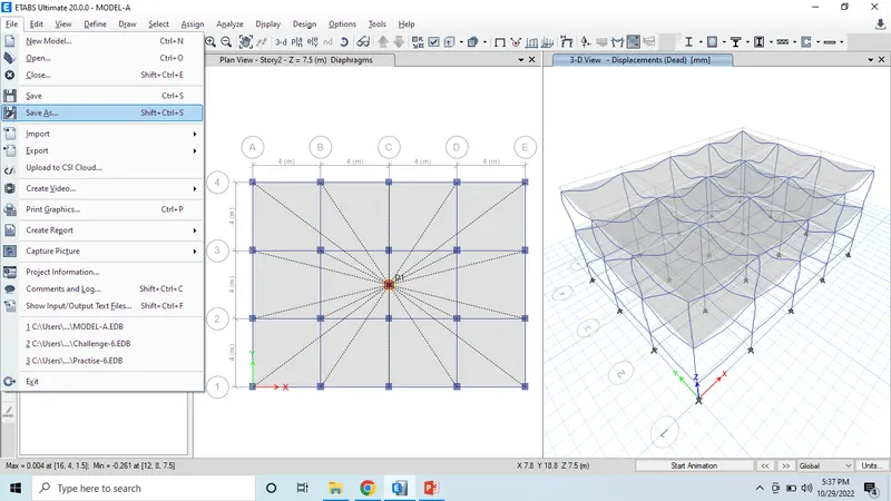
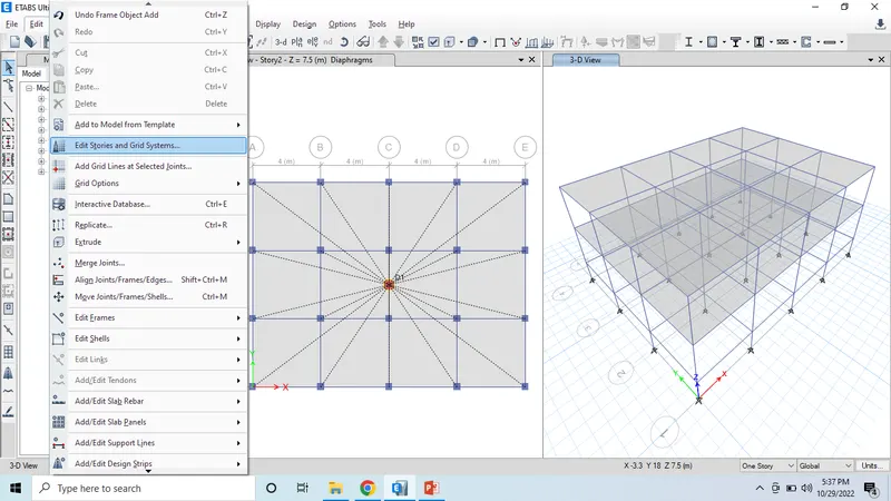
- To add the stories click on the edit stories option.
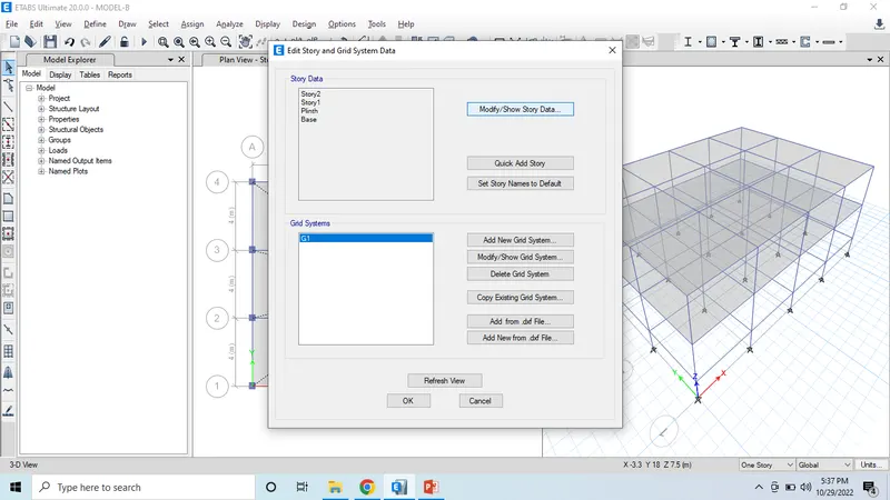
- Select modify story data option.
- Add the stories upto story 5.
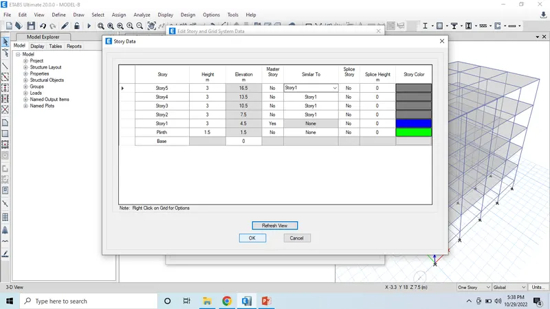
- Now click on refresh view and click on ok.
- Check the loads whether they are aplied to the added stories.
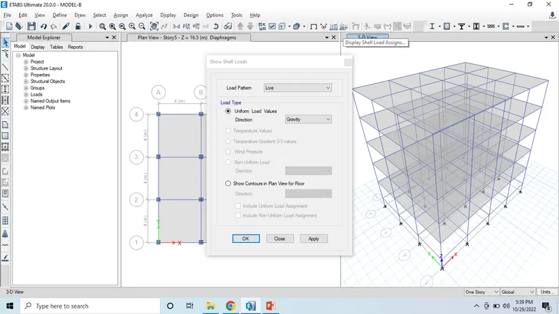
- Load is applied to all the stories.
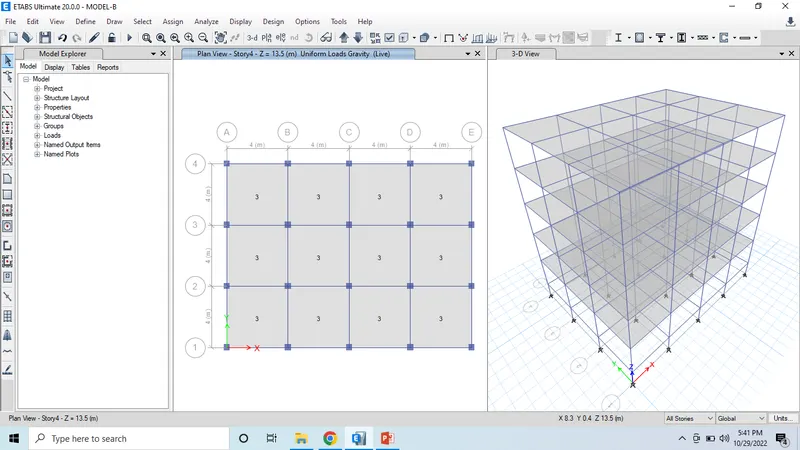
- Now in the same way check the wall loads.
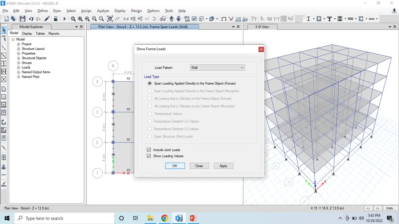
- Now we can see wall loads are also applied to all the stories.
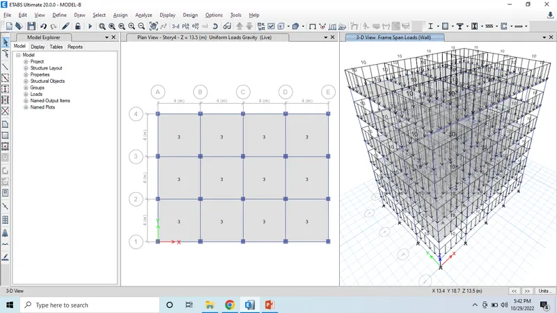
- Apply digphragam to the slabs.
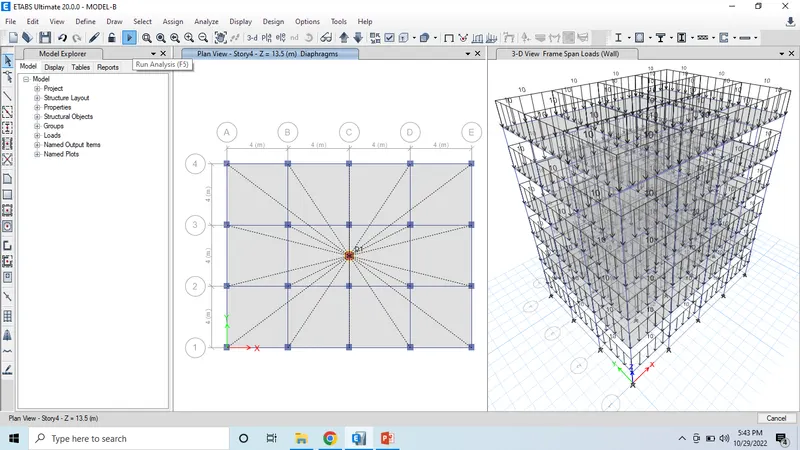
- Do the run analysis option.
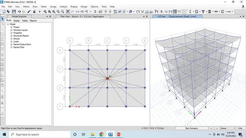
MODEL-C
- Do save as the file as model-C
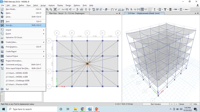
- Go to the define tab and select frame section option.
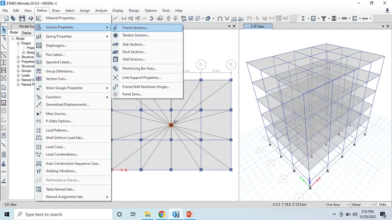
- Seelct the column option.
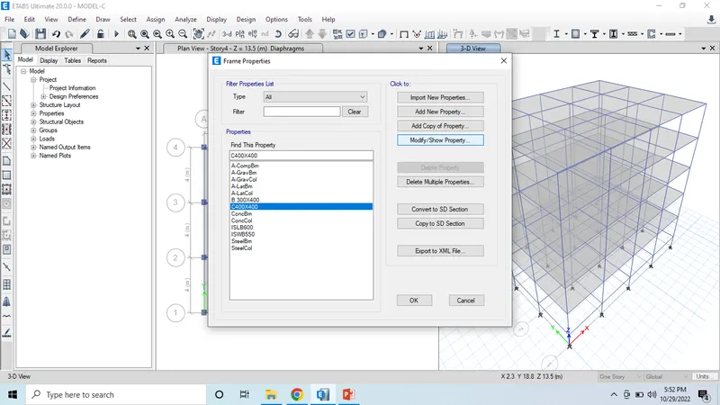
- Give the column size as per the given question.
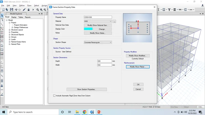
- Now we can see the column size hich we have created.
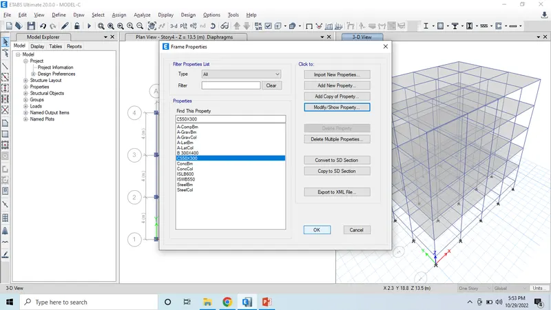
- Now we can see the column sizes are changed to new column sizes.
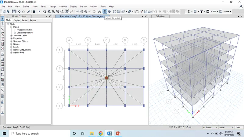
- Now select all the frame sections for beams.
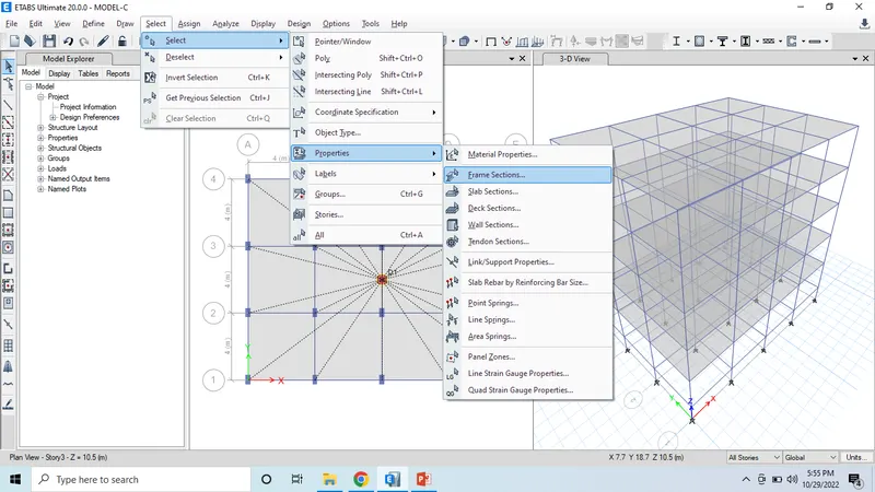
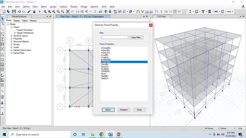
- Select the column size.
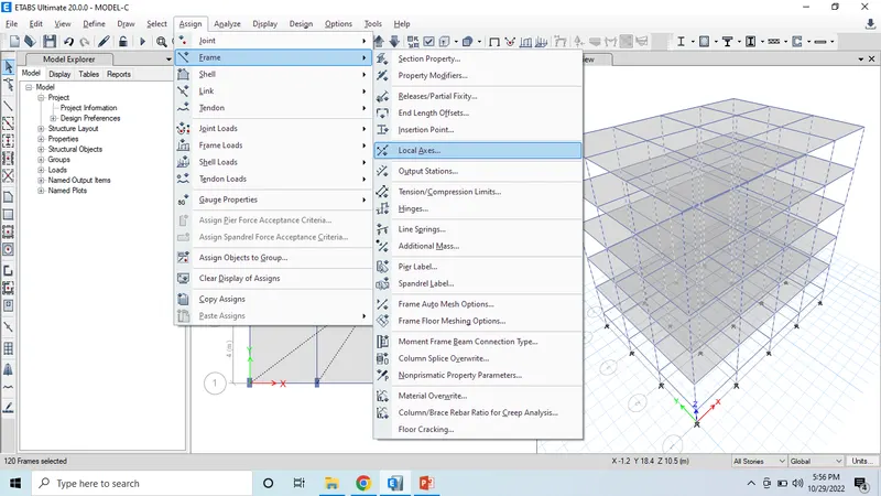
- Now assign the load axes to the columns.
- Then give the angle as 90 for changing the column direction.
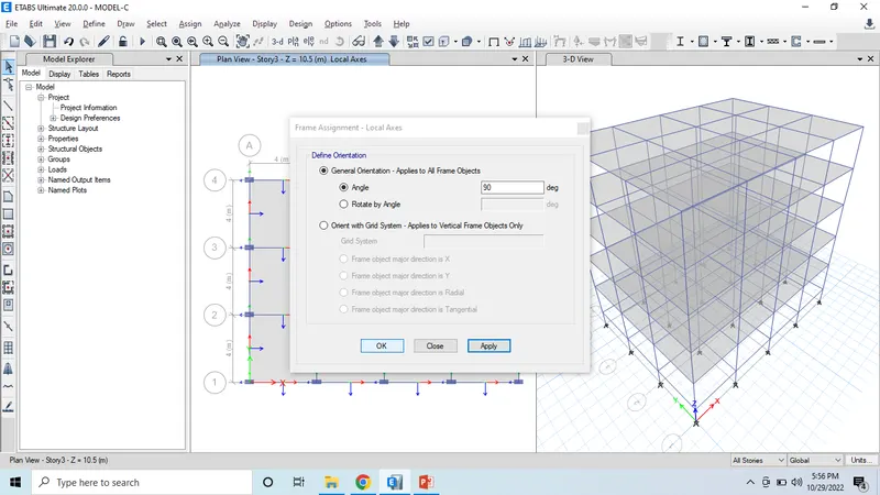
- Here we can see the column positions are changed.
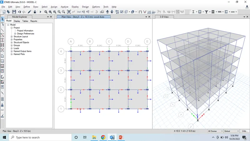
- Now select the slab positiion.
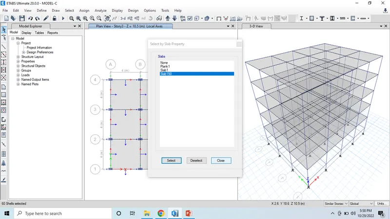
- Apply the diagrapham to the stories.
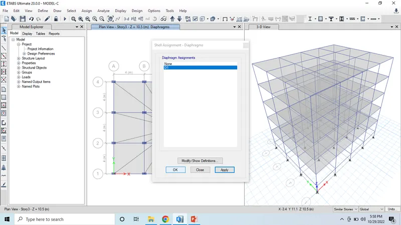
- Now we can see all the slabs with load applied to it.
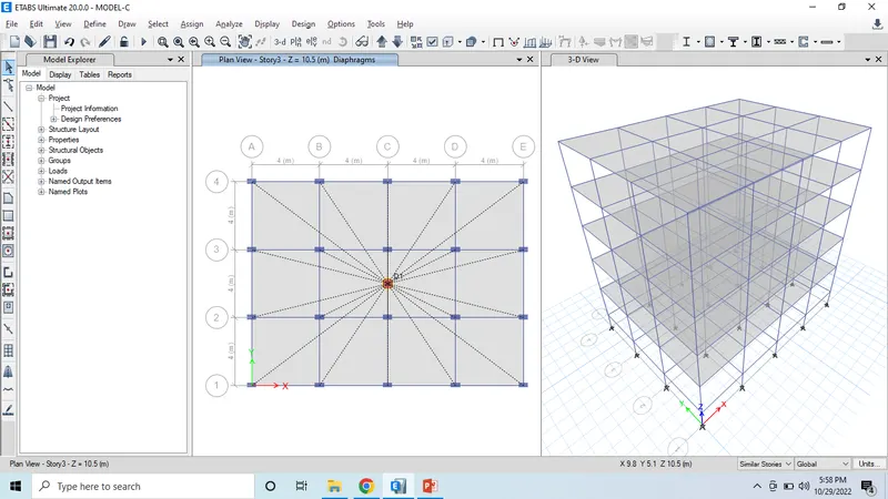
- Click on run analysis option.
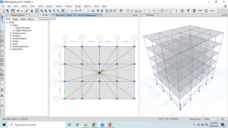
- Finally drawing is ready with all loads applied on it.
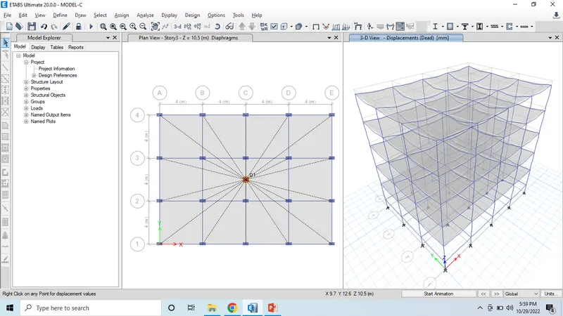
MODEL-D
- Do the file save as to Model-D
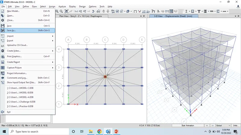
- Click on the select tab and select all the frame sections.
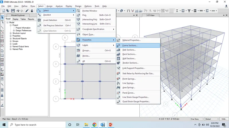
- Now select the column with the given size and click ok.
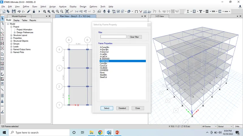
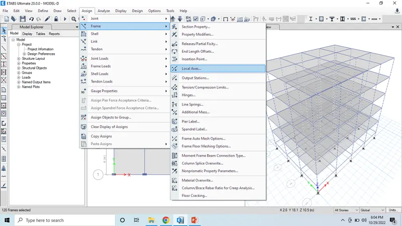
- Now go to assign tab and apply load axes to the columns.
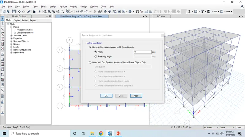
- Give the angle as 0 to change column position.
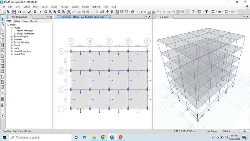
- Now we can see the column orientation.
- Now go to the select tab and select all the slabs.
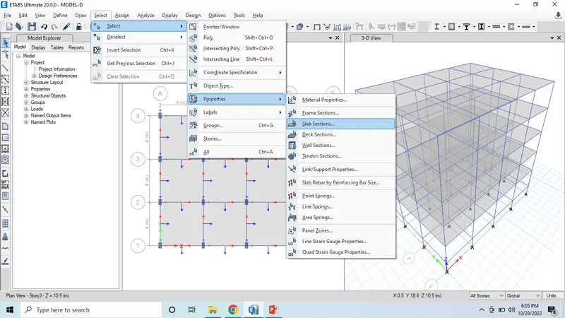
- Select the slab length and click ok.
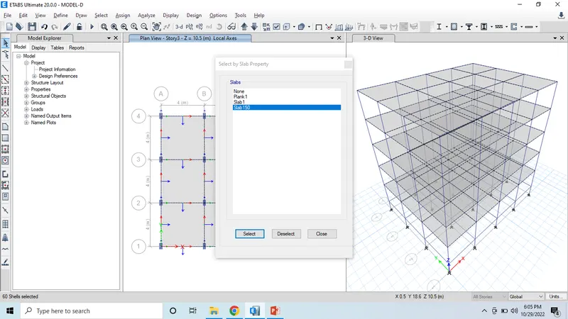
- Assign diaphragam to the slabs.
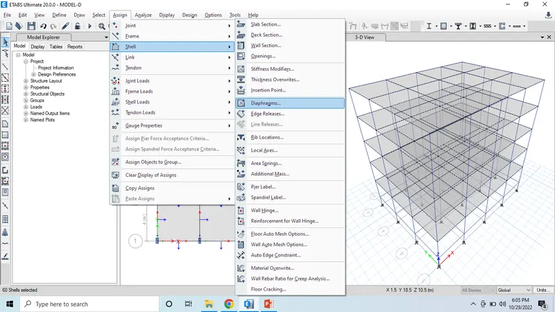
- Select Di option and click ok.
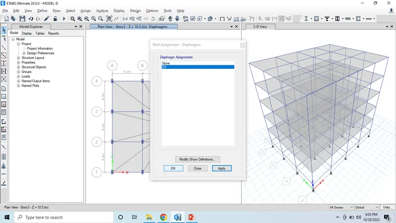
- Now we can see all the loads applied to the slabs.
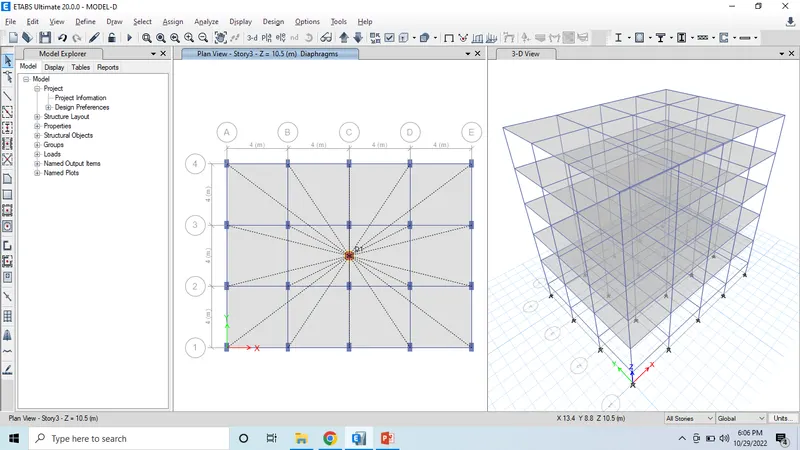
- Click on run analysis option.
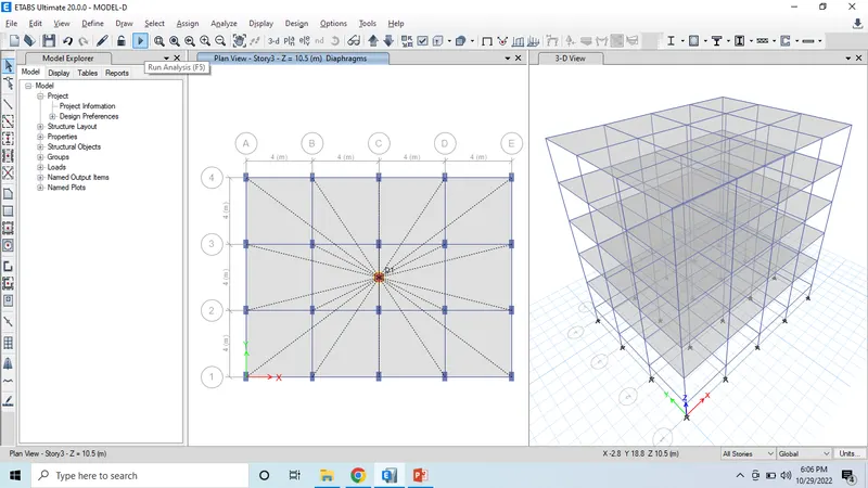
- Now we can see the resuts after the run analysis.
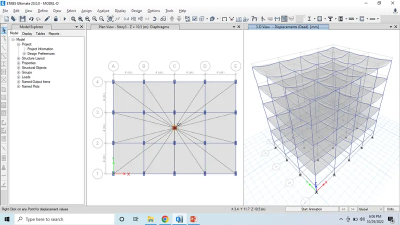
MODEL-E
- Do save as the file as Model-E
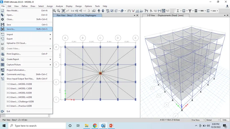
- Now add the stories as per the stories given in the question.
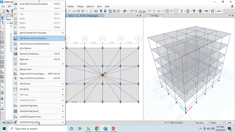
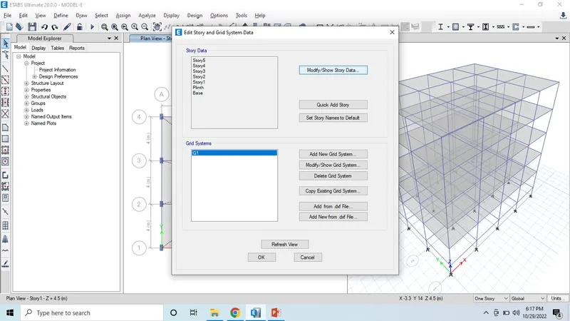
- Click on Modify option.
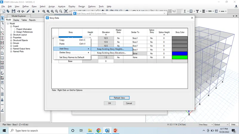
- Right click on the story and select add story option.
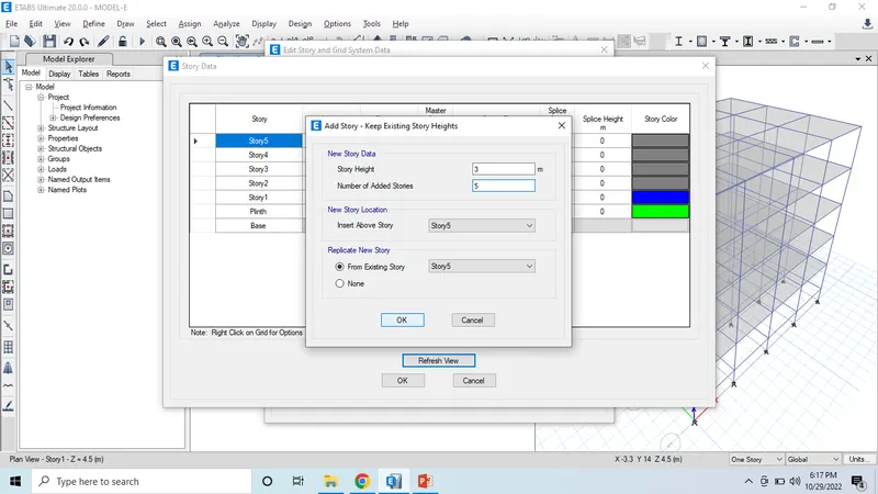
- Give the number to add the stories.
- Now we can see stories added to the grids.
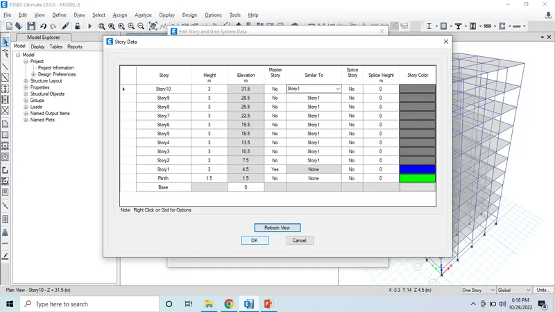
- Now we can see the storeys added.
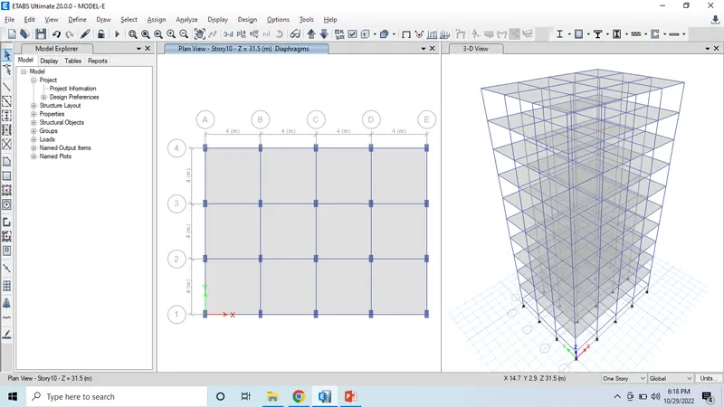
- Check the loads applied on the storeys.
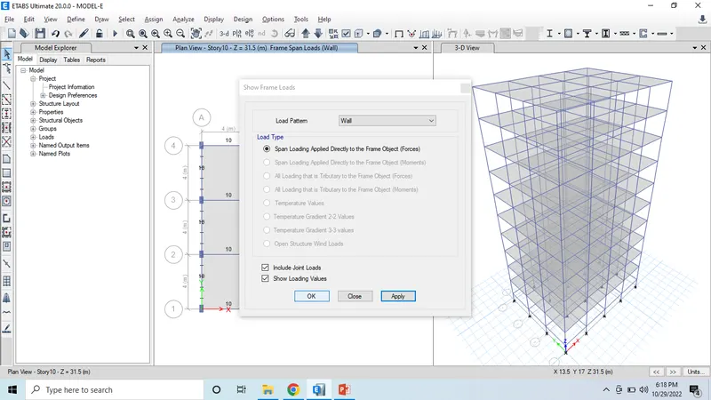
- We can see the loads applied on the storeys.
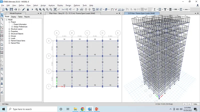
- Check the live load applied on the grids.
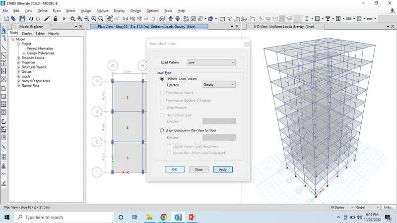
- Now check the wall load applied on the grids.
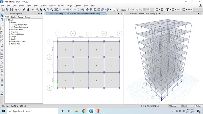
- Go to the define tab and select frame section option.
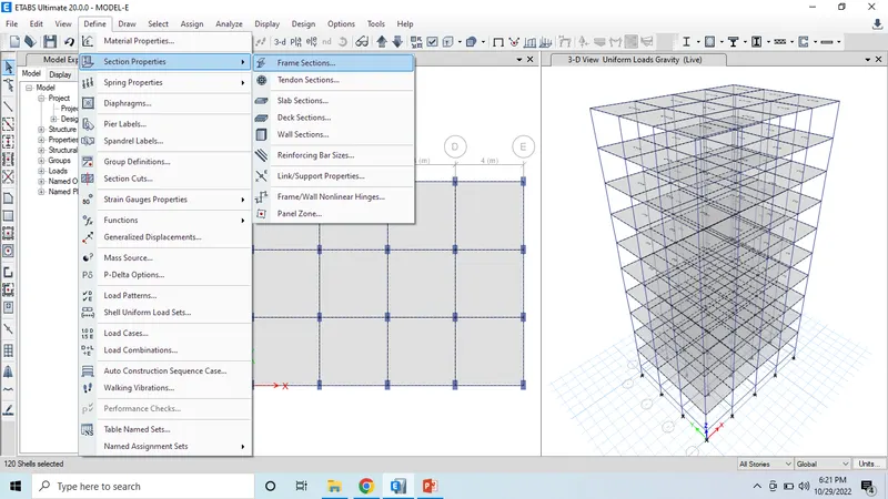
- Now select the column option and click ok.
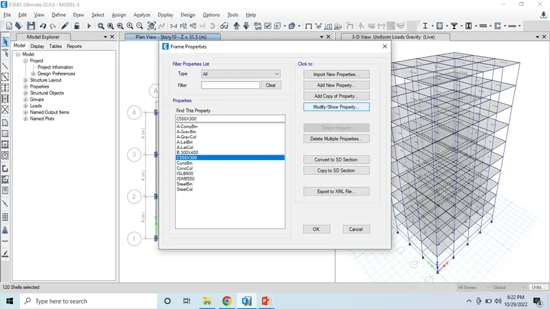
- Change the column size as per the question.
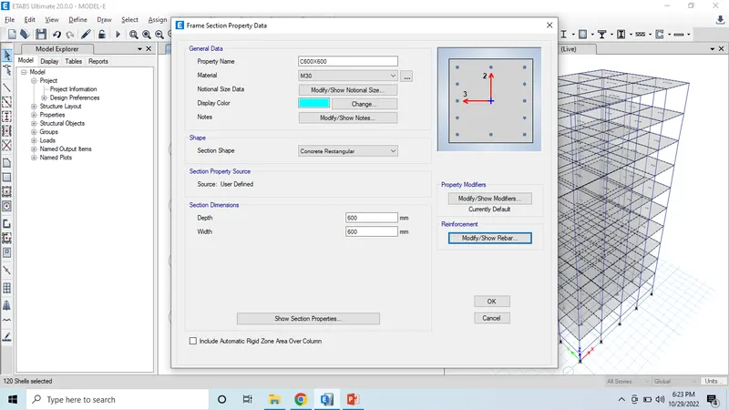
- Select the column and click ok.
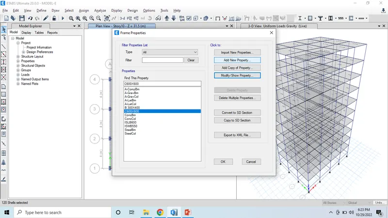
- Click on the concrete option.
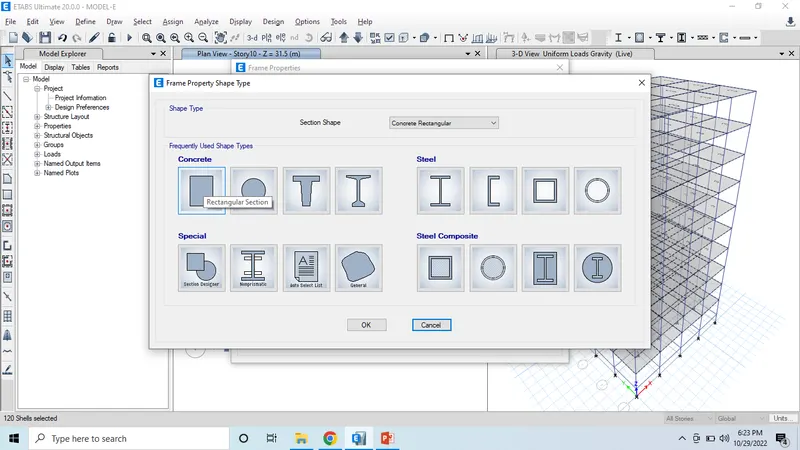
- Change the column size.
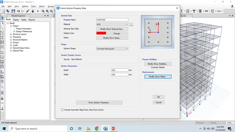
- Click on the add story option.
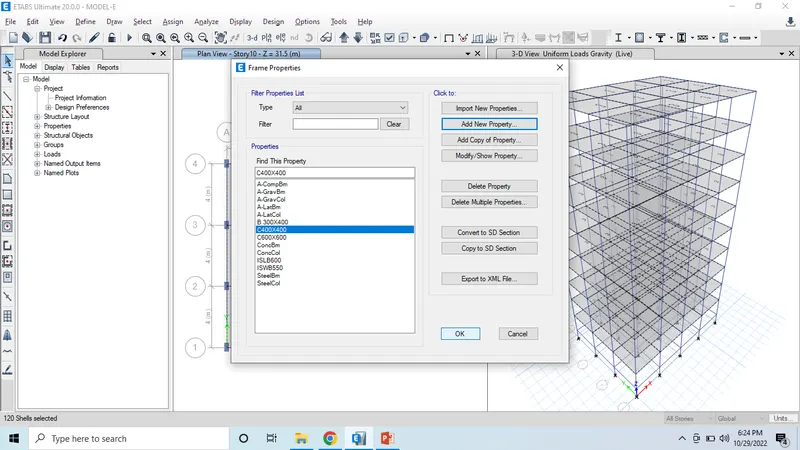
- Now unselect the beams and floors and click ok.
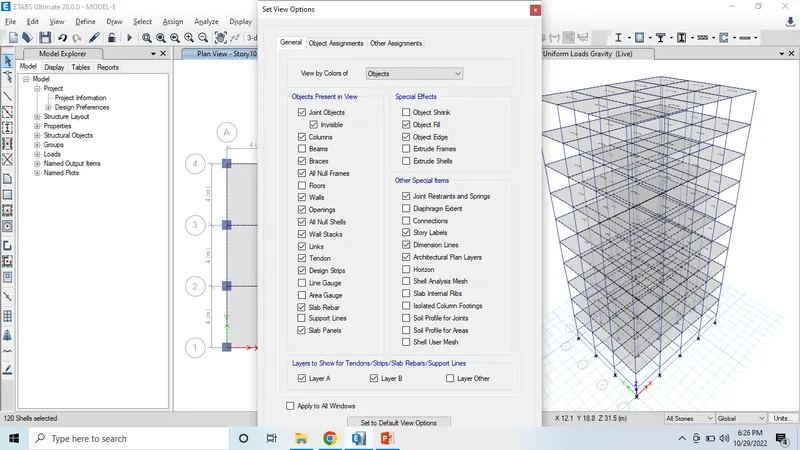
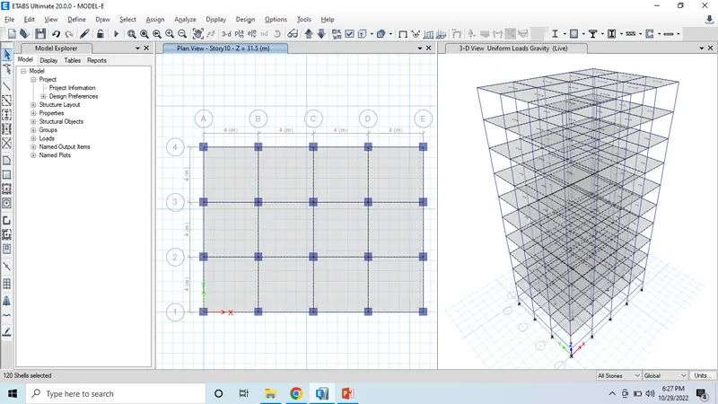
- Now we can see the unhide of beams and columns.
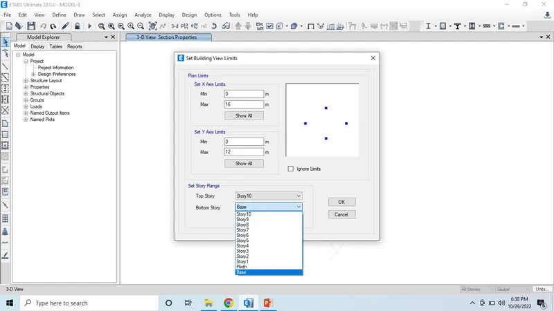
- Now set the building limits by selecting building limits option.
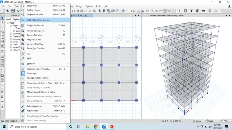
- Select the story height options.
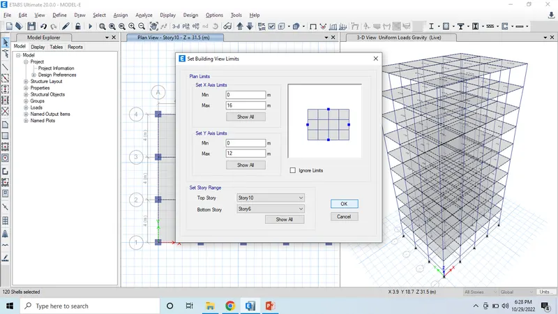
- Now we can see the selected columns.
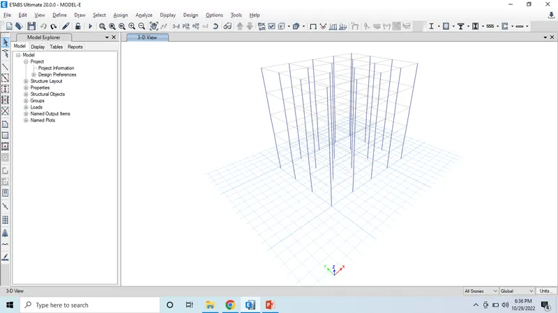
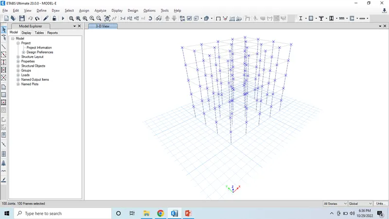
- Select all the columns.
- Now go to assign option and select section property option.
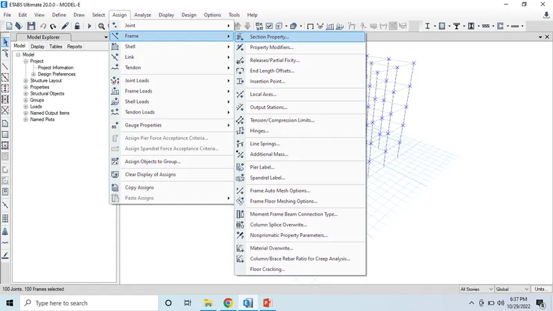
- Select the column position.
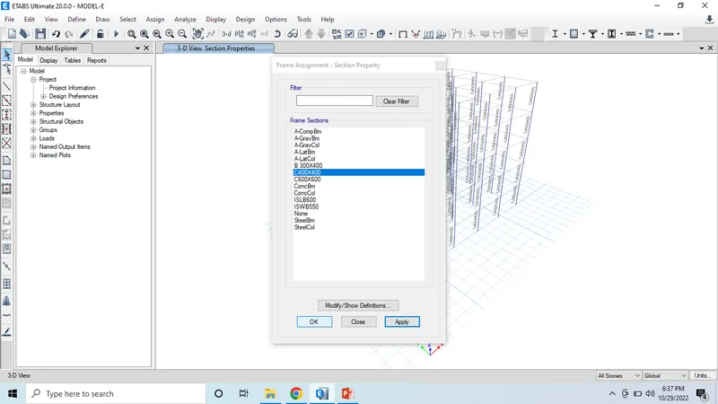
- Now we can see the columns assigned to the grids.
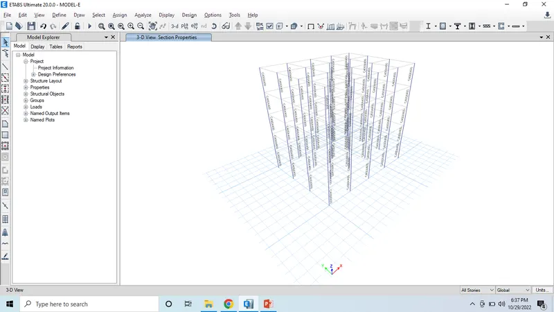
- Again change the building story limits.
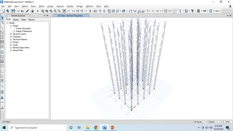
- Now we can see all the columns with the given column sizes.
- also we can see in the plan of column assigning.
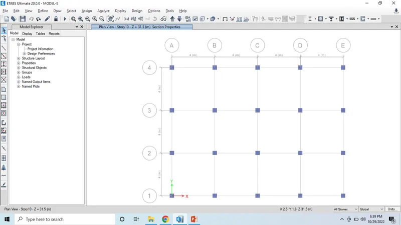
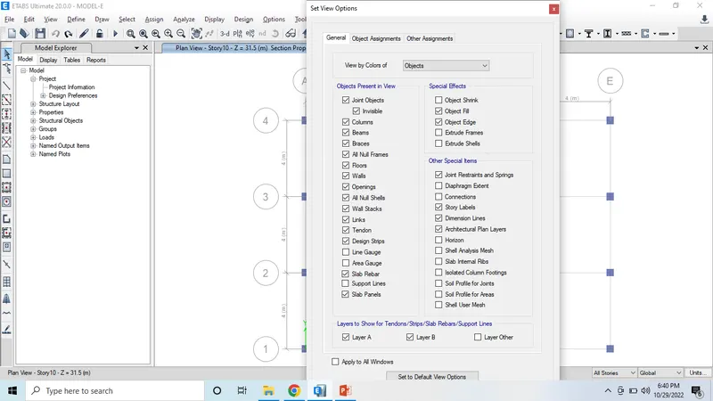
- Now unselect the beams and floor to view in the drawing.
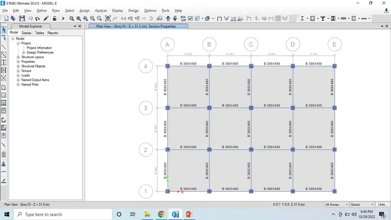
- We can see the beam sizes assigned to the grids.
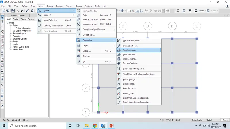
- Now go to the select option and select slab position.
- Now go to the assign option an apply diphragram.
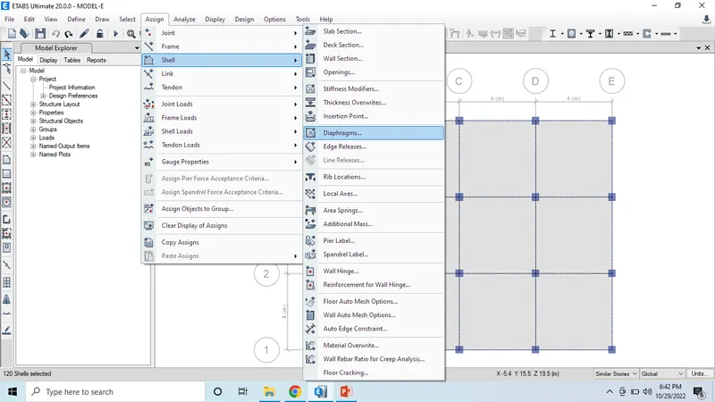
- Here we can see the diphragram applied on the drawing.
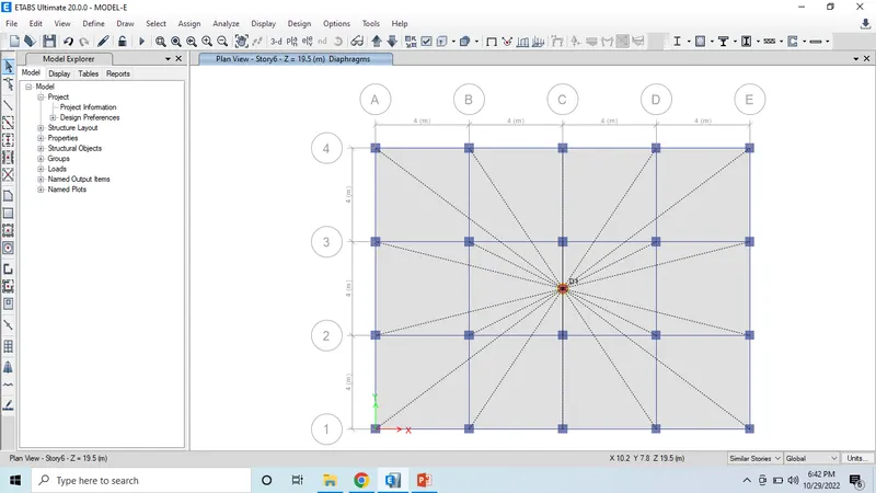
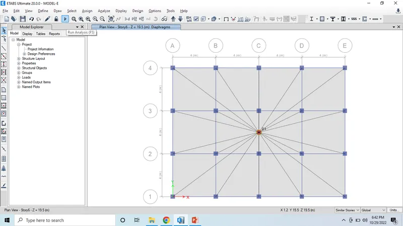
- Click on the run analysis.
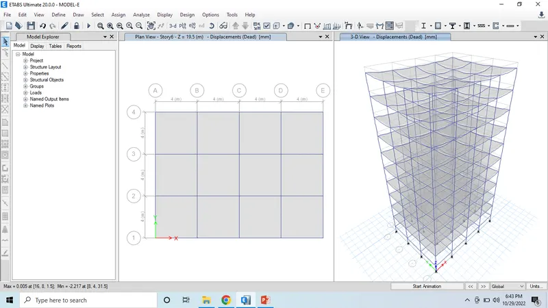
- Final we can see the result applied on the grids.
MODEL-F
- Do the file save as as model-f.
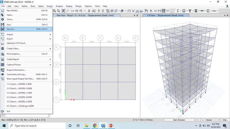
- Now set the boundary limit option and click ok.
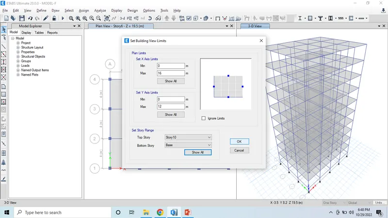
- Now hide the beams and floor option.
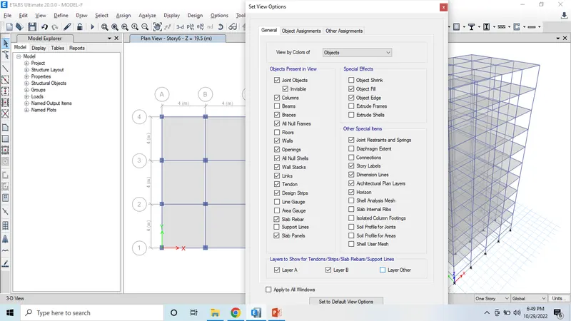
- Now select all the columns on the 3d view.
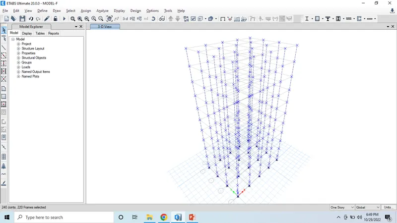
- Now assign section property.
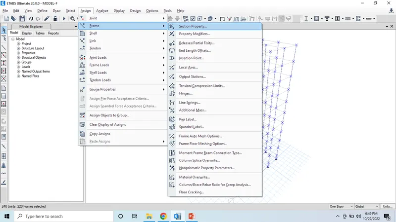
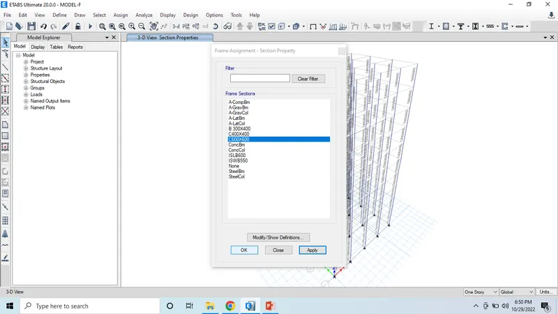
- Select the column option and click ok.
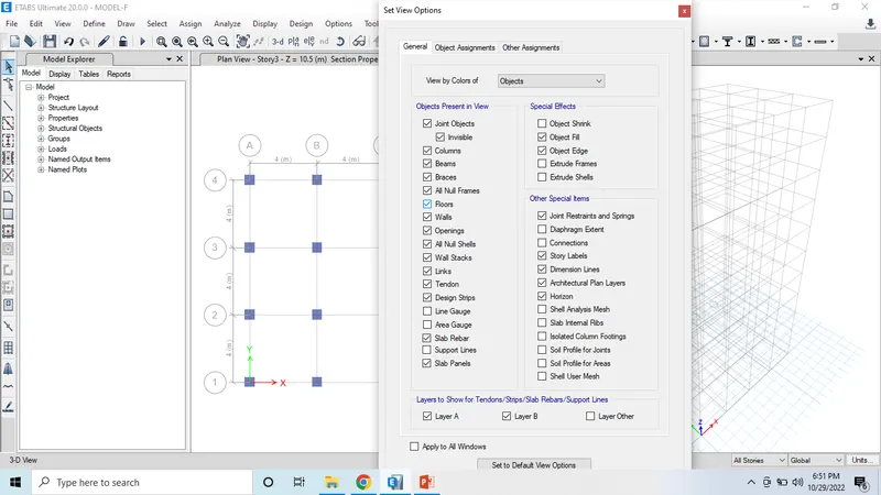
- Now do unhide option for beams and floors.
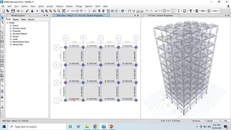
- Here we can see the column size applied on the grids.
- Go to the select option and select slab portion.
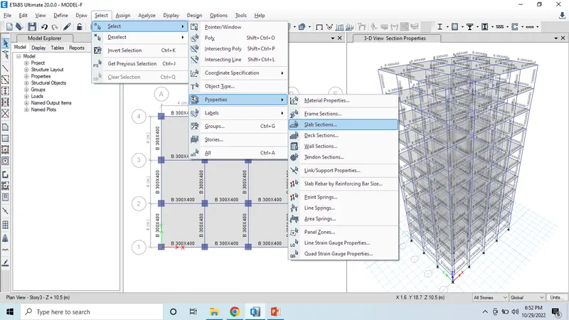
- Assign diphragam to the slab.
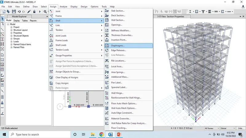
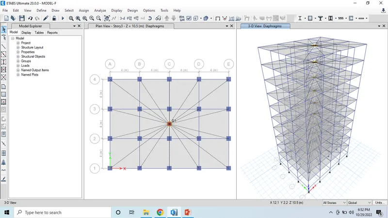
- Here we can see the dipragam applied on the grids.
- Click on run analysis option.
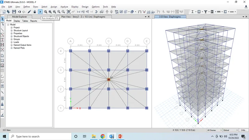
- Final diagram is ready in the grids.
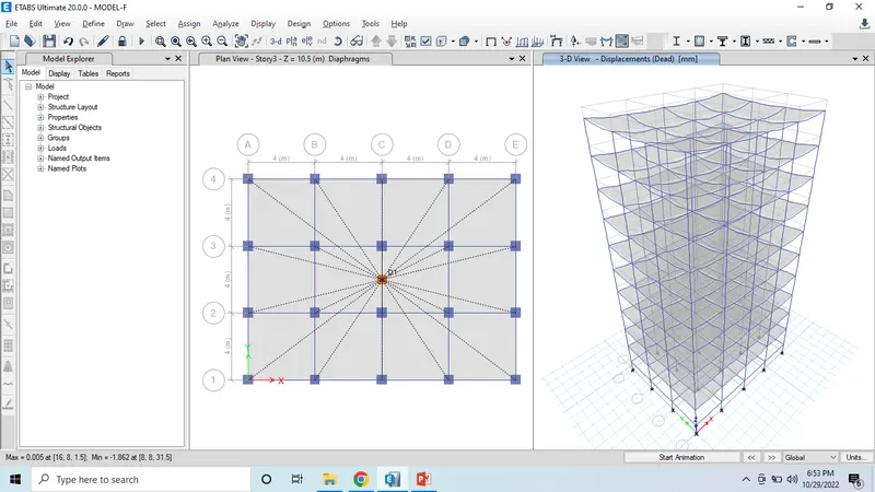
MODEL-G
- Do save the file as save as option.
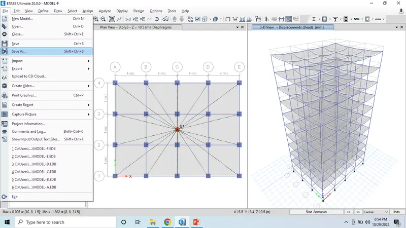
- Now select the add story option and add the stories.
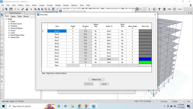
- Give the number to add the stories.
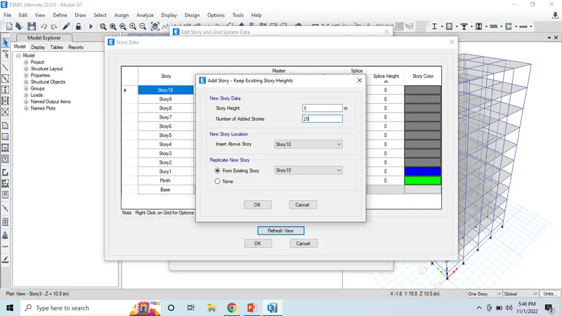
- Here stories are added to the grids.
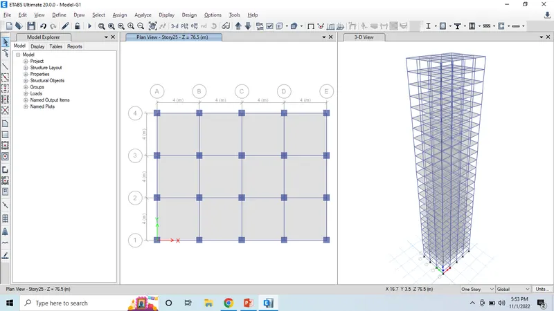
- Now check the loads applied to the grids.
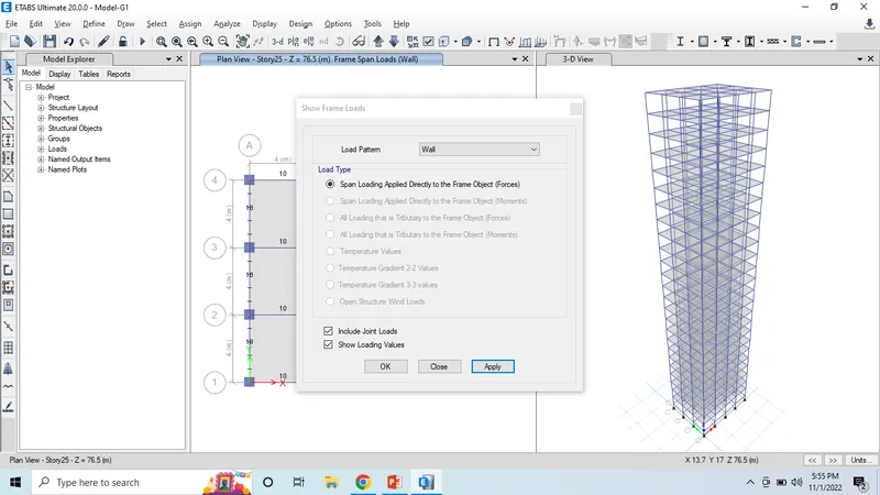
- here we can see the waall load applied to the beams.
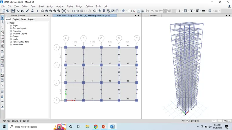
- Now all the loads are applied to the grids.
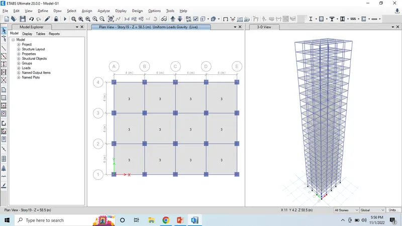
- Go to define option and selet the frame section.
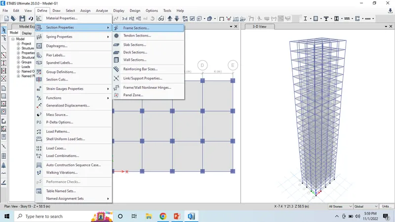
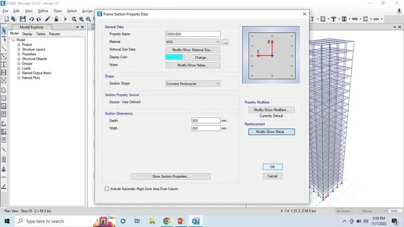
- Change the column sizes as per the given question.
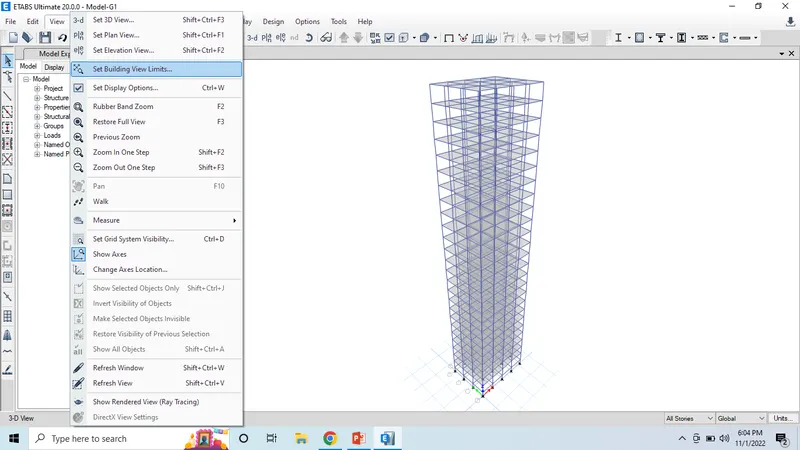
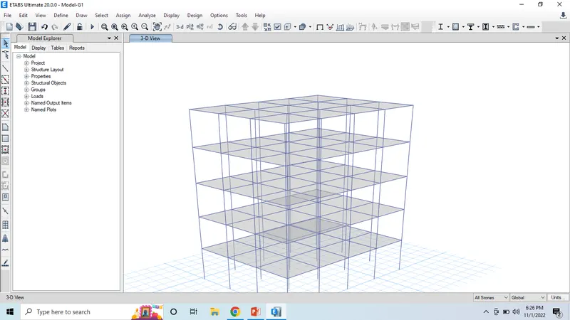
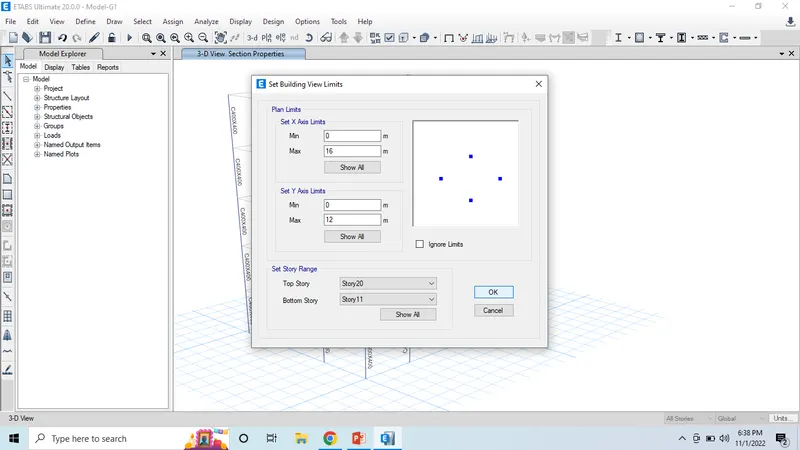
- Now set the building view level options.
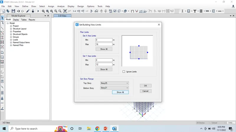
- Give the number stories to the top and bottom stories.
- We can see the selected columns on the grids.
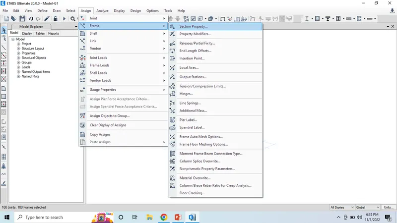
- Go to the assign option and select section property.
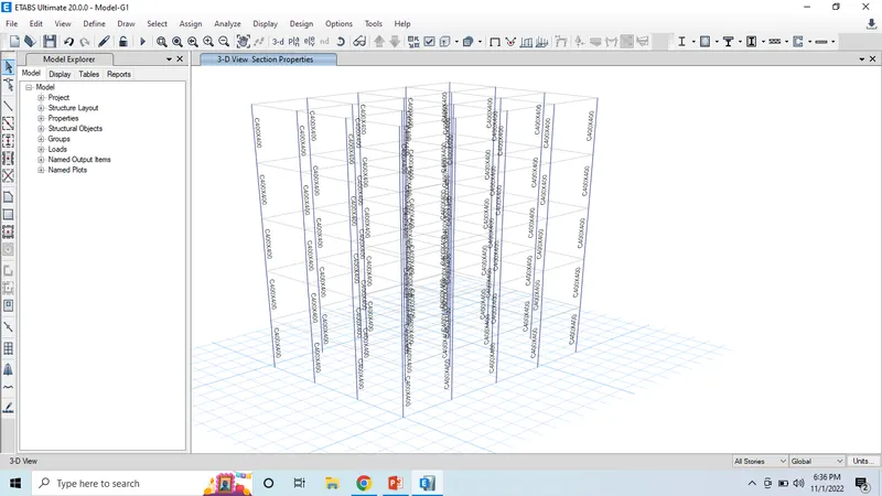
- Here we can see the column sizes assigned.
- Select the stories for the second list on the grids.
- Now assign the section property load.
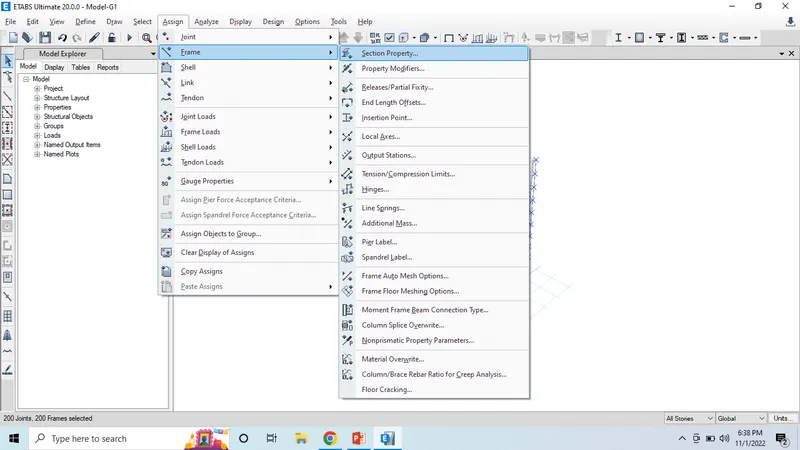
- Now select column size and click ok.
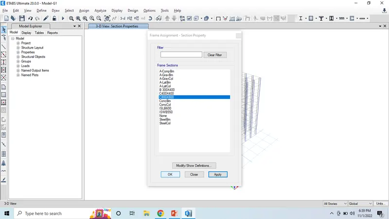
- Here we can see columns assigned to the grids.
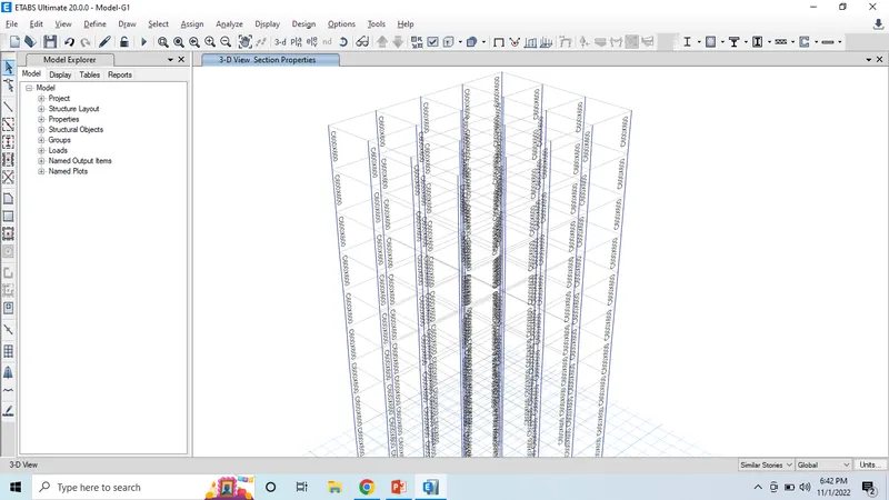
- Here we can see the columns size assigned to the girds.
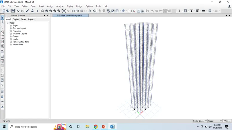
- Click on the run analysis option.
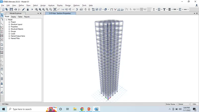
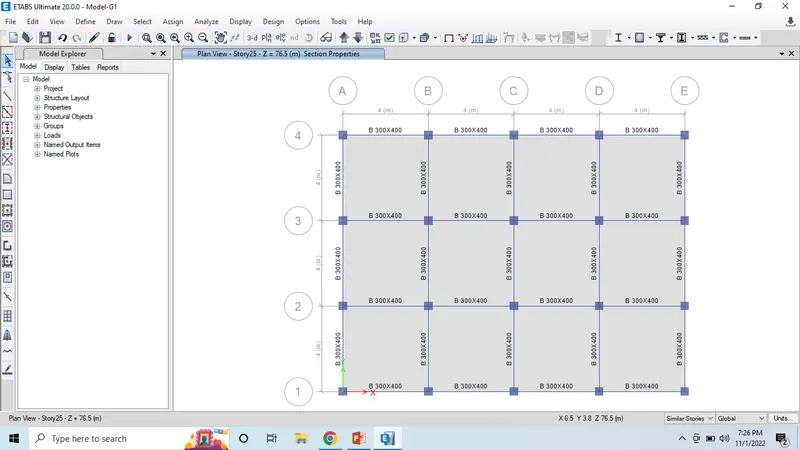
- columns are assigned to the grids in the plan view.
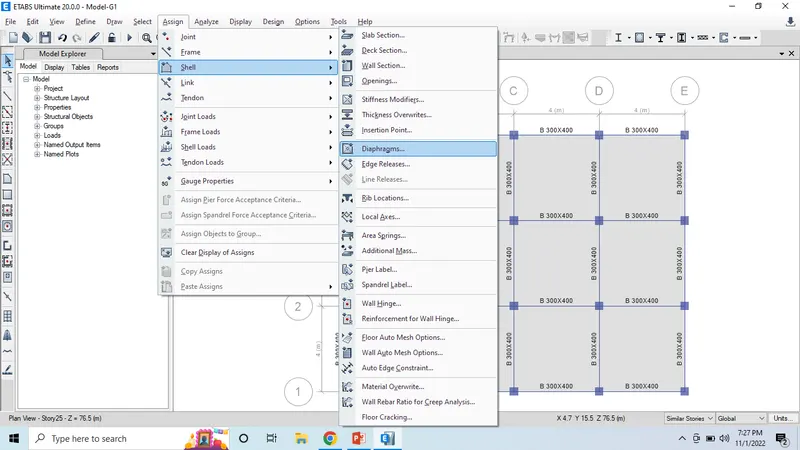
- Now assign dipragram to the slabs.
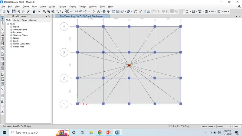
- Here is the final drawing
Model-H
- Do save as the file with the model-h name.
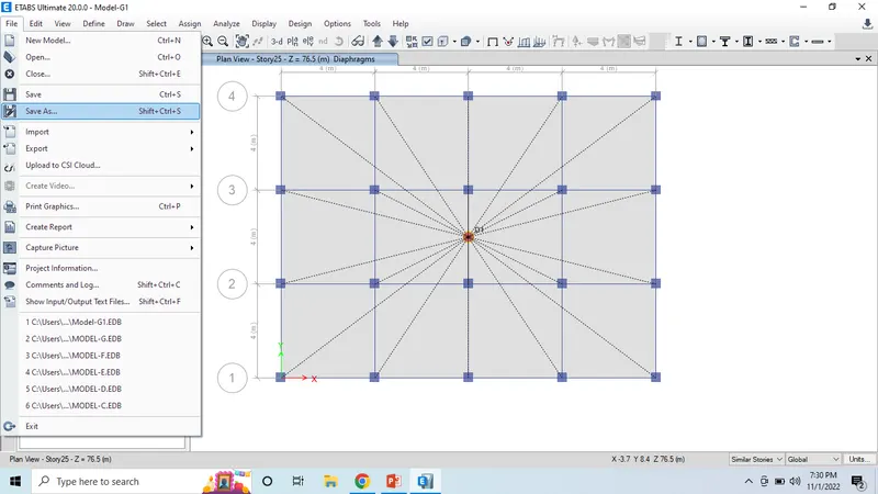
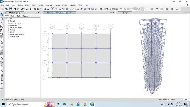
- Now we can see the plan and 3d view of the drawing.
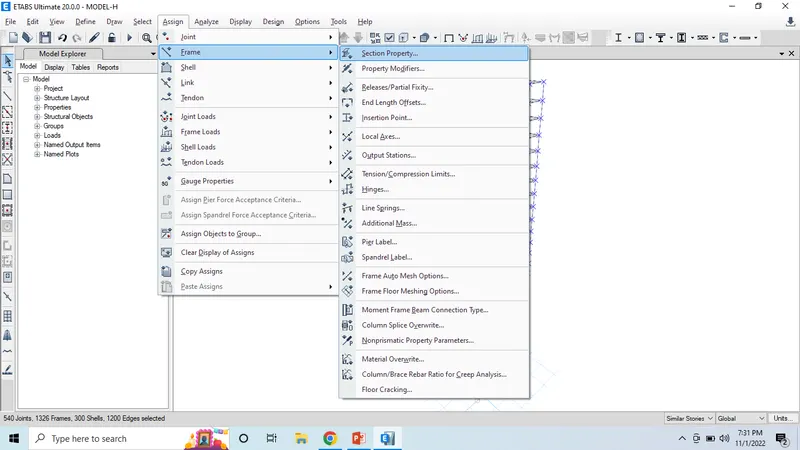
- Now assign the section property for the grids.
- Here we can see the 3d view of the storeys.
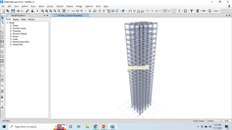
- Now we can see the columns assigned in the plan view.
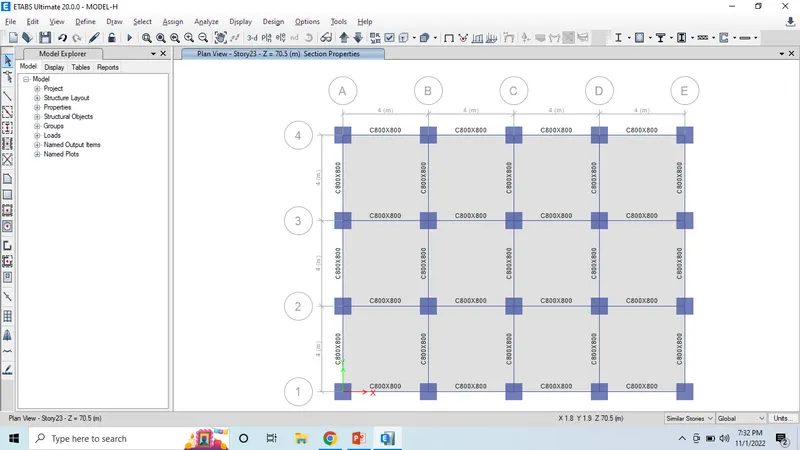
- Check the loads assigned to the grids.
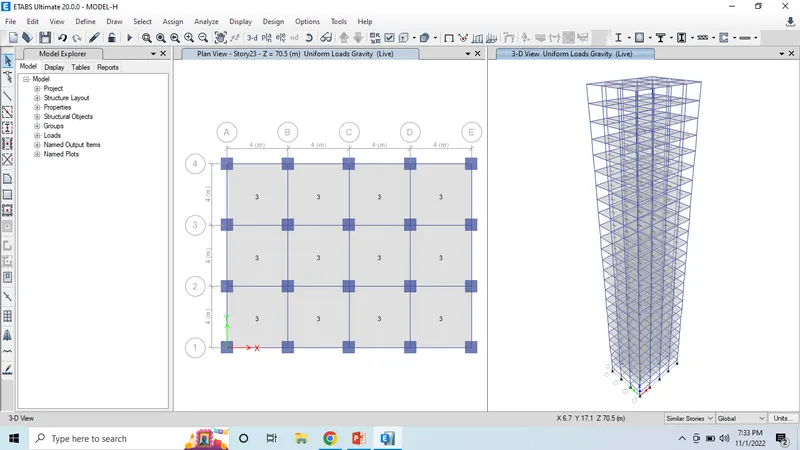
- Now assign the slab diphragram to the slabs.
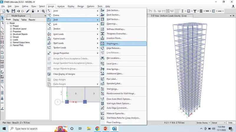
- Now loads are assigned to the slabs.
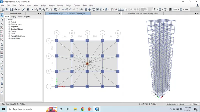
MODEL-J
- Do save as the file with the other name.
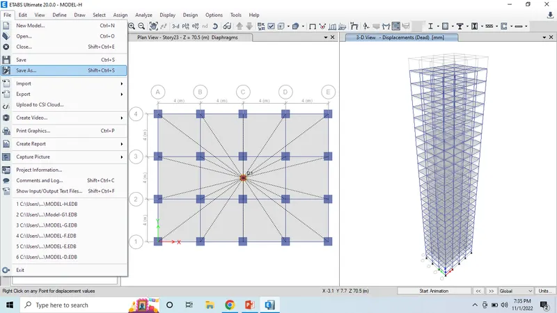
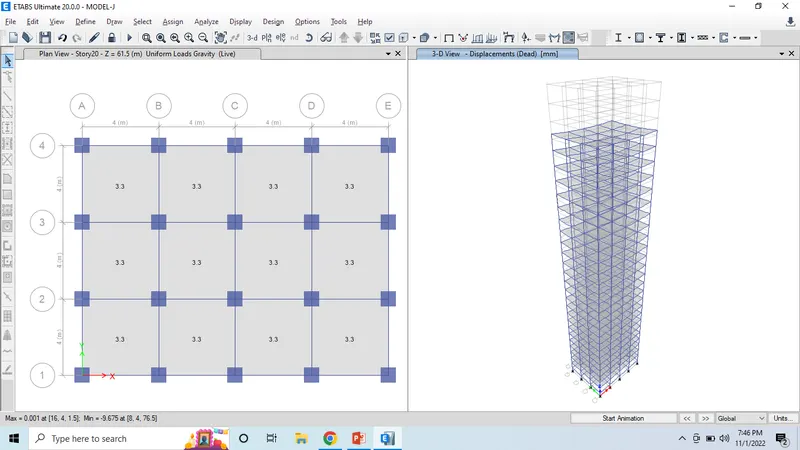
- Now take the 3d view of the drawing.
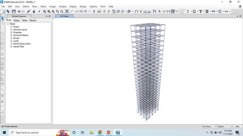
- Now assign the loads to the slab for uniform distributed load.
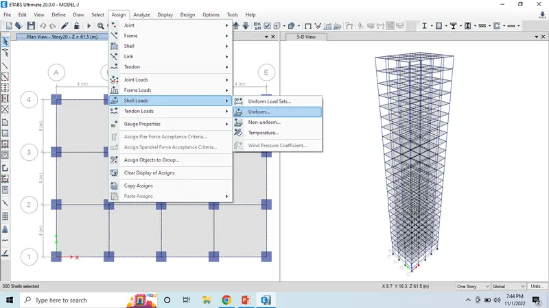
- Give the loads for live load as 3.3kn/m.
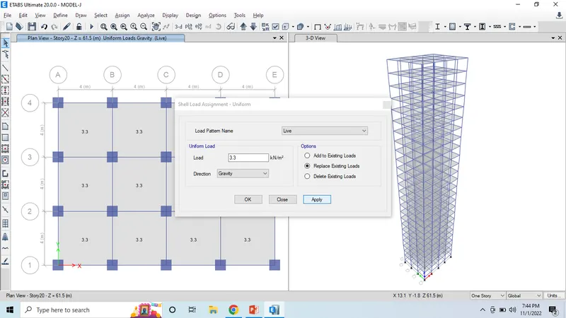
- Here we can see the loads assigned to slabs for live loads.
MODEL-K
- First we have to save as the file for the previous file.
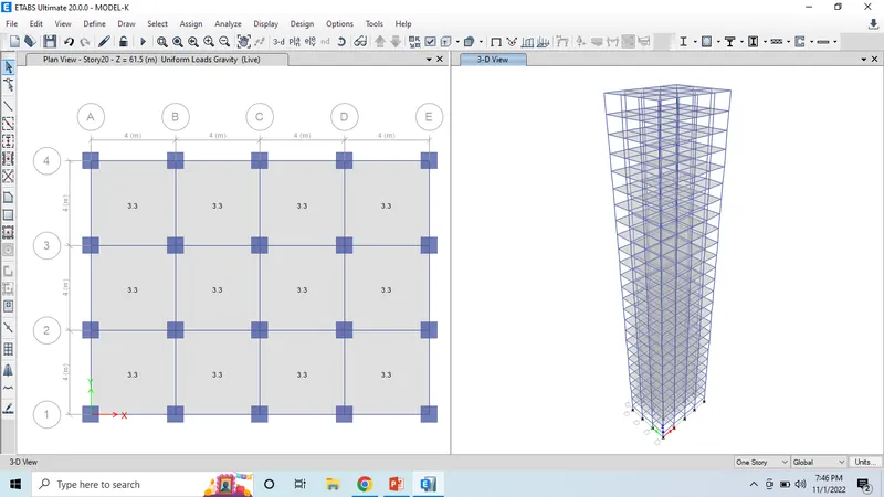
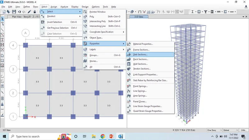
- Now select the all slabs by using select tab option.
- Now assign the slabs portion as uniform distributed loads.
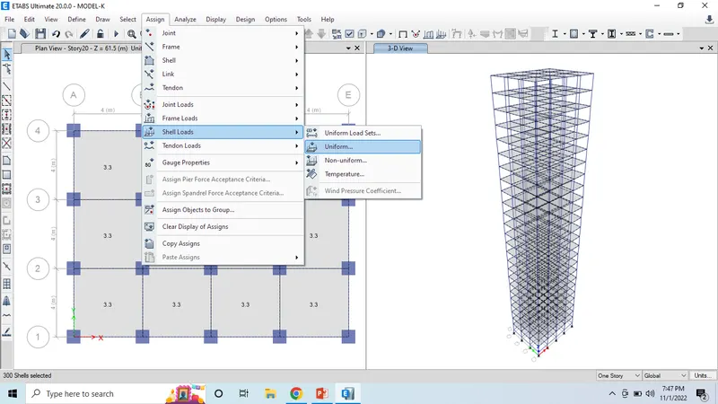
- Now loads are applied to the slabs.
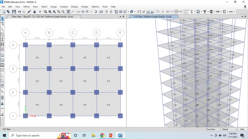
- Clearly we can see the loads applied for both plan and 3d view.
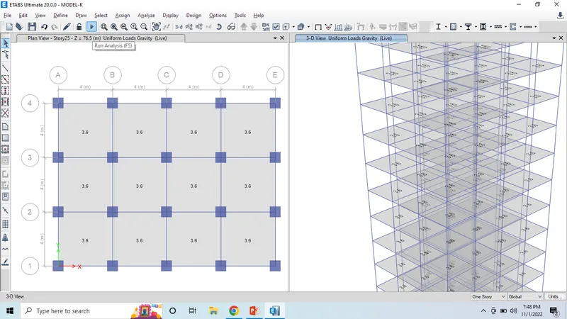
- Final drawing is ready for all the slabs assigned.
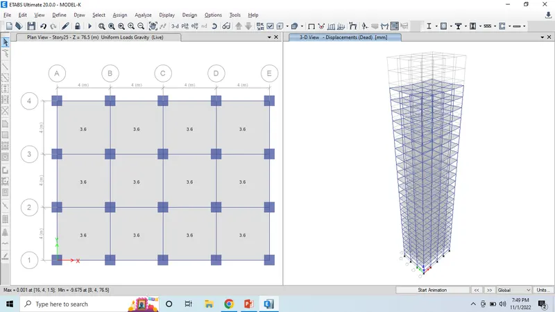
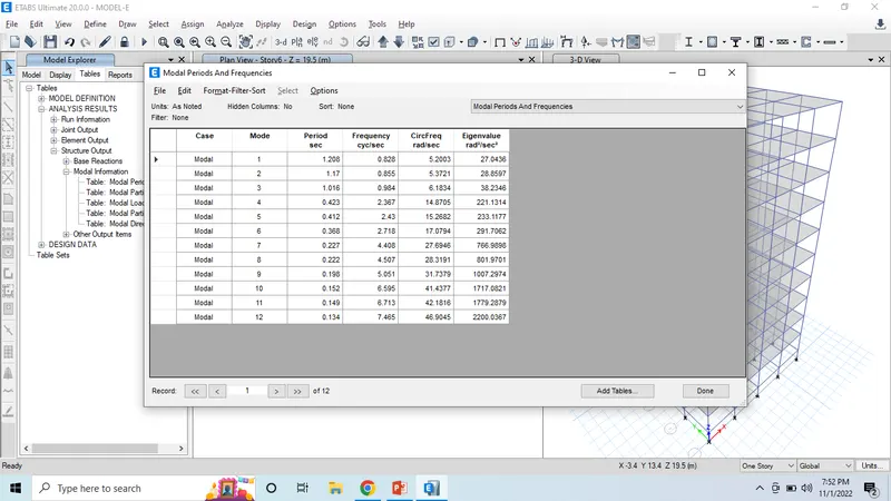
MODEL E TABLE FOR MODEL TABLE AND FREQUENCIES.
- Select the table from analysis and results.
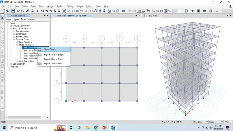
- Here we have the period sec as 1.20 from the table.
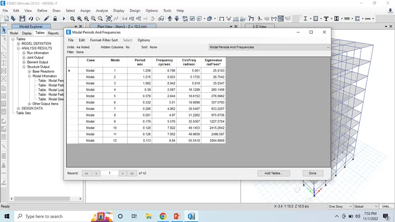
MODEL F
- In the same way take the load for model f for model periods and frequencies.
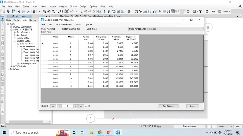
MODEL-G
- In the same way take the load for model g for model periods and frequencies.
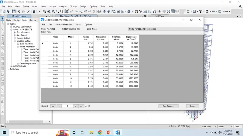
MODEL-H
- In the same way take the load for model H for model periods and frequencies.
MODEL J
- In the same way take the load for model J for model periods and frequencies.
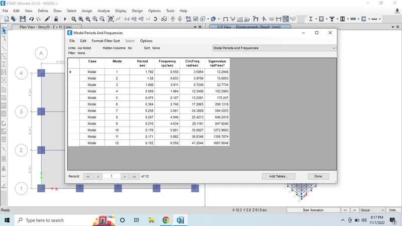
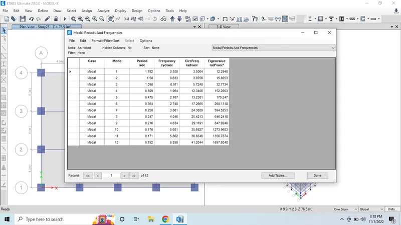
MODEL K
- In the same way take the load for model K for model periods and frequencies.
EFFECT OF TIME PERIOD FOR BUILDING A
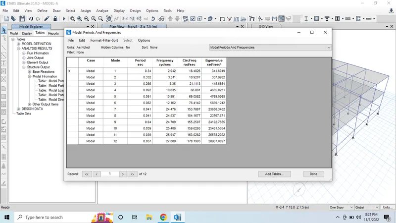
MODEL B
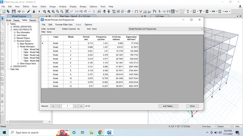
MODEL F
MODEL H
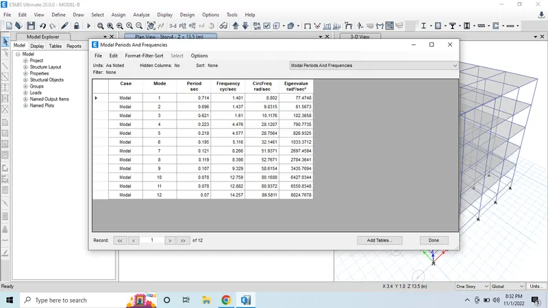
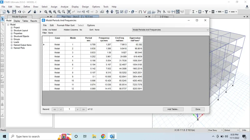
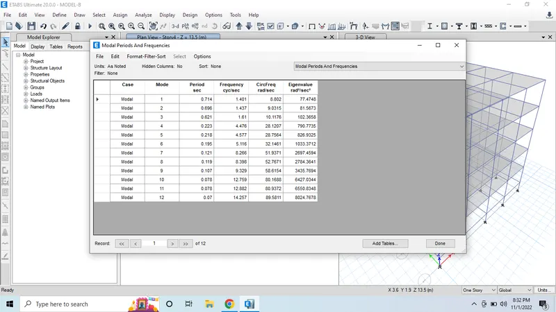
MODE FOR TIME PERIOD
MODEL B
MODEL C
MODEL D
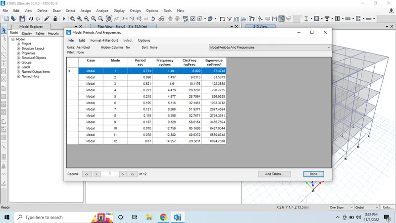
DEFORMATION CHECK:
- Now select modal 1 option.
- Select the mode option.
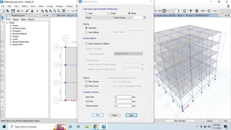
- Select apply and click ok.
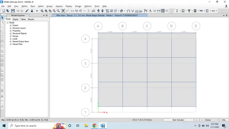
- In the same way select for mode 2 option.
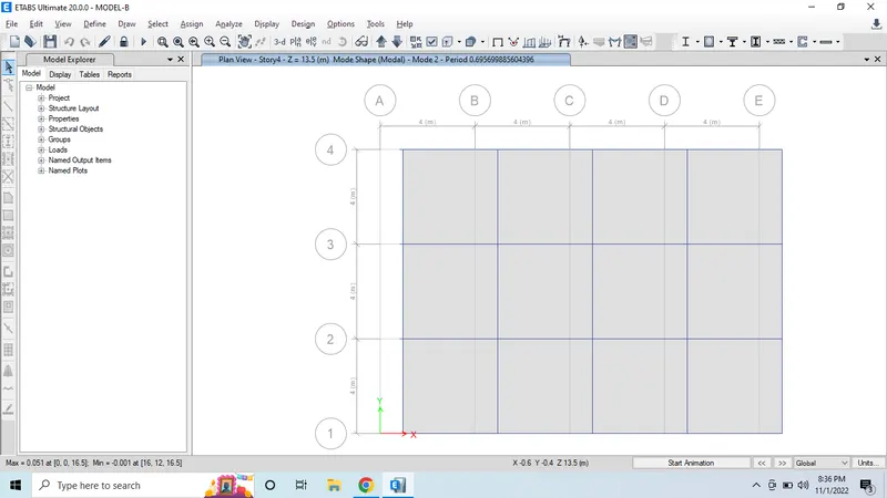
- In the same way select for mode 3 option.
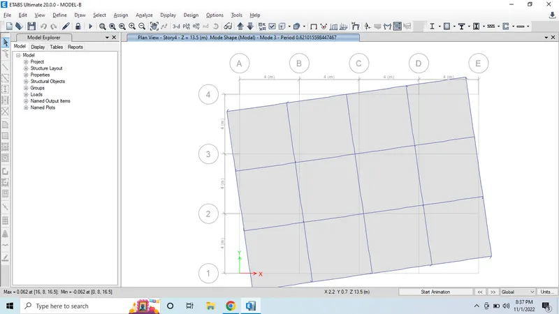
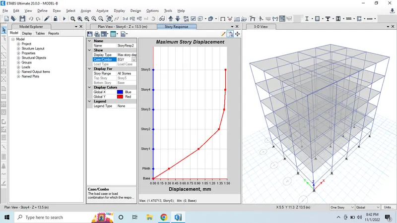
FOR BUILDING B LATERAL LOAD CASES
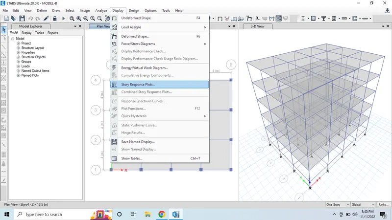
LATERAL LOAD IN X DIRECTION
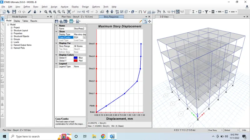
DISPLACEMENT IN Y DIRECTION
MODEL C
lateral load for X-DIRECTION:
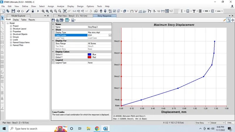
Displacement in Y-DIRECTION
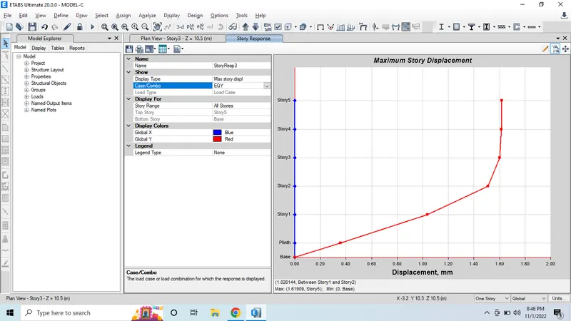
EFFECT OF FLEXURAL STIFFNESS IN MODEL B
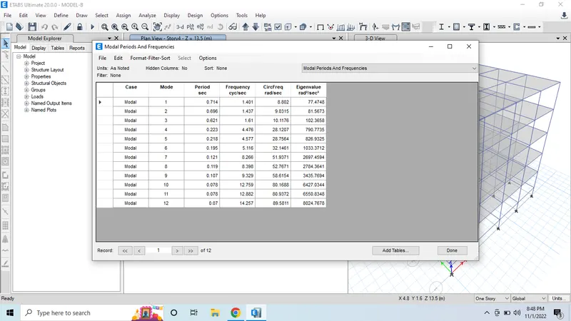
FLEXURAL STIFFENESS FOR MODEL B TIME PERIOD