Project 1_Comparative study of different storey buildings for Seismic forces
Aim:The main aim of this project is to make the different models in e-tabs software and comparing the results of models such as factors influencing on time period.
Introduction:
in this, i am gonna create the different models as given in question and the results are also compared with each other. the details are given in the question,
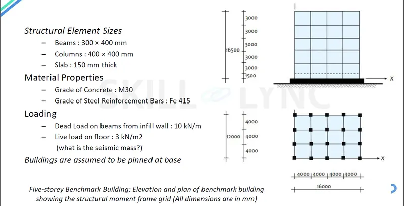
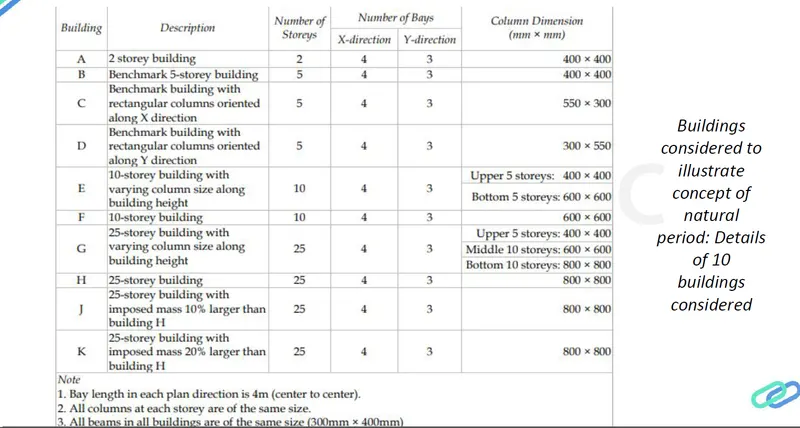
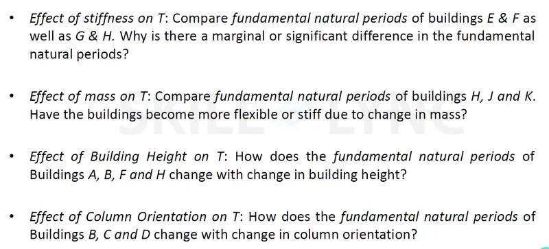
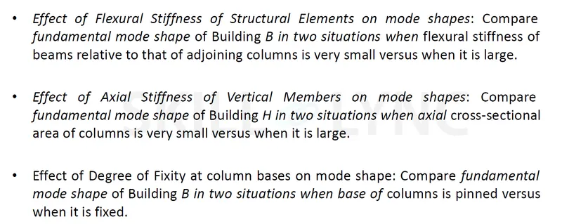
the details need to compare
Procedure:
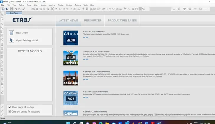
- starting with the model
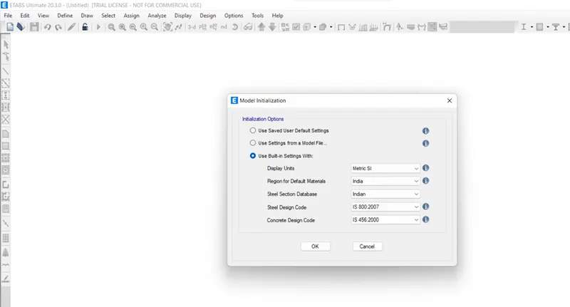
- setting up the initialization as shown below
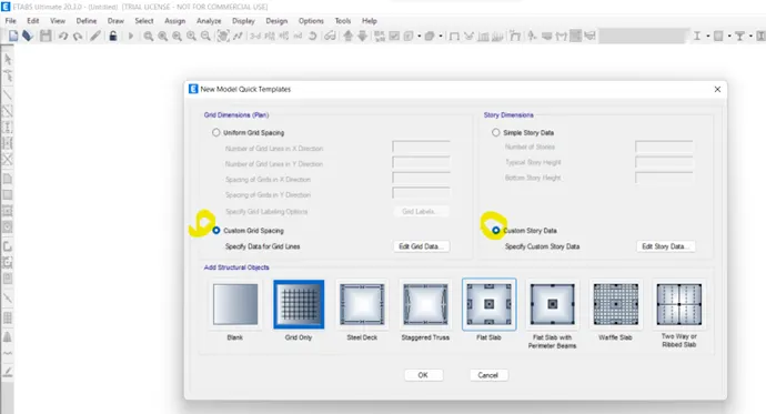
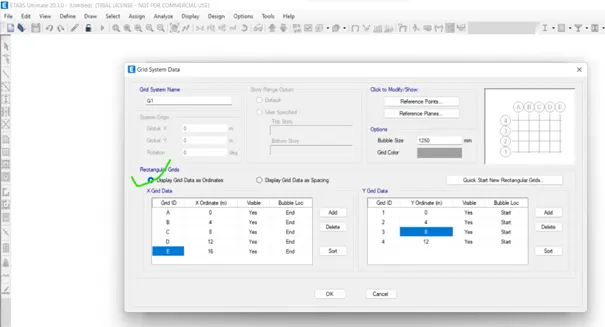
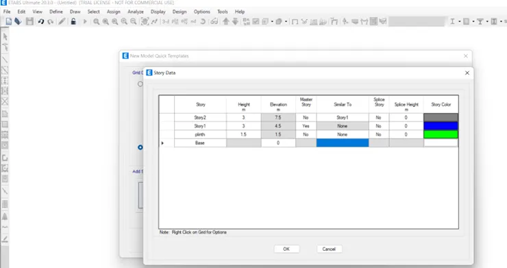
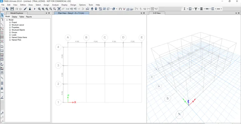
- editing the custom grid and story details as shown below. the grid distance is 4m from one to another and 5 grids in x-direction and 4 grids in y-direction as shown below. the stories are 2 with base and plinth. plinth height is 1.5m and 3 meter distance between stories from plinth as shown below.
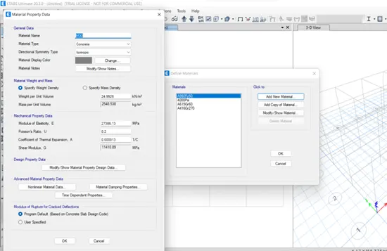
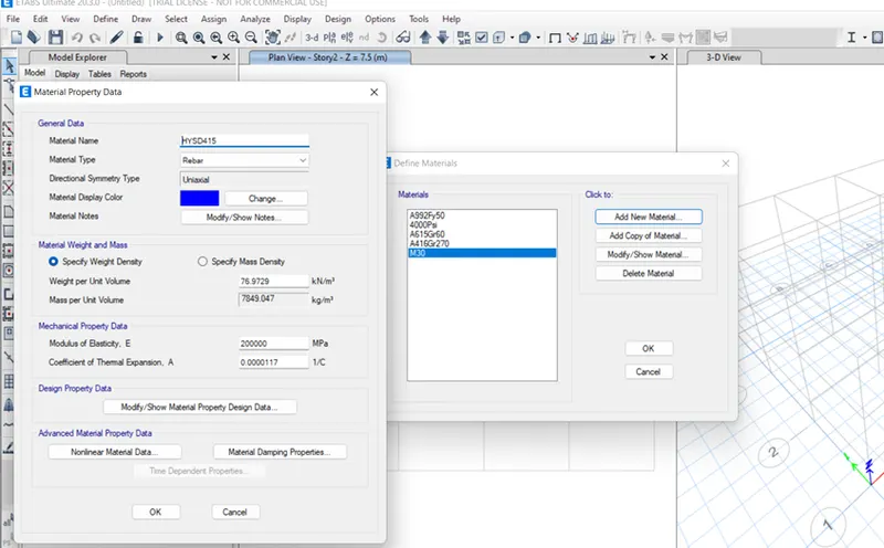
- defining the materials such as concrete-M30 and steel-rebar hysd415 as shown below
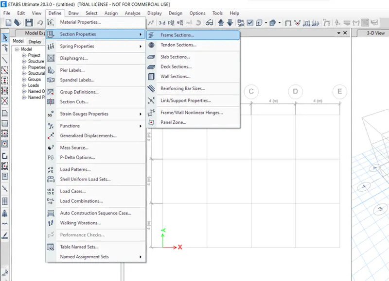
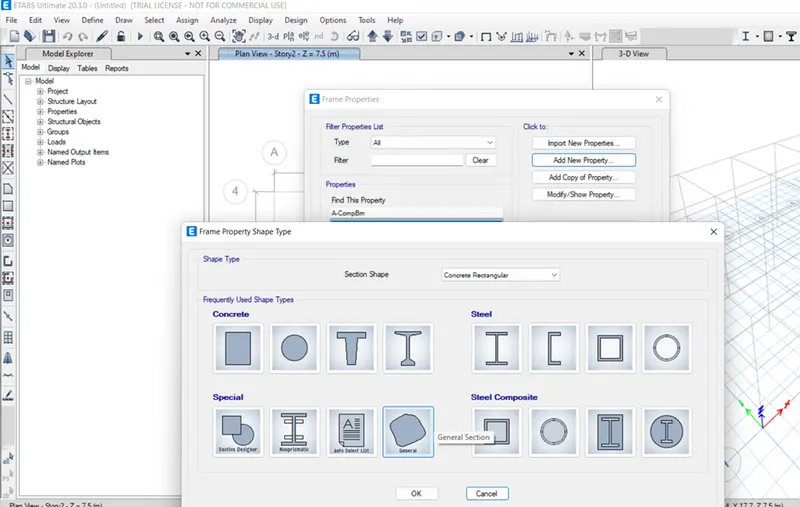
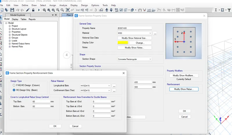
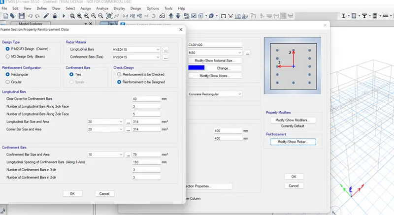
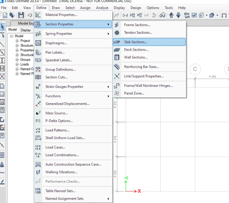
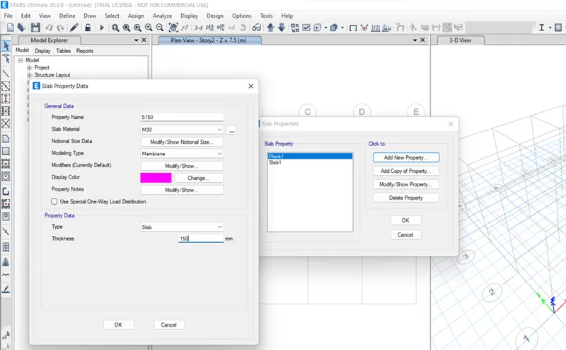
- also defining the section properties having the frame sections and slab section. the frame section having the beam 300mm*400mm and column 400mm*400mm. the slab section having the 150mm thickness.
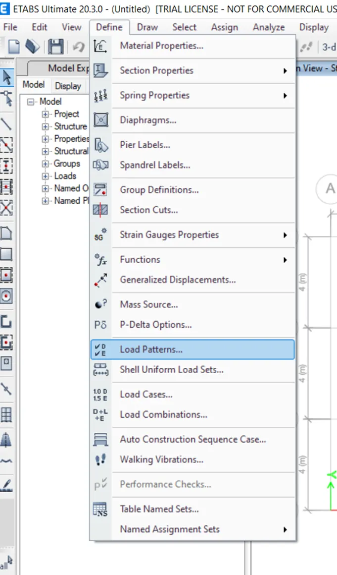
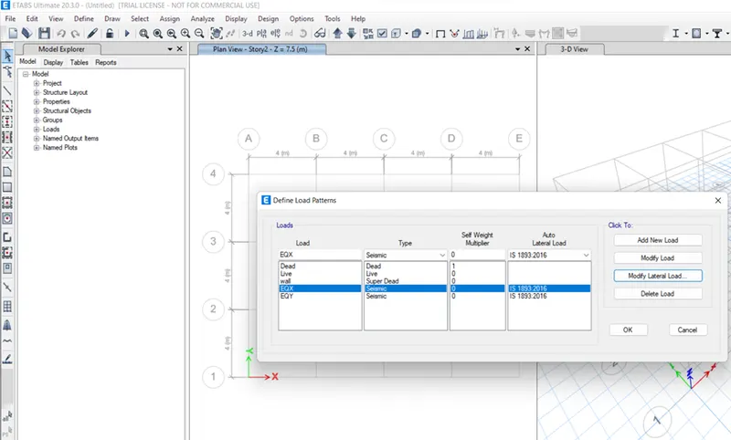
- defining the load patterns as shown below
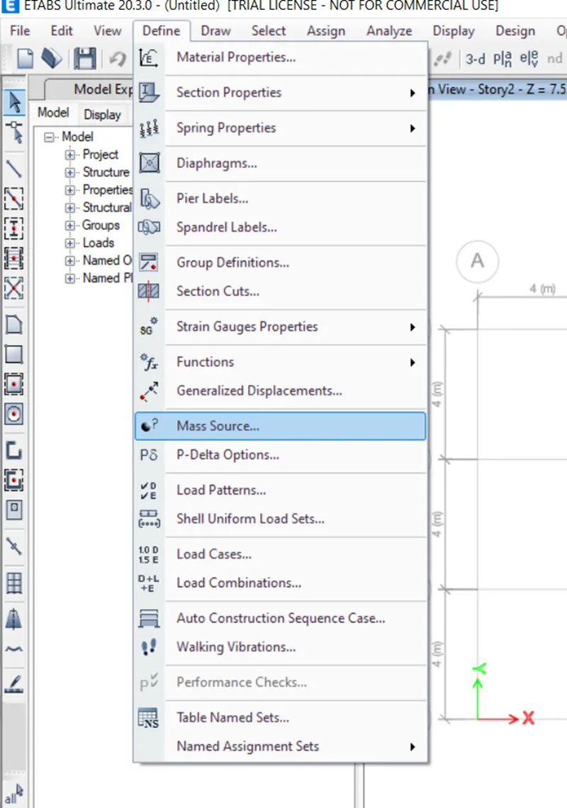
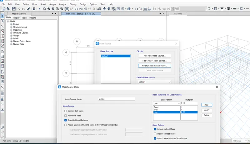
- defining mass source as shown below
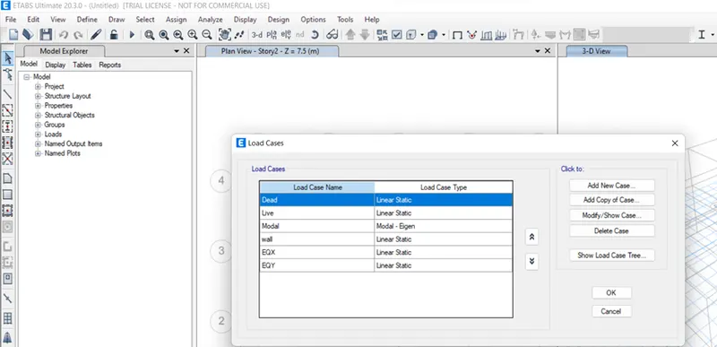
- checking load cases, whether the necessery loads are defined are not.
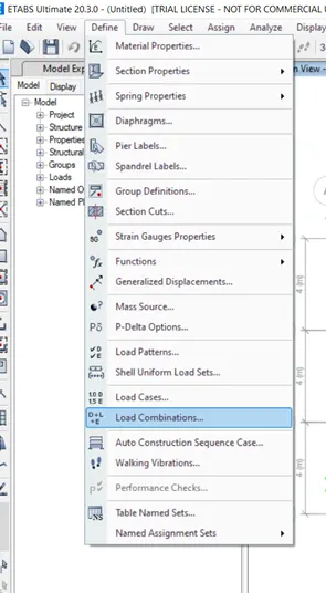
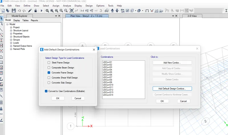
- defining load combinations as concrete frame design with convert to user combination and default design combos.
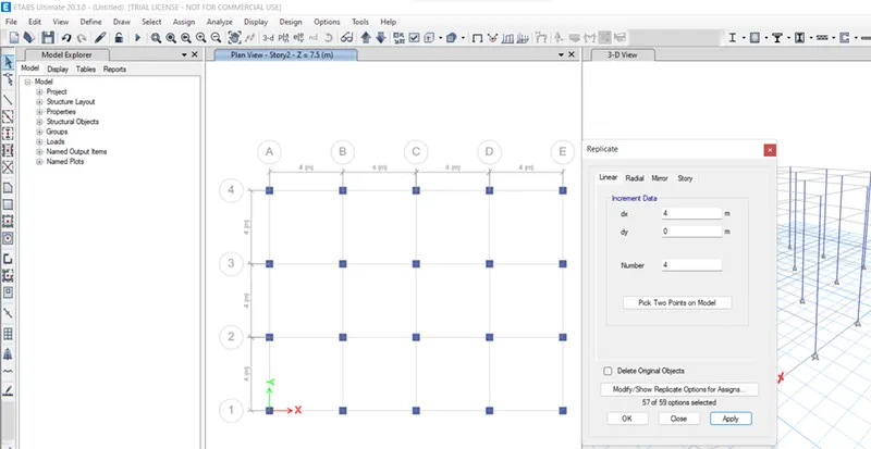
- now, i am gonna do modelling using quick draw column, quick draw beams and floors as shown below.
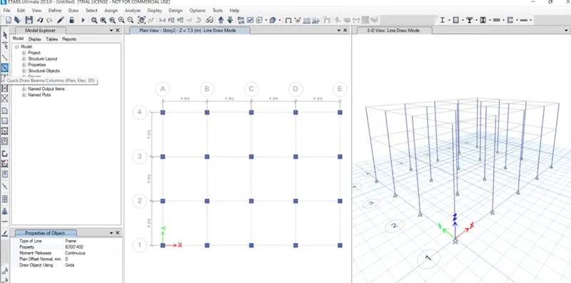
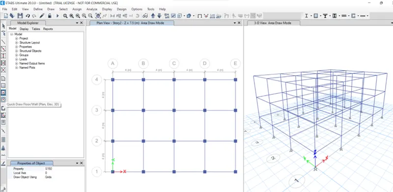
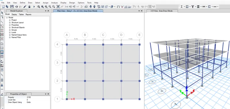
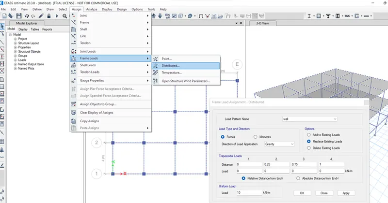
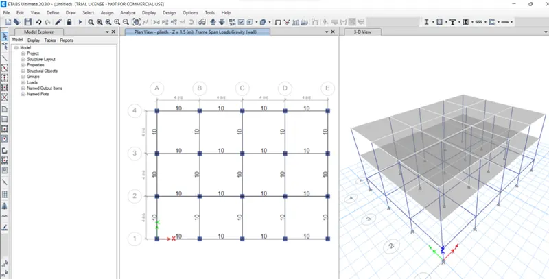
- now, i am gonna assign the loads such as wall load on beam section as 10kn/m and slab has the distributed load as 3kn/m as shown below.
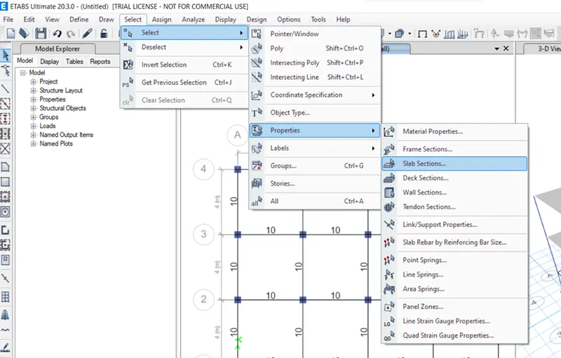
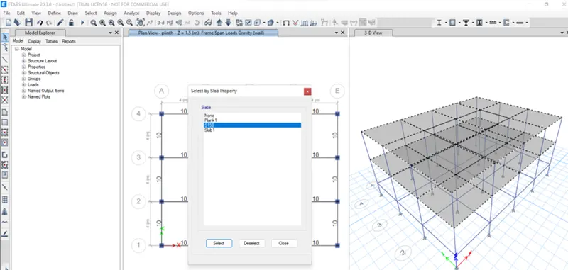
- for the assigning of loads, the sections should be selected first and then the loads are assigned as shown below.
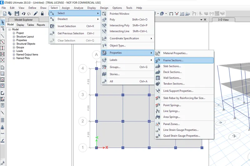
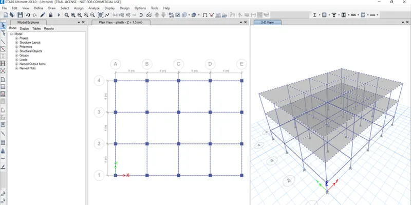
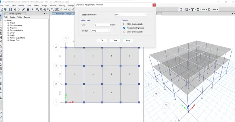
- assigning the diaphragm on slab
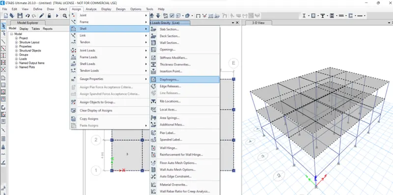
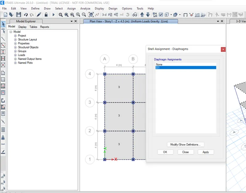
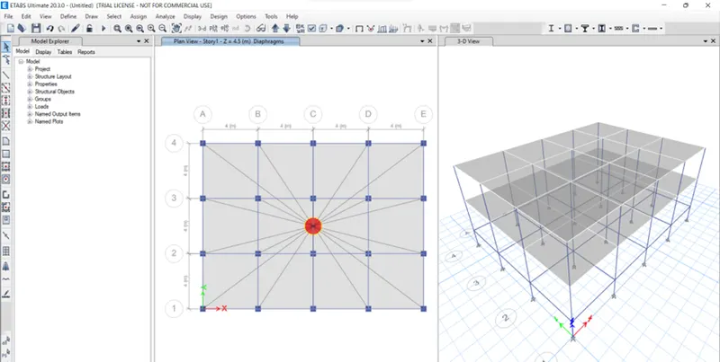
- saving the model as model-a and analyzing the model for results
- after that, making model-a to model-b by save as option.
- for model-b, the stories are 5 which gonna increased by using the option called edit stories and grid systems.
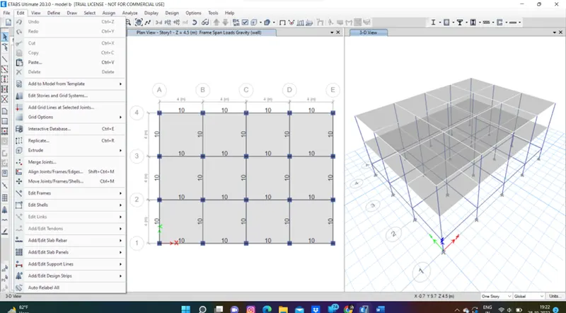
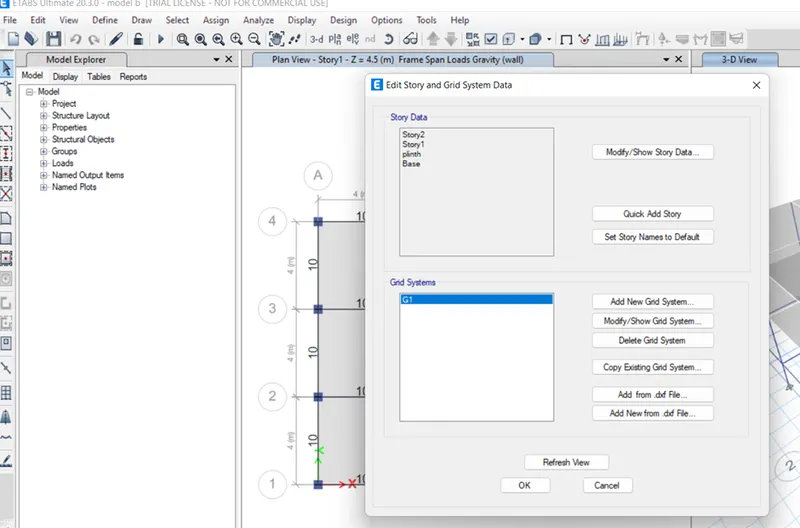
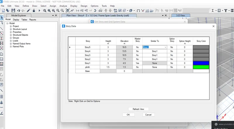
- checking the loads, after increasing the stories, whether the loads are automatically assigned or not.
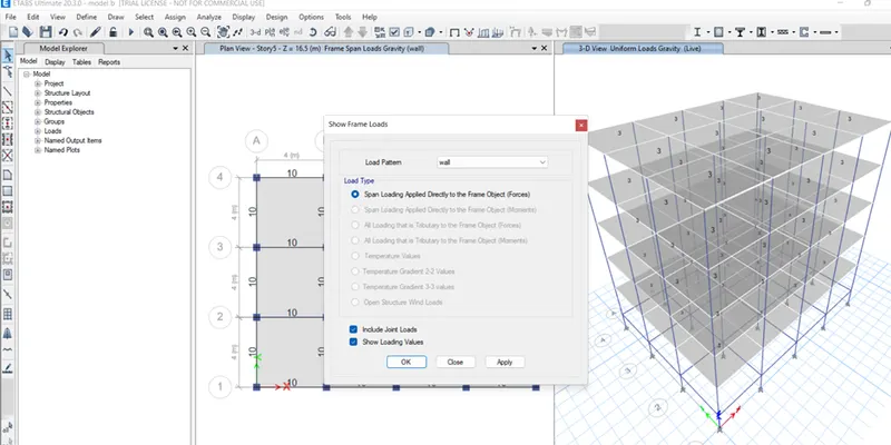
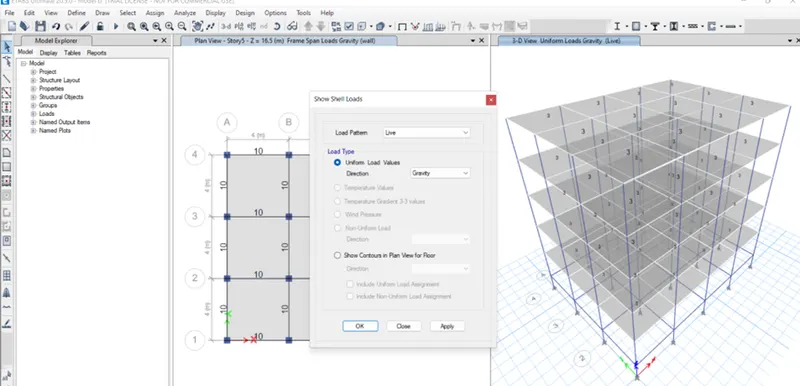
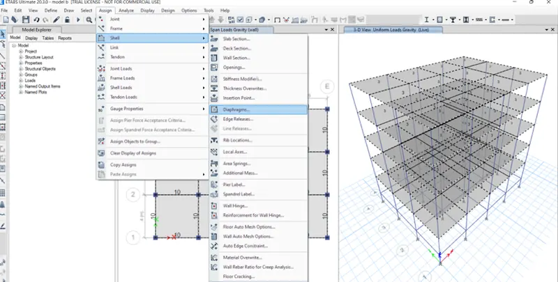
- assigning the diaphragm for the model as shown below
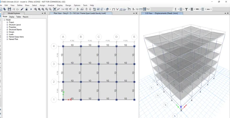
- after that, the model is analysed for results as shown below.
- afterthat, using save as option, i am gonna create the model-c from previous model
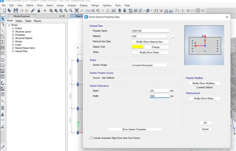
- model-c has the column size of 550mm*300mm, it is edited using the previous column details located at define->section properties->frame section->C400*400->modify properties ->the details are modified as per the model-c
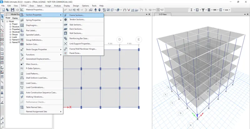
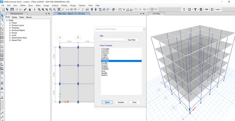
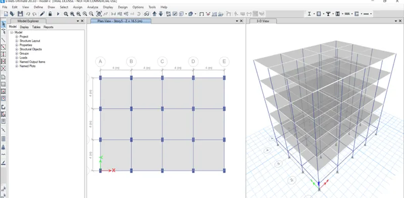
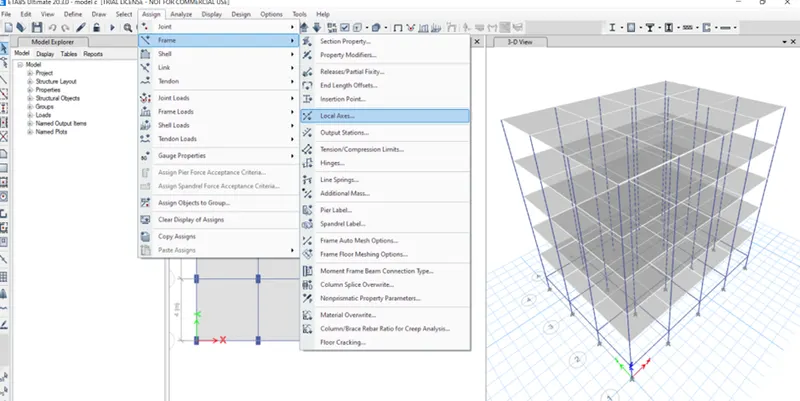
- the column is oriented along the x-axis is shown below,for that selecting the column, then using the option assign->local axis->angle should be provided 90 degrees->apply as shown below
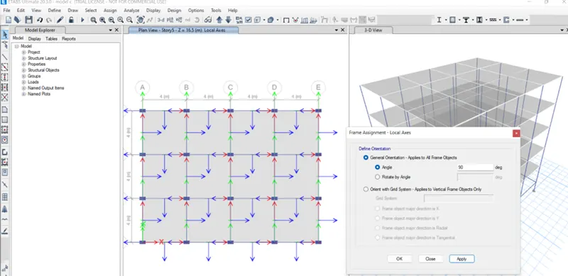
- the diaphragm is aslo provided and then analysed for the results.
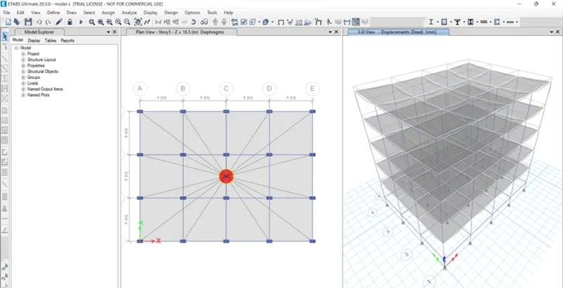
- again the model is save as model-d, in this, the column orientation is along y direction
- using the option called local axis, the angle should be 0 degrees, then the column should be as shown below
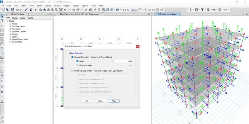
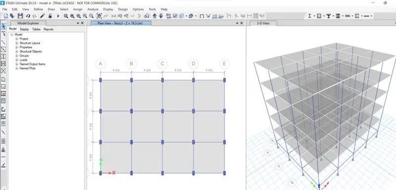
- the diaphragm is assigned and analysed for the results
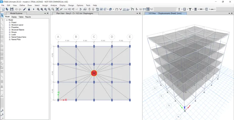
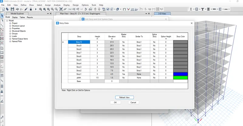
- again the model is save as model-e, for this model, the stories are edited to 10 stories and the two different column sizes are assigned which are 400*400 for upper 5 stories and 600*600 for bottom 5 stories as shown below
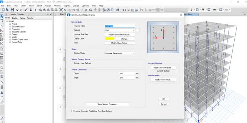
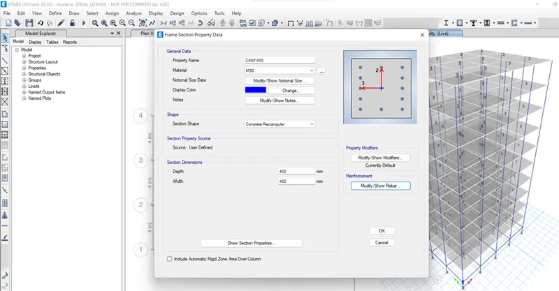
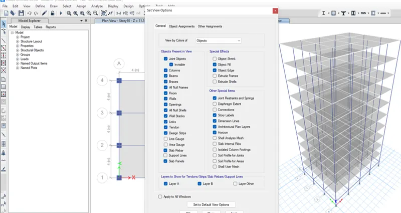
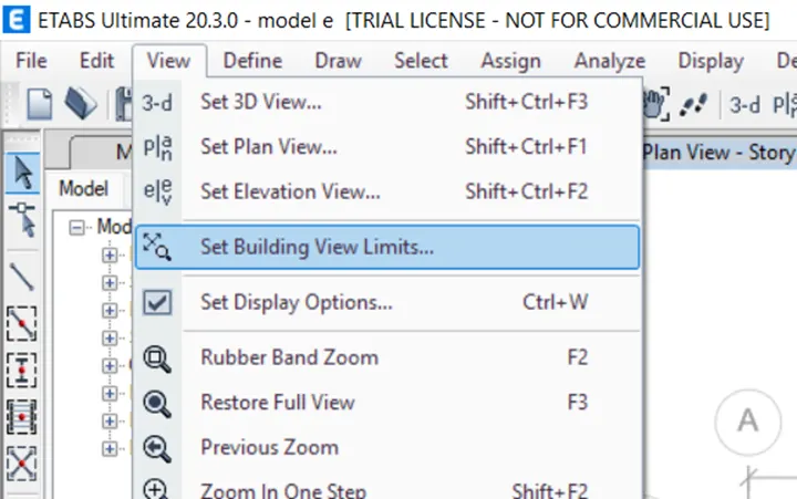
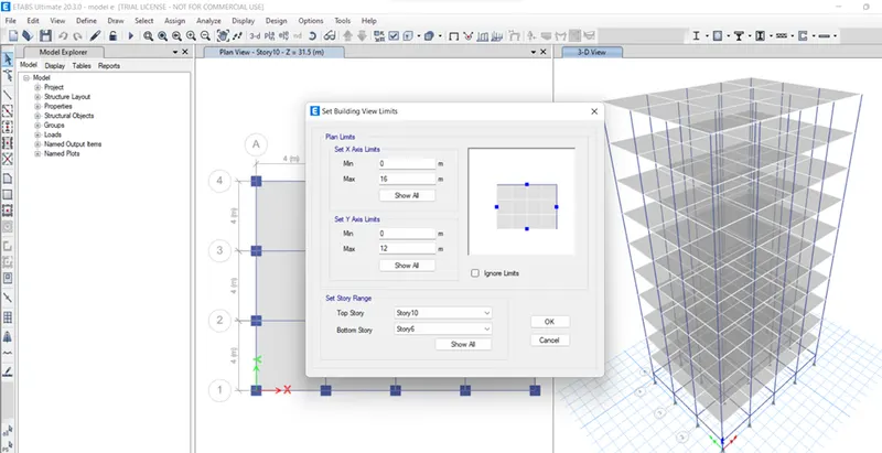

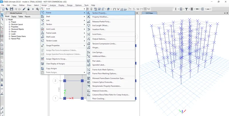
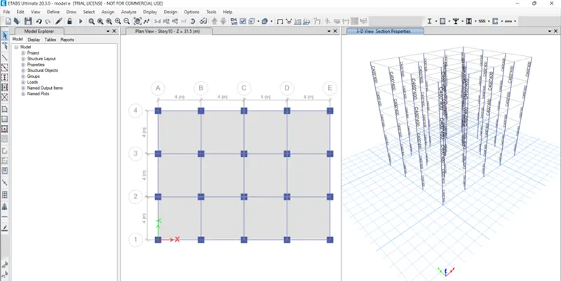
- diaphragm is assigned to the model and analysed for results as shown below
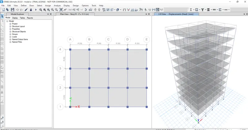
- again the model is save as model-f, it has the whole model column size is 600*600. it is obtained by editing the previous column and assigned it to the model as shown below.Diaphragm is also assigned and analysed for results
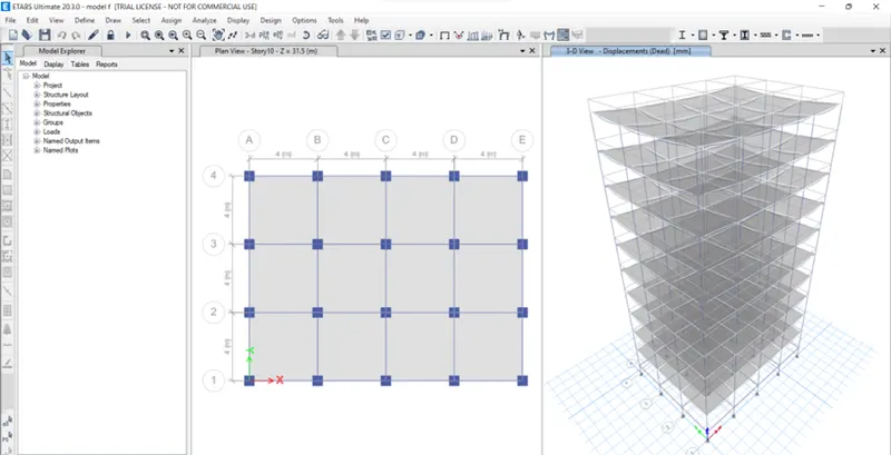
- again the model is save as model-g, it has the following variations

- the stories are edited using the option edit story and grid system and the three different columns are defined and assigned to respected levels given in question
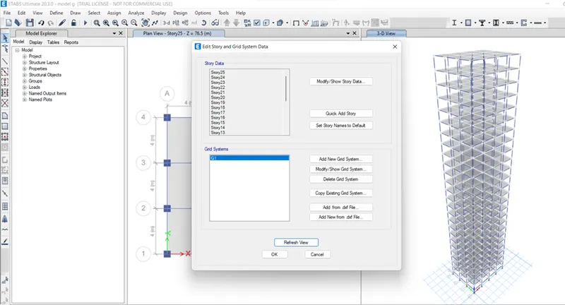
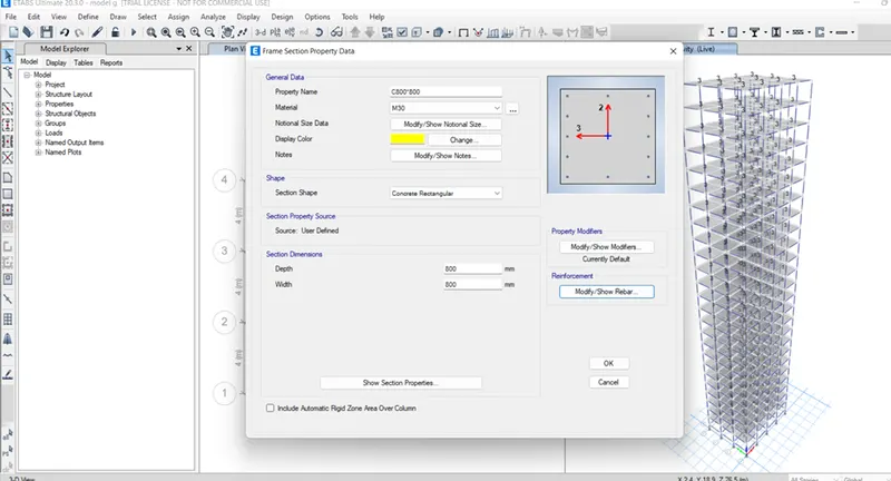
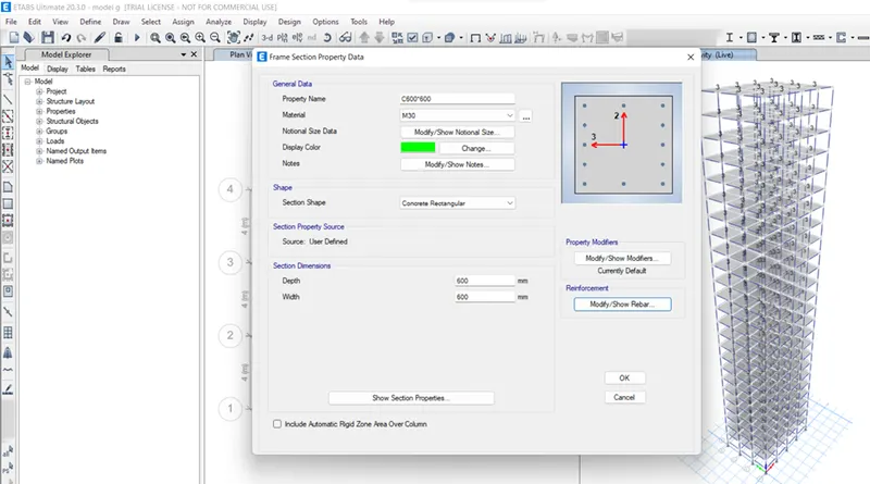
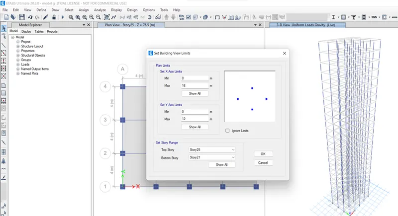
- the column variations are shown clearly below
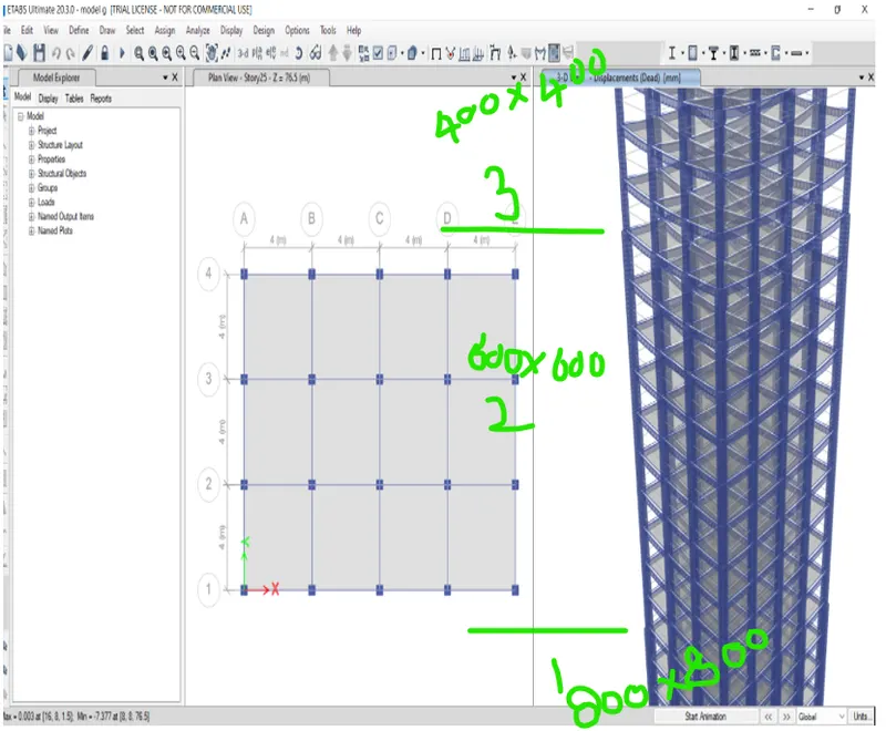
- diaphragm is assigned and analysed for the results
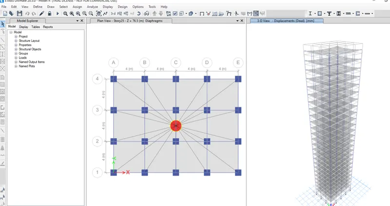
- again the model is save as model-h, it has variation in column is shown below

- the same size column is assigned through out the model
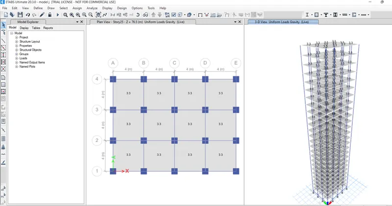
- the diaphragm is assigned and analysed for the results
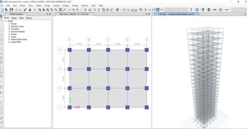
- again the model is save as model-j, it has the following variations

- the load variation is 10% higher than previous models is edited using the previous loads, and is applied shown below
- diaphragm is applied and analysed for results
- again the model is save as model-k, it has the variation in load is shown below

- here, again there is 10% increase in load, which is same as model-j. diaphragm is also assigned and analysed for results
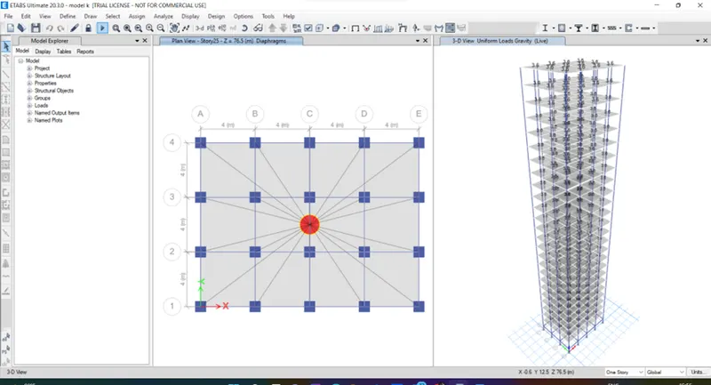
- the entire modelling is completed, then we will see the results and comparisions in result.
RESULT:
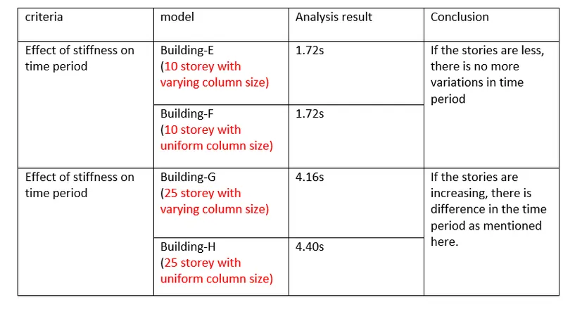
- effect of stiffness on time period:
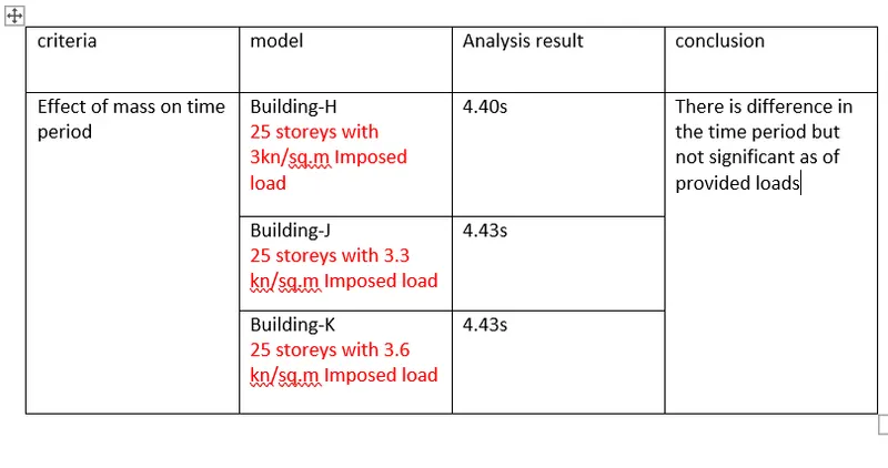
- effect of mass on time period:
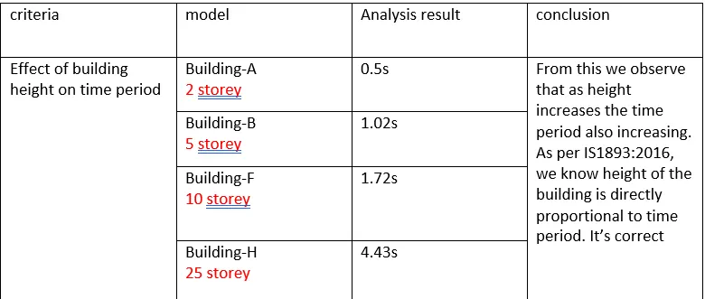
- effect of building height on time period:
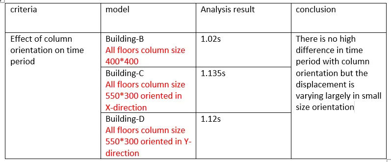
- effect of column orientation on time period
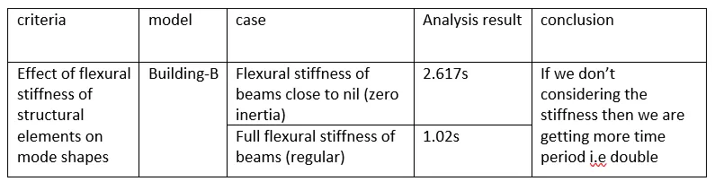
- effect of flexural stiffness of structural elements on mode shapes:
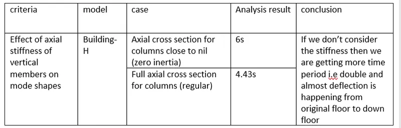
- effect of axial stiffness of vertical members on mode shapes:
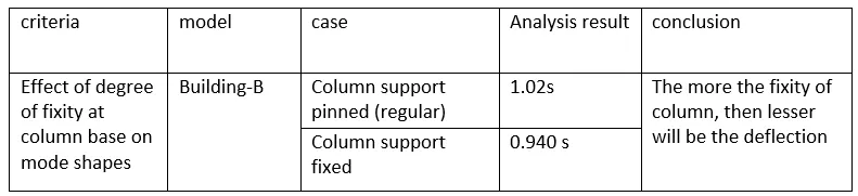
- effect of degree of fixity at column base on mode shapes: