Project 1_Comparative study of different storey buildings for Seismic forces
Aim:To model 10 different buildings and compare them with respects to mode shape,natural periods.
software that i used -ETABS
Step by step procedure
MODEL A
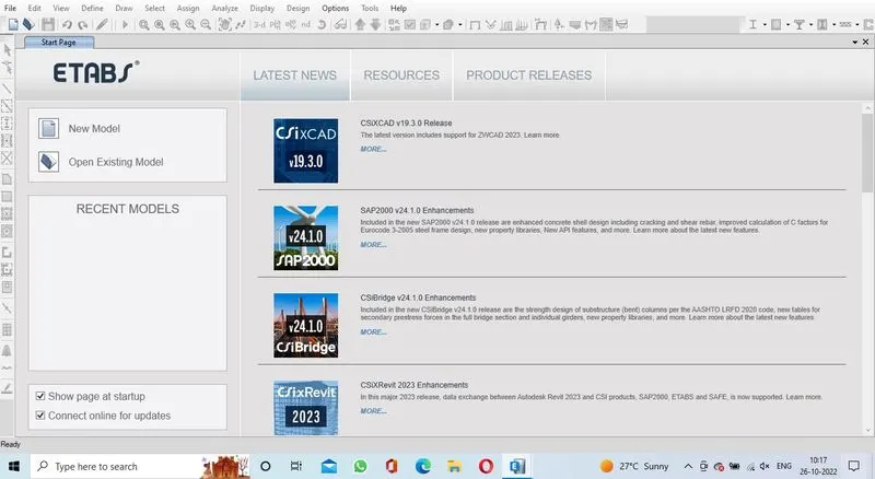
open ETAB software
click the new model in the interface page.
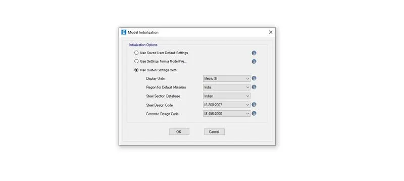
model initialization palette will open in that we need set the settings like this
- display units-metric IS
- region for default material- india
- steel section database-indian
- steel design code-IS 800-2007
- concrete design code-Is 456-2000
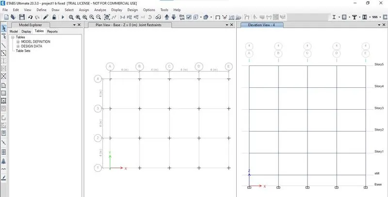
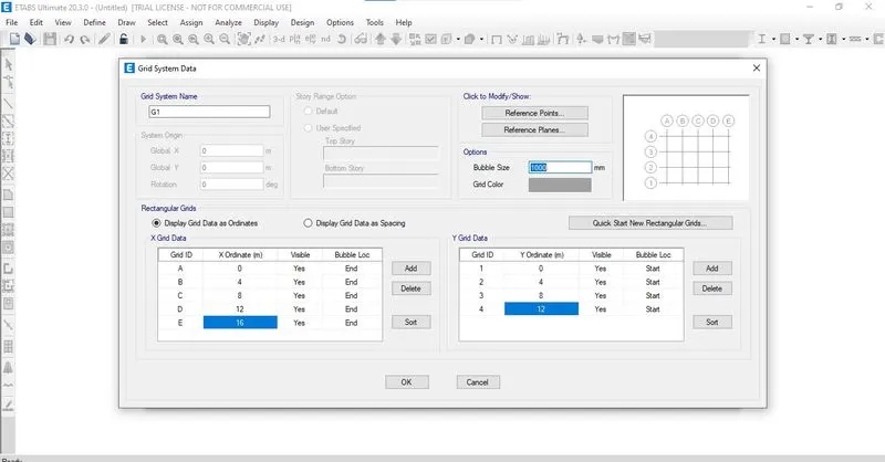
set the grid system data
provide 5 grid line along x -direction with spacing 4000mm.
provide 4 grid line along y-direction with spacing 4000mm.
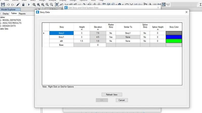
now set the storey data
first model having G+2
set the second storey similar to first storey.
go to define tab
select material properties and click new material property.
select the material as concrete.
set the necessary data.
add another material rebar.
set the necessary data.
again go to define tab---section property-- frame section----add new property.
select the rectangular concrete.
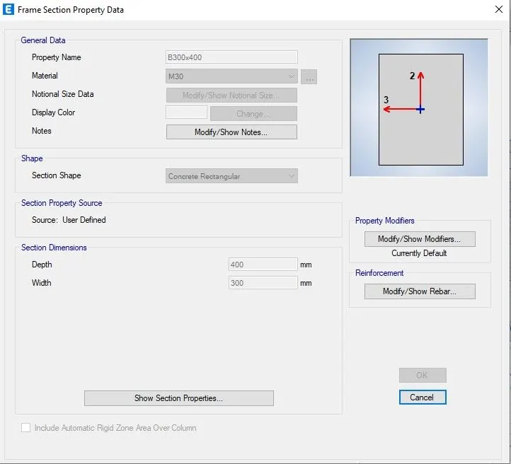
rename the property name -B300x400.
change the dimension
- depth-400
- width-300
when the load combination with seismic
we need change the property as per standard.
for example moment of interia for beam-0.35
present no need to change the properties.
go to reinforcement modifer
set the design type a beam
rebar details
- longitudinal bar-Fe415
- shear reinforcement-Fe415.
provide the cover 55mm.
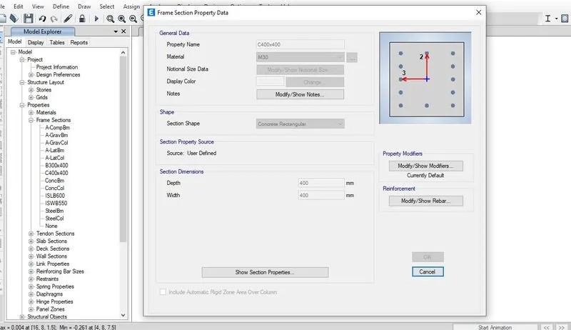
same procedure is repeated for column section
name it as C400x400
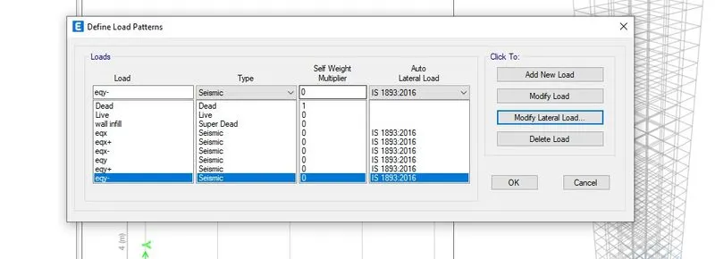
go to load patterns
set the load like this
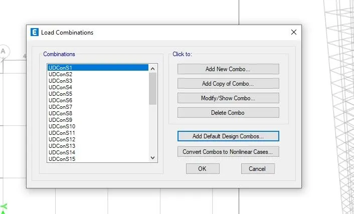
go to load combination
click default design combos
select the design type for combination-frame concrete design combo
enable the editing option.
go to mass source
click the modify
specify the load patterns like this
- dead load-1
- live load-0.25
- wall infill super dead-1.
go to slab section
add new
rename it as slab 150
set the type as membrane
set the thickness as -150.
now it time for modelling
take quick draw column tool.
select the all grid points.
set the section property as c400x400.
assign to all stories.
the columns are placed at the grids.
take quick draw beam tool
select all grid lines.
set the section property as B300x 400
set it for all stories.
the beams are placed on the grid lines.
take quick draw floor tool.
select the geomentry.
assign it to similar stories.
set the section property as slab 150.
placed between the grids.
select all beam .
frame load----uniform load.
assign wall infill super dead load -10 kn/m.
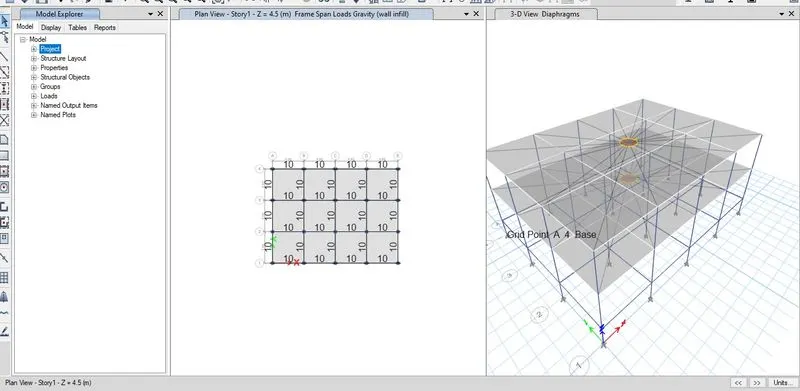
select all floor in all stories.
go to shell load----uniform load
assign live load 3 kn/m2
select the slabs in all stories
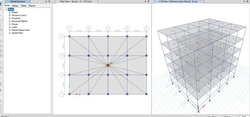
assign the diaphragms
check all loads are assigned (or) not.
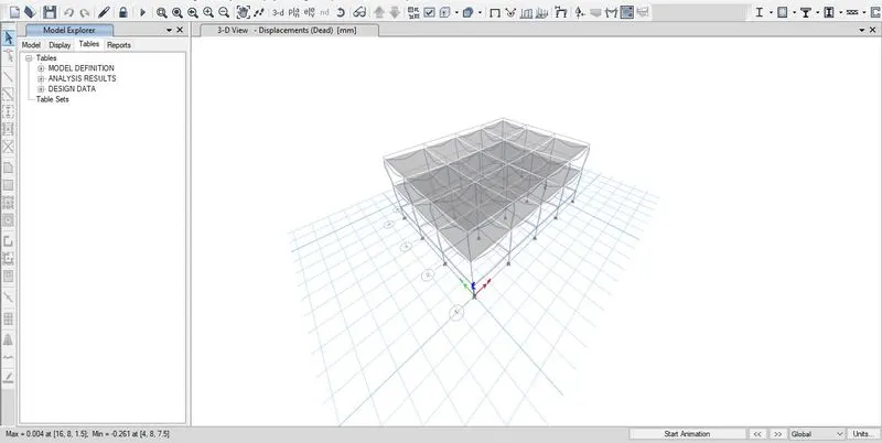
run analysis.
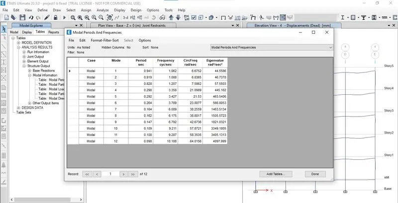
take the result of model time periods and frequencies.
MODEL B
save as the model A as Model B.
go to edit tab.
select the modify grids and stories.
right click on the 3storey and add 3 stories above it with same height.
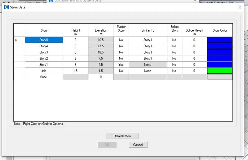
no need to change the model .
check all loads are assigned (or) not.
run analysis.
take the output results of model time periods and frequencies.
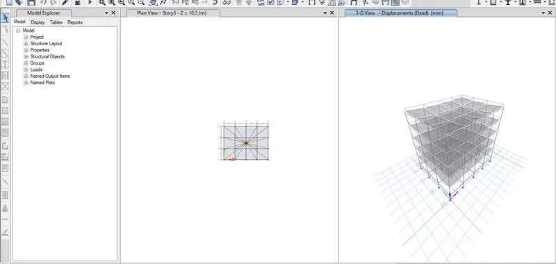
Model C
save as the model B as model C.
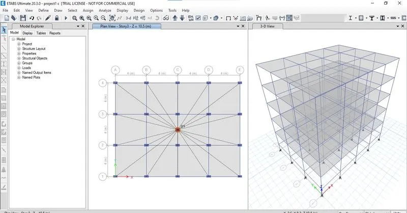
go to model explorer.
right click C400x400 section property .
click on modify.
set it as C 500x 300.
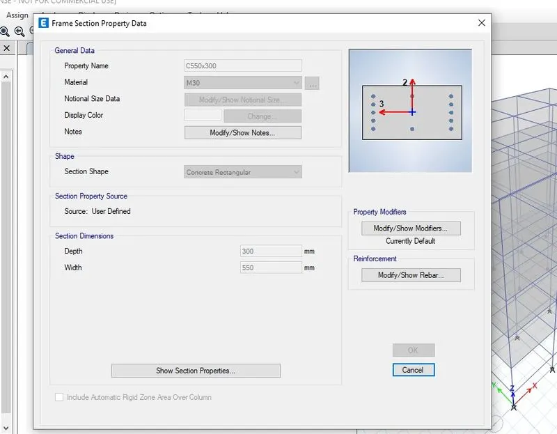
depth-300
width-500.
select all columns.
go to assign tab.
click on the frame section---local axes.
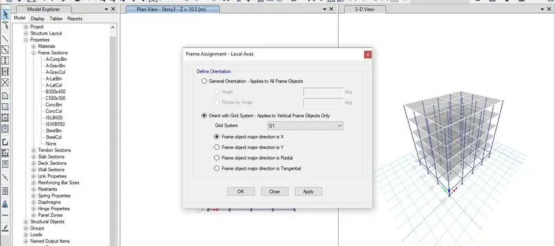
change the orientation angle -90 degree.(or) enable the orientation of vertical frames to major x-axis.
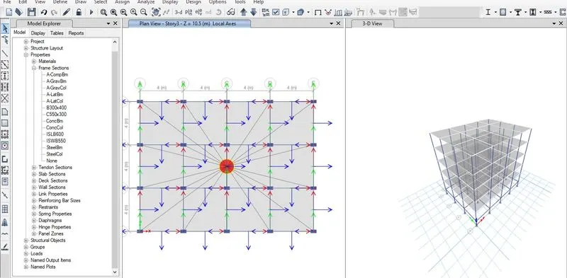
check all loads (or) not.
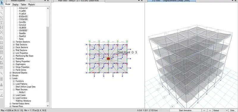
run analysis.
take output results of model time periods and frequencies.
MOdel D
save as model C as MODEL D.
select all columns.
go to assign tab.
click on the frame section---local axes.
change the orientation angle 0 degree.(or) enable the orientation of vertical frames to major y-axis.
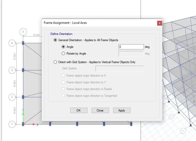
check all loads (or) not.
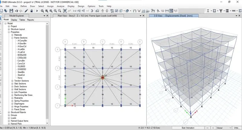
run analysis.
take output results of model time periods and frequencies.
ModelE
save as model D as model E.
go to edit tab.
click the modify grids and stories.
right click on the 5storey and add additional 5 stories above it with same height.
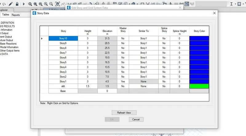
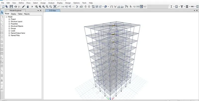
set the new stories similar to first storey.
hide all floors and beams.
go to section property add new property C 400x 400.
change previous column property and set it as C 600x 600.
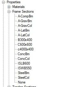
now all column sizes are 600x600.
select all columns
go to view tab.
set the building range.
upper storey-10
bottom storey-6
select all columns from strorey 10 to 6.
go to section property and set it as c400x400.
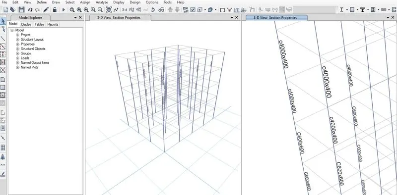
now all selected columns assigned the section property C400x400.
now unhide all floors ,beams and remaining columns.
check all loads assigned (or) not.
run analysis.
take output results of model time periods and frequencies.
MOdel F
save as model E as model F.
select all columns and assign property as C600x 600.
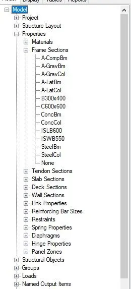
now all columns are in 600 x600.
go to model explorer.
select C400x400.
and delete it.
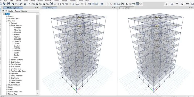
check all loads are assigned (or) not.
run analysis.
take output results of model time periods and frequencies.
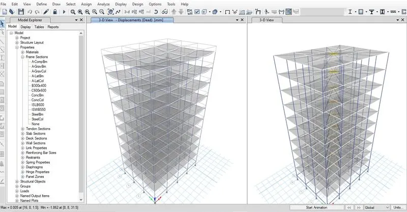
MOdel G
save as model F as model G.
go to edit tab.
click on edit grid and stories.
right click on the 10 storey and add 15 strories above it with same height.
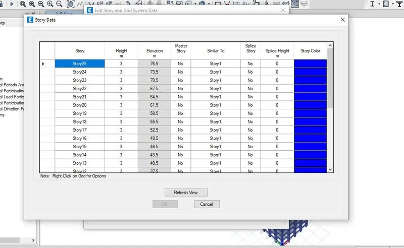
all added storey are similar to first strorey.
go to define tab---section property--frame section.
add new property.
c400x400
c800X800.
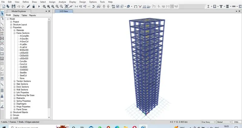
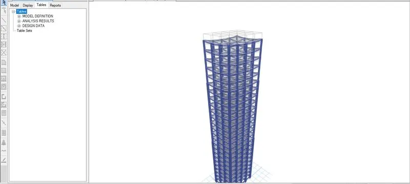
hide the all floors and beams.
select all columns.
go to view tab.
select the view range of building.
set the upper storey-25
bottom storey-21
select all columns and assign section property C400x400.
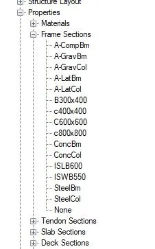
again view all.
set the view range of building.
upper storey-10
bottom storey-Base.
select all columns.
assign section property C800x800.
now unhide all sections.
check all loads are assigned (or) not.
run analysis.
take output results of model time periods and frequencies.
MOdel H
save as model G as model H.
select all columns and assign section property C800 x800.
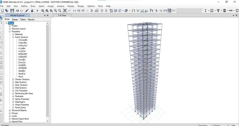
remaining columns are delete go on to model explorer.
check all loads are assigned (or) not.
run analysis.
take output results of model time periods and frequencies.
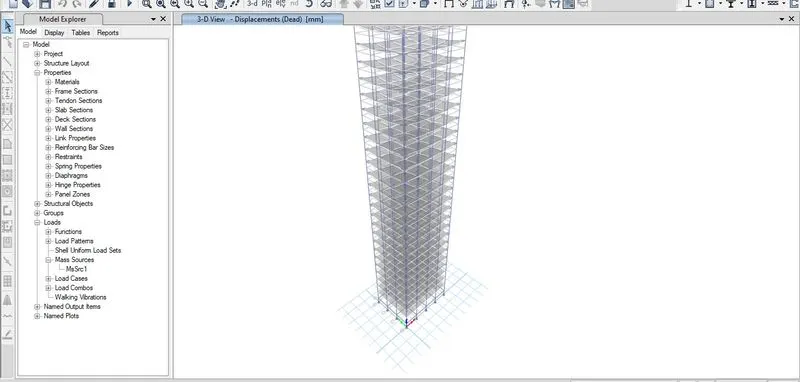
MOdel J
save as model Has model J.
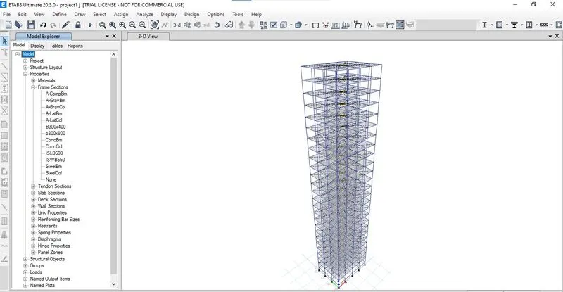
select all floors in all similar stories.
go to assign tab.
go to shell load.
select the uniform load.
set the live load as 3.3 Kn/m2.
add 10 %increament to previous load.
assign it to all floors.
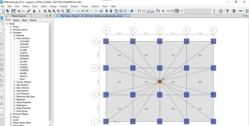
check wall infill assigned (or) not.
run analysis.
take output results of model time periods and frequencies.
MOdel K
save as model Jas model K.
select all floors in all similar stories.
go to assign tab.
go to shell load.
select the uniform load.
set the live load as 3.6 Kn/m2.
add 10 %increament to previous load.
assign it to all floors.
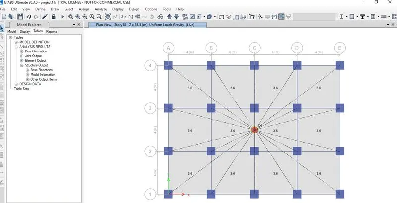
check wall infill assigned (or) not.
run analysis.
take output results of model time periods and frequencies.
Results I have completed modelling of 10 different buildings.
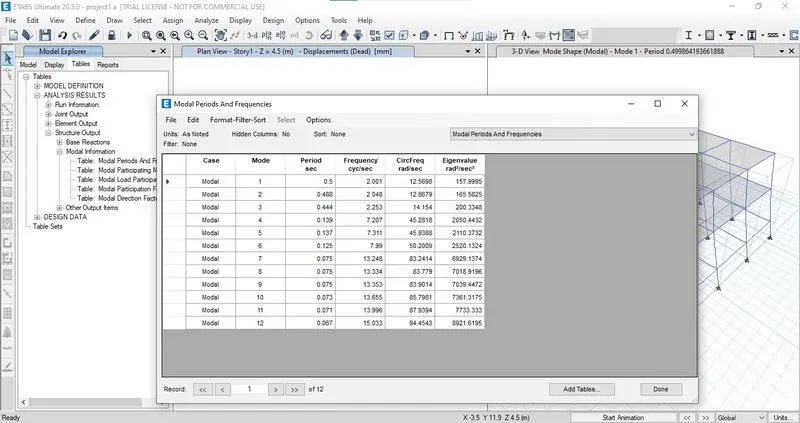
Model A
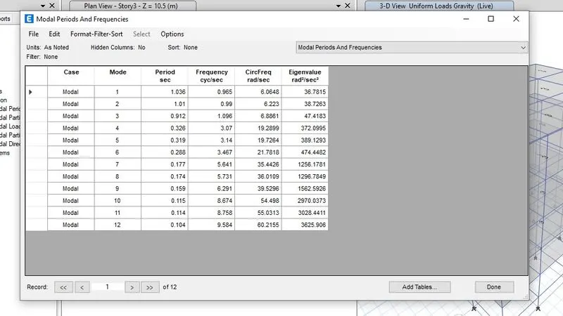
Model B
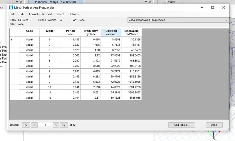
Model C
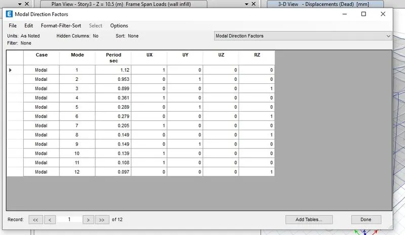
Model D
Model E
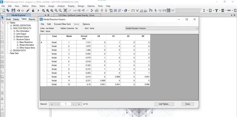
Model F
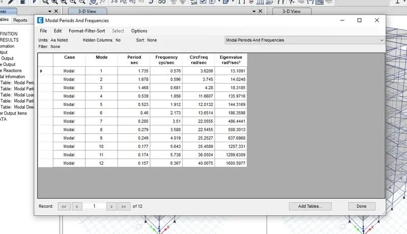
Model G
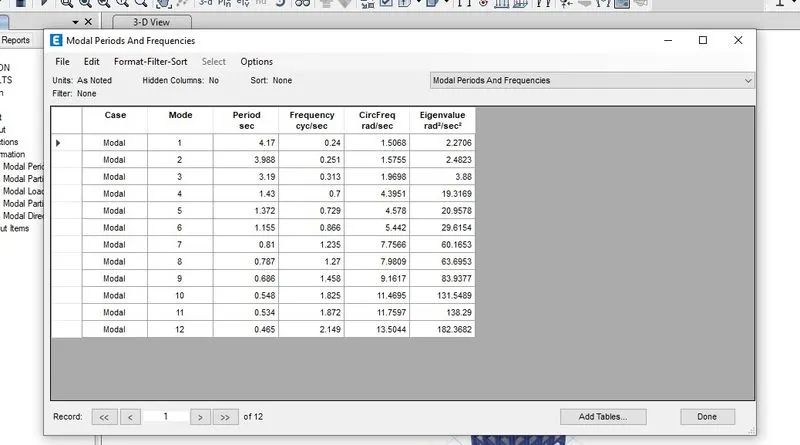
Model H
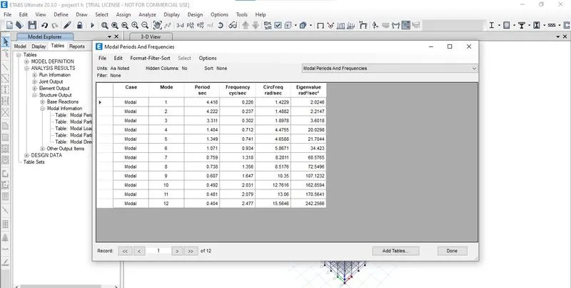
Model J
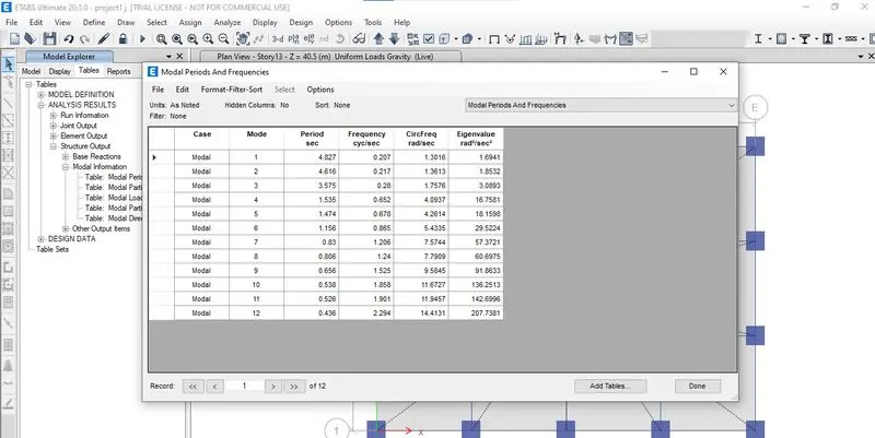
Model K
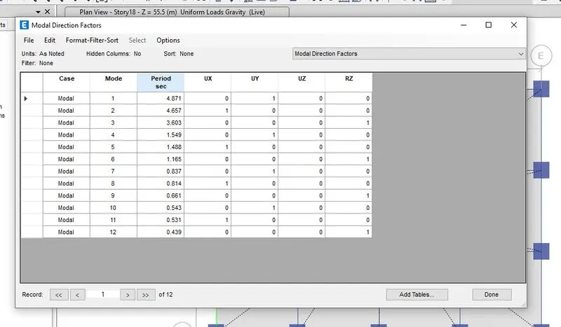
comparasion
Effects of stiffness on T
Model E-------Natural period-1.731sec
Model F ------natural period-1.735sec
Model G------natural period-4.17 sec
Model H-------natural period-4.41 sec
There is no significant change in E and F but slightly variation in the G and H because the moment resisting frame inter drift storey is most at the top .
Effects of mass on T
Model H-------Natural period-4.41 sec
Model J ------natural period- 4.82 sec
Model K------natural period-4.87 sec
mass is directly properional lateral load heavy interial forces acting on that diaphagrm so obivously natural period higher on that building.
Effects of building height on T
Model A-------Natural period-0.5 sec
Model B ------natural period-1.03 sec
Model F------natural period-1.735 sec
Model H-------natural period-4.41 sec
height is directional to natural period while increasing building height the natural period also increase.
Effects of column orientation on T
Model B ------natural period-1.03 sec
Model C------natural period-1.145 sec
Model D-------natural period-1.12 sec
when column is symmetrical natural peroid is low,in the C and D model the fundamental mode sightily significant mode are acting opposite direction.
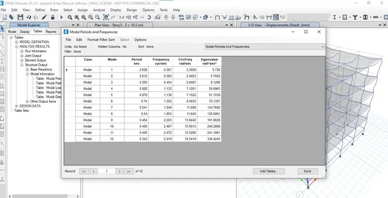
Effects of flexural stiffness of structural elements on mode shapes
MODEL B
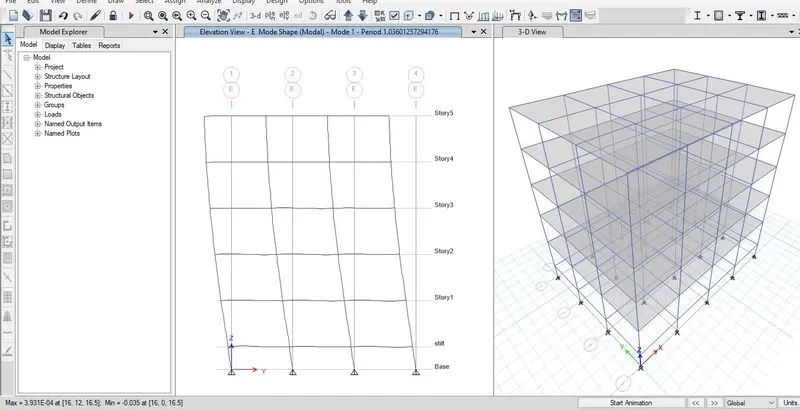
flexural stiffness less------natural period-2.62 sec
flexural stiffness is more----natural period-1.03 sec
when we change the moment of interia t low there is large deformation take place on the building so the natural period in the model B less stiffness is more.

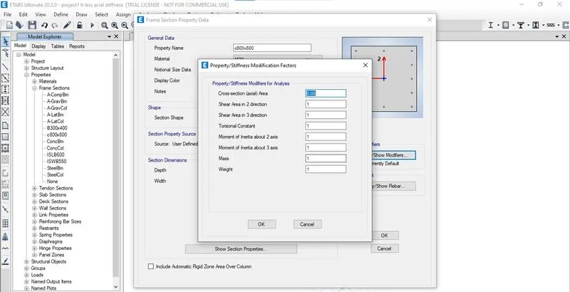
Effects of axial stiffness of vertical members on mode shapes
MODELH
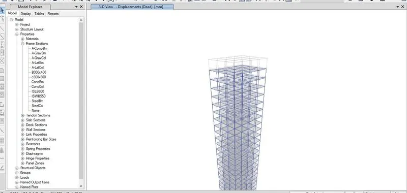
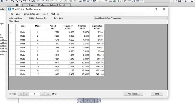
Axial stiffness is almost negleable---natural period-7.32 sec
Axial stiffness is full(regular)----natural period-4.41 sec
when we change the area of the cross section it directly effects the higher loads demand on the building so natural period in the first case is more.
Effects of degree of fixityof vertical members base on mode shapes
MODEL B
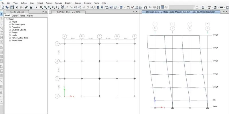
pinned----natural period-1.03 sec
fixed-----natural period-0.941 sec
when base is fixed it resist the inter storey draft at the base we can see it in the below.
se obviously natural period will reduce compare to pinned.