Project 1_Comparative study of different storey buildings for Seismic forces
Factors influencing the dynamic characteristics of a building
Factors influencing the Natural Period of a building
Factors influencing the Mode shape of oscillations
ANS:
AIM:
To have a comparative study on;
-
Factors influencing the dynamic characteristics of different storey building for seismic force
-
Factors influencing the Natural Period of different storey building for seismic force
-
Factors influencing the Mode shape of oscillations of different storey building for seismic force
INTRODUCTION:
- The structural configuration of the building plays a major role in determining the overall response during an earthquake. Different building geometries behave differently when induced by the same seismic forces. Hence, it is very important to properly understand the response of buildings related to their structural configurations for a safer design approach. Therefore in this project, we have modeled different buildings with varying geometries using ETABS. Furthermore, their responses are analyzed with the help of the software and the results are then compared to grasp an understanding of the structural behavior of buildings with different storeys.
- Every building offers a minimum resistance to the forces induced by the external effects like Earthquake. The important dynamic characteristics of a building are the modes of oscillation and damping.Thus it has effect of
- Flexural Stiffness of Structural Elements on mode shapes
- Axial Stiffness of Vertical Members on mode shapes
- Degree of Fixity at column bases on mode shape
GIVEN DATA:
- Structural Element Sizes :
- Beams : 300 × 400 mm
- Columns : 400 × 400 mm
- Slab : 150 mm thick
- Material Properties :
- Grade of Concrete : M30
- Grade of Steel Reinforcement Bars : Fe 415
- Loading:
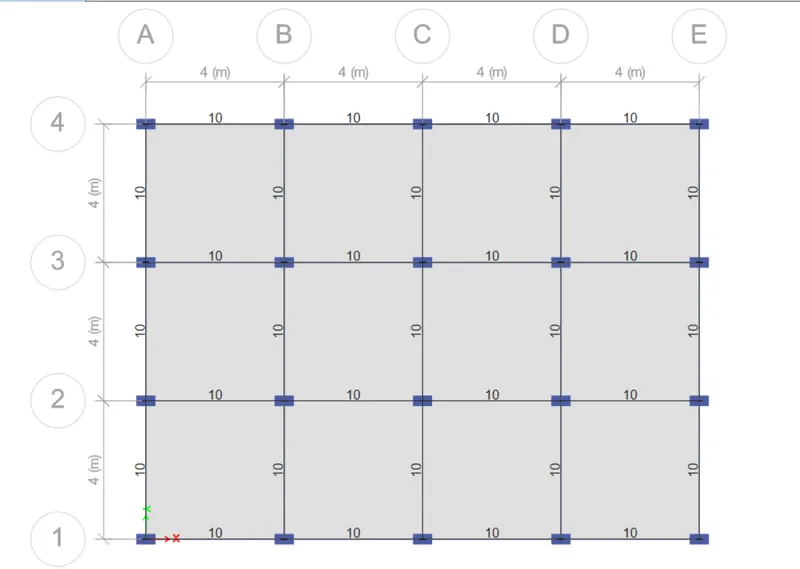
- Dead Load on beams from infill wall : 10 kN/m
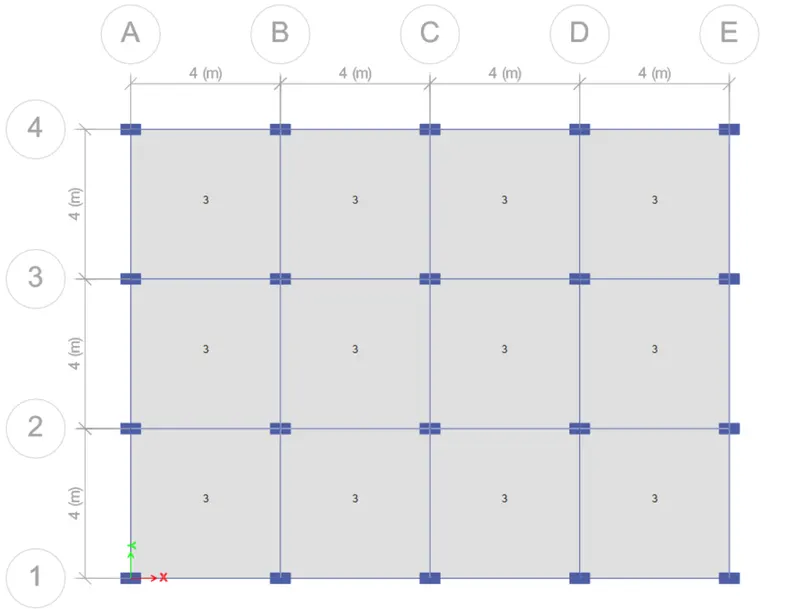
- Live load on floor : 3 kN/m2
- Buildings are assumed to be pinned at base
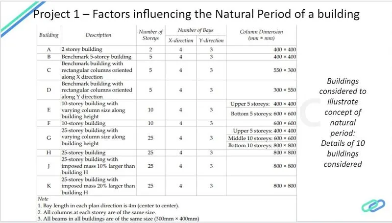
Buildings considered to illustrate concept of natural period
PROCEDURE:
1. BUILDING "A" (G+2):
- Open ETABS from the desktop shortcut or by searching for it from the start menu.
- Once the software is up and running, click on the new model option.
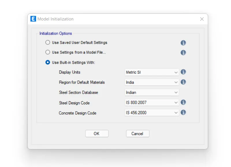
- Once you click on the new model, a dialogue box will pop up where you can set up the codes and units to be used in your project.
- Thus, do the needful settings and click ok to start modeling the first building in this project.
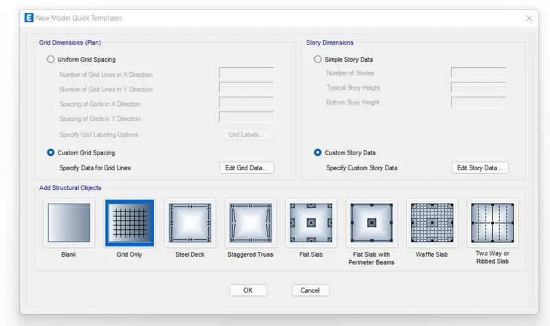
- To set up the grid data, you need to click on the custom grid option.
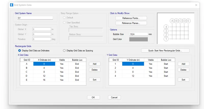
- Once you do that, a menu with all the grid settings will open up.
- In the same menu, you can fix the length, numbers of grids in both the orthogonal directions, spacing between all the vertical and horizontal grids, etc.
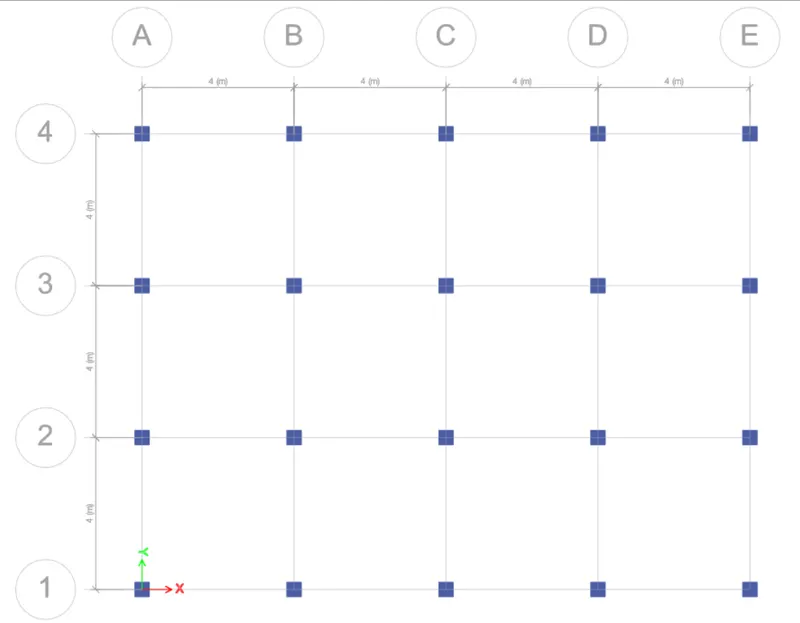
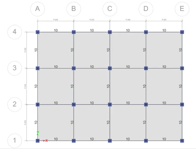
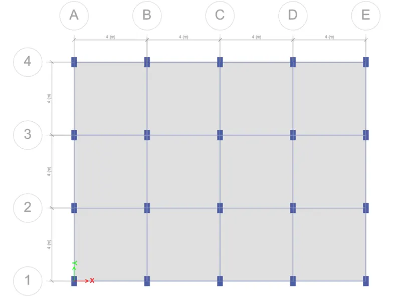
- So, by following the same approach, we have set up a 4 x 3 bay grid with 4m center to center spacing in-between.
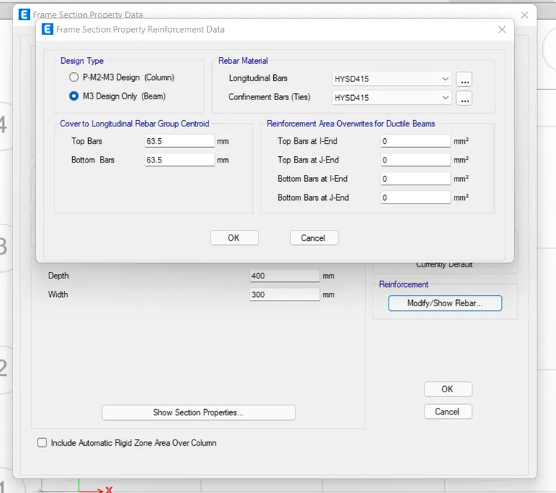
- Now select the Modify/Show rebar
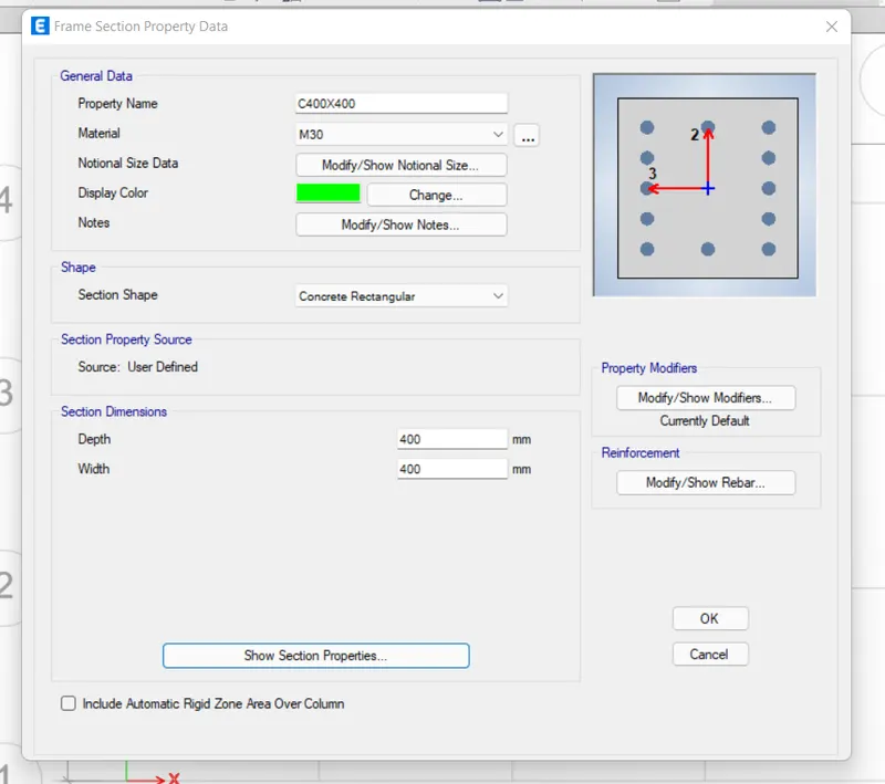
- Now to add the column property, select Define menu, select section properties, select Frame sections, Add new property
- Select Modify Rebar and edit
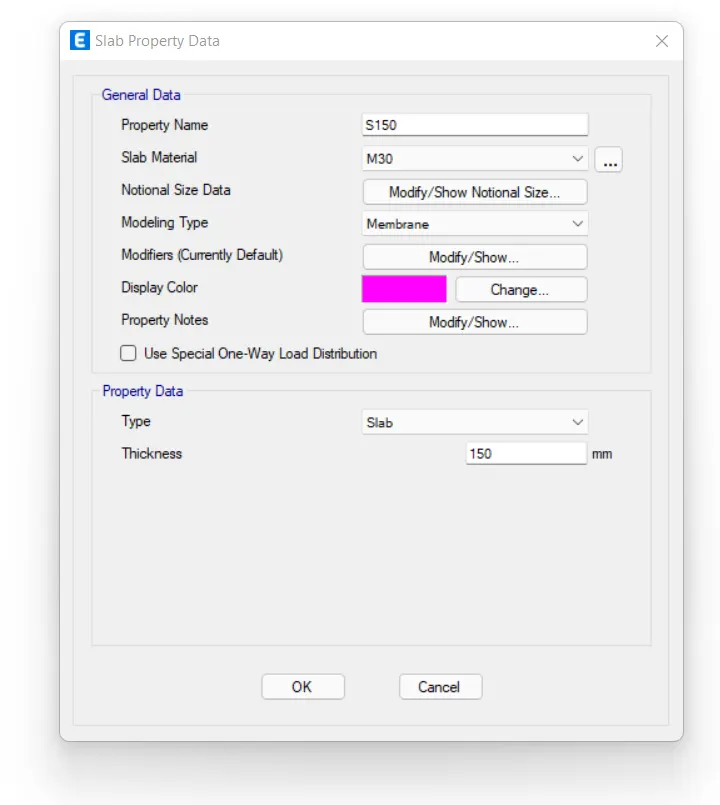
- Now to add the Slab property, again select the Define menu, Select Slab section and add new slab
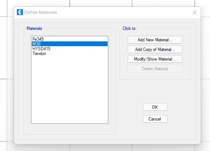
To similar to the C400x400
- Now using the Quick draw beams/columns option draw the beams and columns to the whole structure
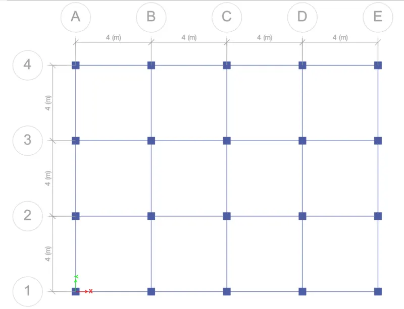
- Now we need to add the slabs Using Quick draw floor/wall option
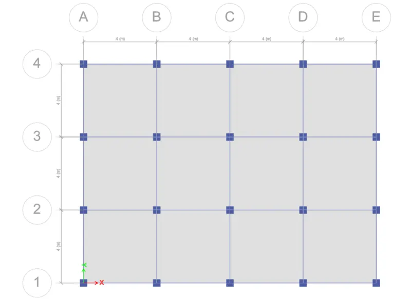
- After completing the model, now we need to list down the types of loads that are expected on the structure during its service period.
- And to do so, go to define>load patterns>add loads.
- Here, you can add all the loads and for our project, we are having the dead load, super dead load (Brick wall load), live load, and the earthquake load in x and y directions.
- Also, you need to define the mass source by adding 100% of dead and super dead load as well as 25% of the imposed or live load.
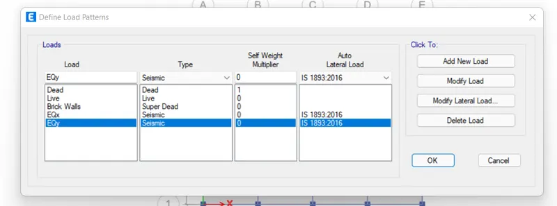
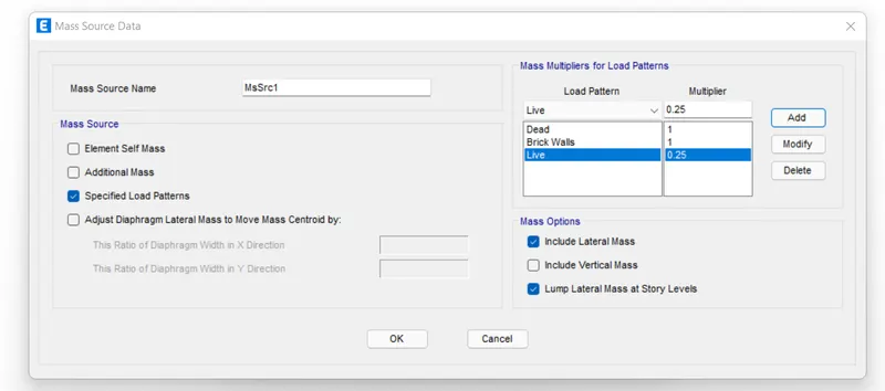
- You can select a particular structural member from the model and assign it the load that is imposed on it.
- For example, select the beam and assign a udl of super dead load due to the brick walls resting upon it.
- Thus, a similar technique is used and the loads on beams and slabs are assigned as follows:
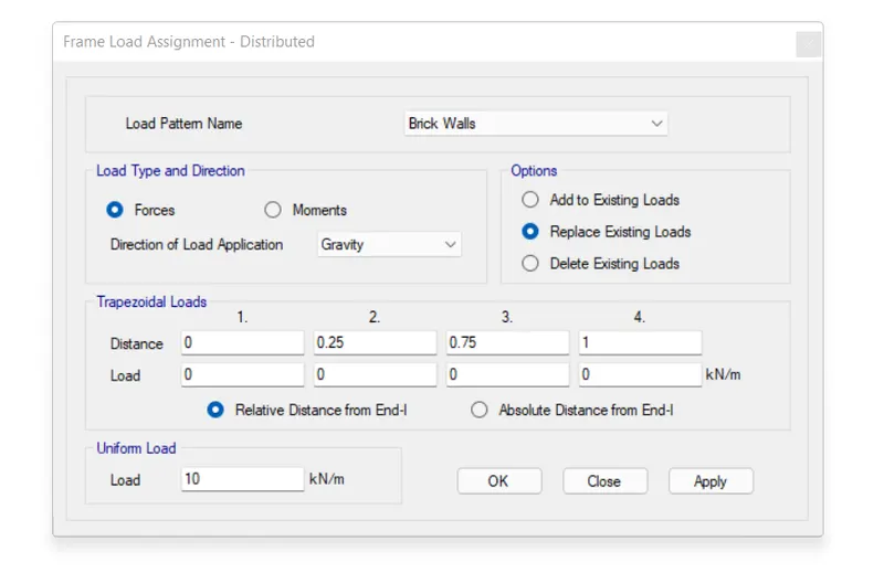
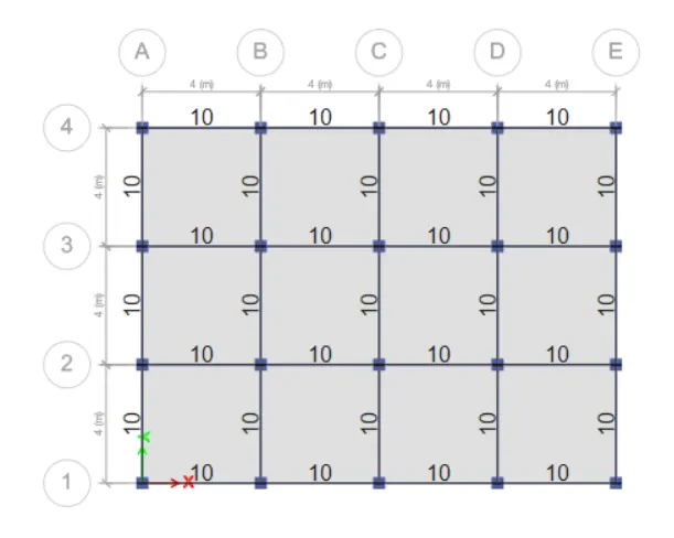
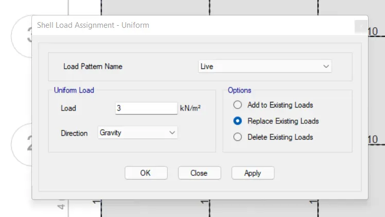
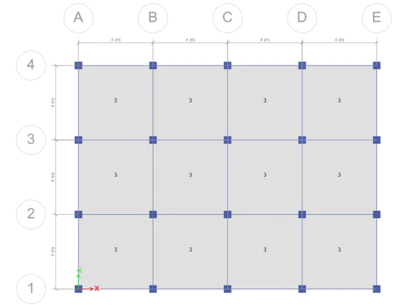
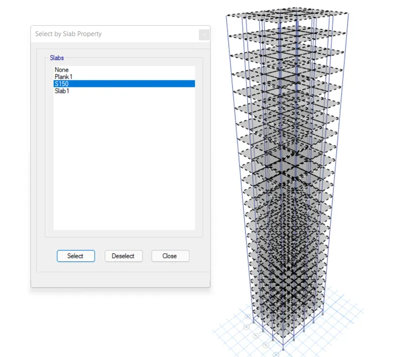
- Select the S150 slab section from the select option.
- Go to assign>shell>diaphragm.
- Select the default D1 diaphragm already incorporated in ETABS and press ok.
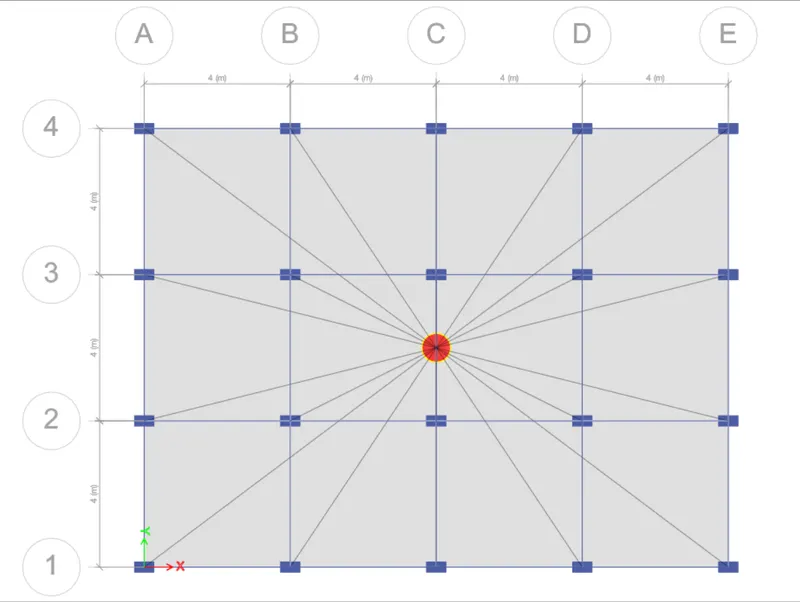
- It is now done, and you can see the center of mass for our model has been automatically calculated as we assigned the floor diaphragm.
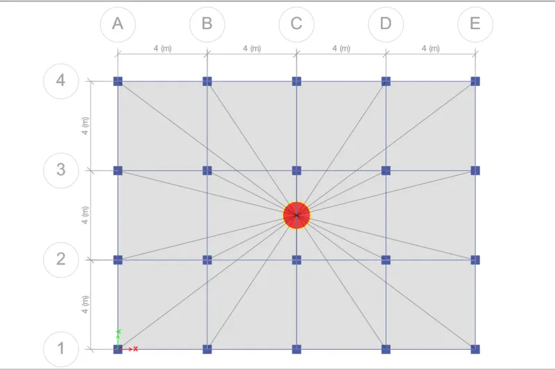
- Now that everything with regards to our first model is complete, we can proceed to run the analysis for this building.
- But we'll have to first save our project before running the analysis so do it at the preferred location within your system.
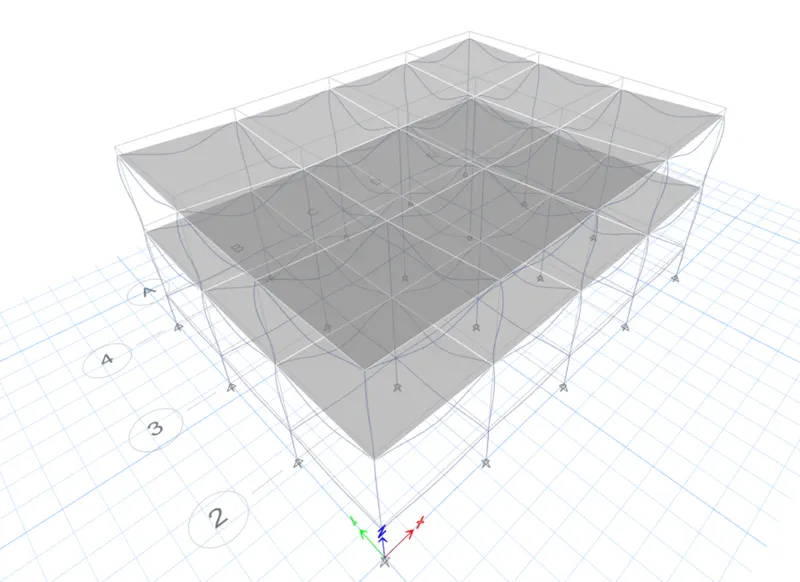
- Then, you can simply press F5 on your keyboard or click on the arrowhead available on the ETABS screen to run the analysis for the current model.
2. BUILDING "B" (G+5)
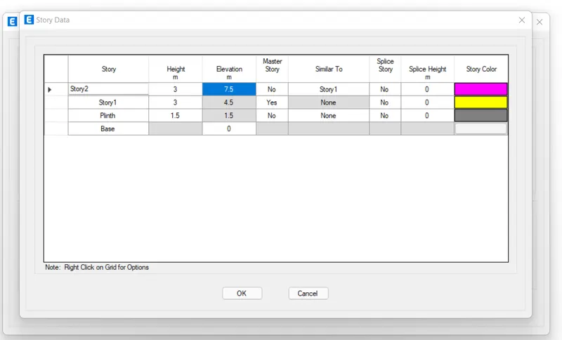
- Now to model building B, we need not create a new ETABS file from scratch. Rather we will save a copy of the building A file and do the alterations needed for building B. For example, we can increase the number of stories to 5 by editing the story data within the copied file. So, the complete procedure to do so in ETABS is discussed below
- From model A, go to files and click on the save as option.
- Set the destination folder and name it "BUILDING B".
- The model is set for changes as per the requirements of building b
- From the new file, go to edit>story and grid data.
- Click on the modify story data option.
- Then, right-click on the top story and select the add story option.
- Set the height and the number of storeys you want to add.
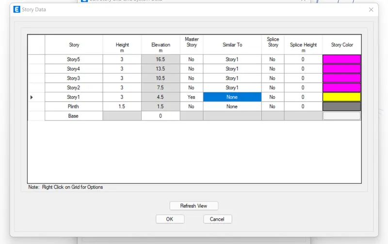
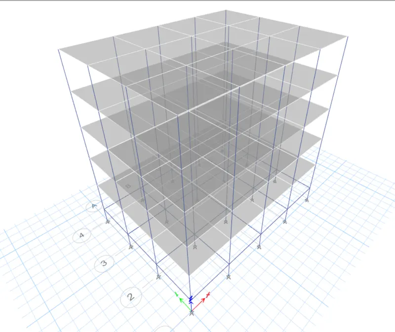
- In our case, we need to add 3 more floors to convert our 2 story building into a 5 story one.
- Also, make sure to make each story similar to the master story created in Model A.
- Now that our model is ready we need to check for two to three things before running the analysis and noting the modal period.
- The first check is for the load assignment.
- From the bottom ribbon in ETABS, go the show frame and shell loads one at a time.
- This way the model will show if the corresponding load has been assigned till the top floor.
- Similarly, you need to check if the diaphragm has been assigned to the new model or not.
- You can check it by going to the view settings option and checking the diaphragm visibility.
- If the diaphragm is not visible, you need to select all the floors and assign the diaphragm like we did for the first model.
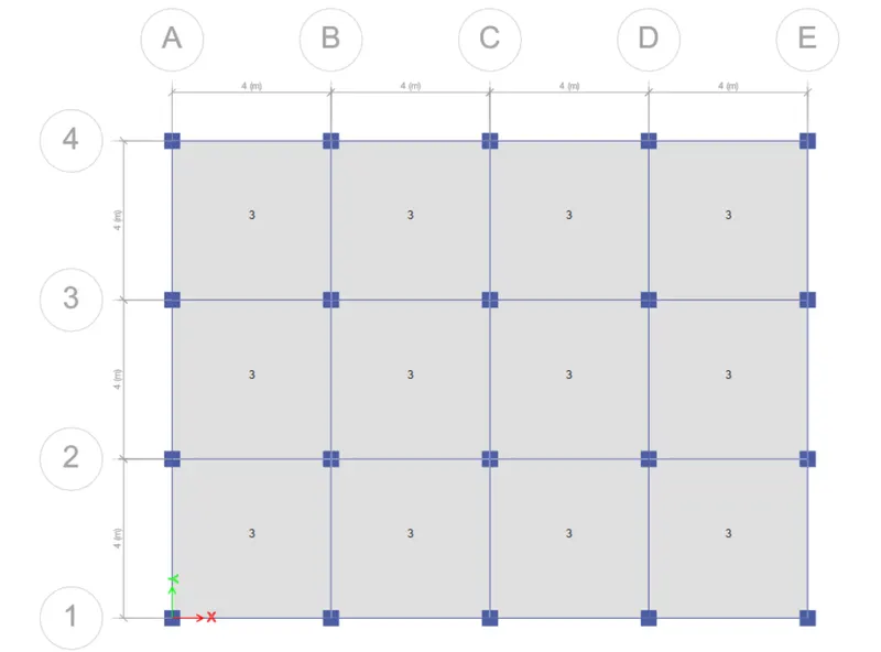
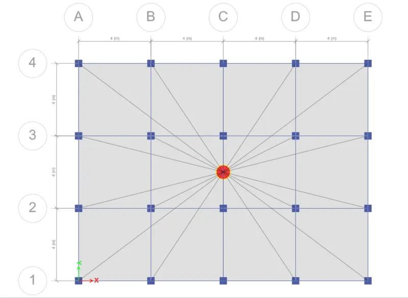
- Now that all the checks have been made and the structure is ok, we can run the analysis.
- And to do that simply press the F5 button on your keyboard or click on the arrowhead available at the bottom ribbon in ETABS.
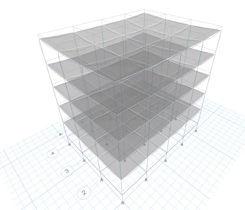
- It will take a few seconds and the deflected shape of the building will appear indicating that the analysis has been completed.
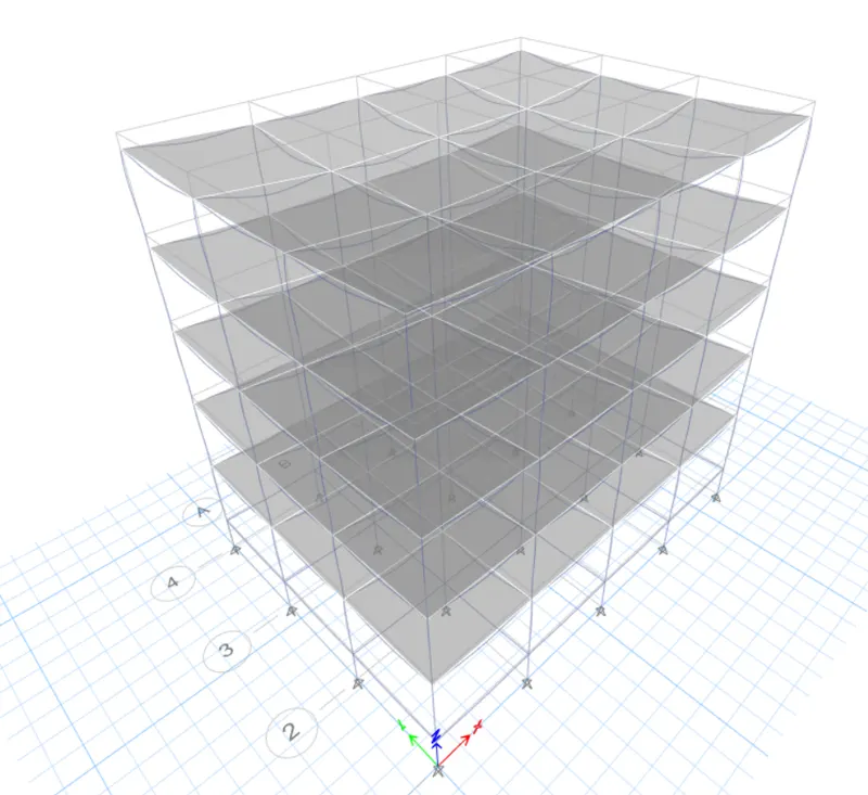
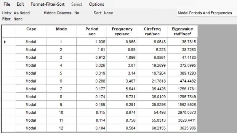
3. BUILDING "C" (G+5 with column orientation in X-direction)
- Like we did for building B, now do it for building C through building B.
- Choose the appropriate location and save the file as building c.
- Now, the model is set to be edited as need
- To edit the column section, go to define>section properties>frame section.
- Now, select the previously created column for building A and B.
- Click on the modify/show properties option.
- Rename the column as needed which in our case is 550x300.
- Then, edit the length and breadth by entering the values in the box.
- Now, we need to orient the 550mm in the X-direction.
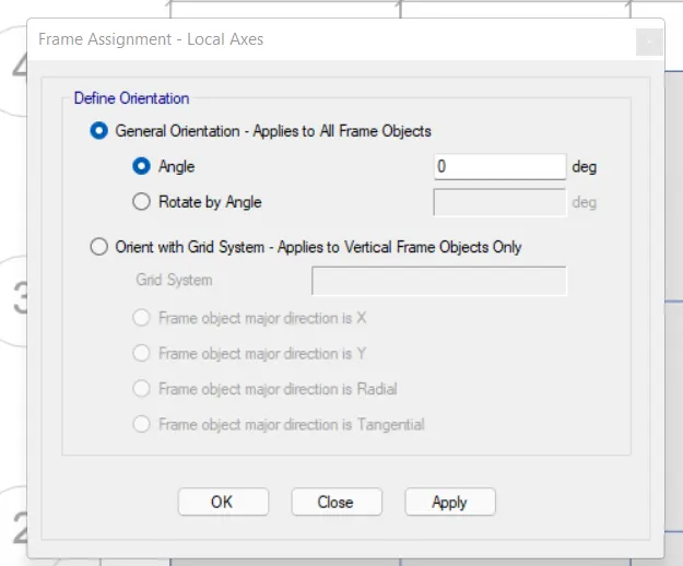
- So, select the column section then go to assign>local axis>rotate>90 degrees.
- This way, all the columns shall be oriented in the X-direction meaning 550mm laying down in the x direction.
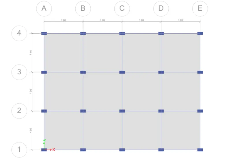
- Like we did for building B, checks for the frame and shell loads are to be made.
- Also, make sure the floor diaphragm has also been assigned before going ahead with the analysis.
- Go for an the run analysis tab check it
4. BUILDING "D" (G+5 WITH COLUMN ORIENTATION IN THE Y-DIRECTION):
- In this model, we don't need to alter anything other than the column orientation. The sizes of the column will remain the same however, we have to shift the column orientation from X to Y direction. So follow the same procedure as we did for the previous model and save as the C file into the D file.
- Then, select the column section and assign the local axes and bring the origin back to 0. This way, all the columns shall be oriented in the Y-direction. Then like usual, check for the loads and the diaphragm before running the analysis. Then, go ahead and note the modal period for building D.
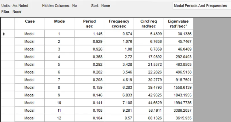
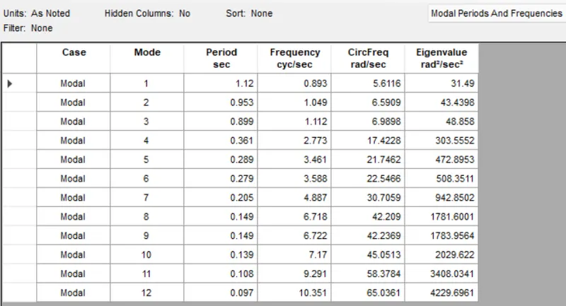
- So, as explained above, the model was executed for building D and the natural period was noted as inserted below
5. BUILDING "E" (G+10):
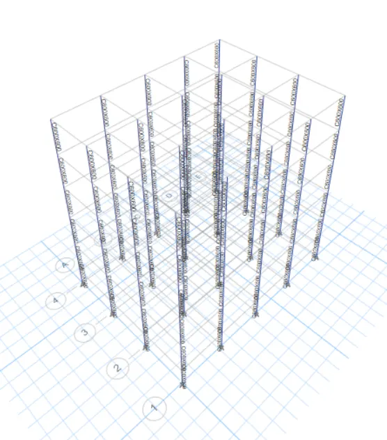
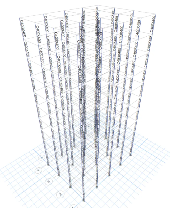
Column sizes for top 5 storeys: 400x400
Column sizes for bottom 5 storeys: 600x600
-
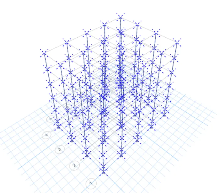
In this model, we need to add up 5 more storeys to our model. In addition, we also need to assign different column sizes on different floors. And to do that, we'll first save the ETABS file for building D as a new model for building E.
-
Then, edit the story data as we have done for our previous models in ETABS. Then, we need to add two new column sections with the required directions and assign them at appropriate floors in our model as specified.
-
The stepwise procedure to create new columns and locate them on required floors is explained below
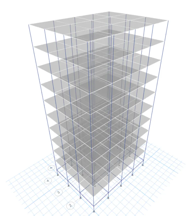
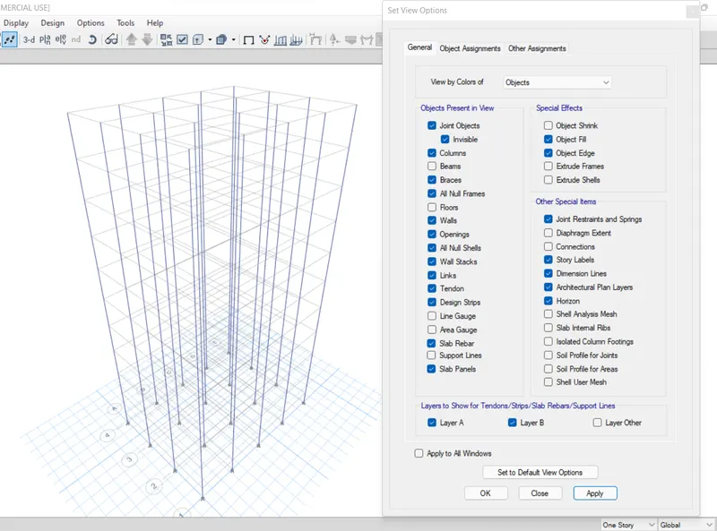
- There's an option in ETABS that allows users to adjust the model and view the only objects that are needed to be worked on currently.
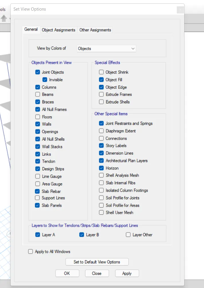
- The tool is called view option settings. It is easily accessible from the front tool ribbon of ETABS.
- So, you can go to view option settings and uncheck the structural members that you want to hide currently for modeling purposes.
- Since we need to assign different column sizes in our model, we don't need to view beams and slabs currently.
- So, we go to the tool and uncheck beams and floors in order to make the only columns visible for editing purposes.
- Now, since we need different columns for the top 5 floors and different columns for the bottom five.
- Therefore, we need to edit the top 5 and bottom 5 stories one after the other.
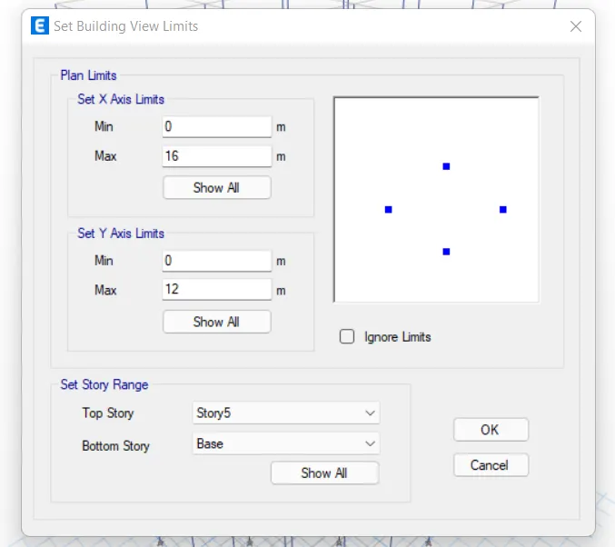
- So, we need first set the building limits up to the bottom five floors and then vice versa.
- And to do that, you can go to edit>set building limits.
- The set building limit option in ETABS allows you to view only the floors that you need to work on.
- Hence, first set the limit to bottom 5>select all columns by holding the left-click and making the box around the entire model>go to assign and assign them the required column section.
- Repeat the procedure for the remaining top columns and complete with the model.
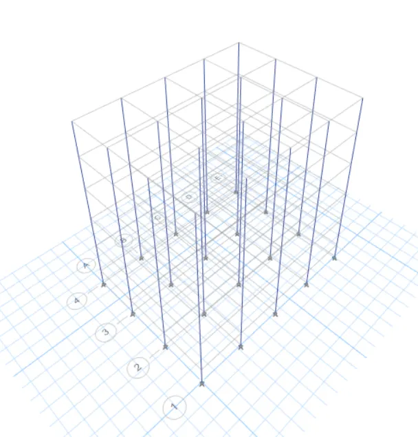
To add an material properties add column properties c400x400 and c600x600
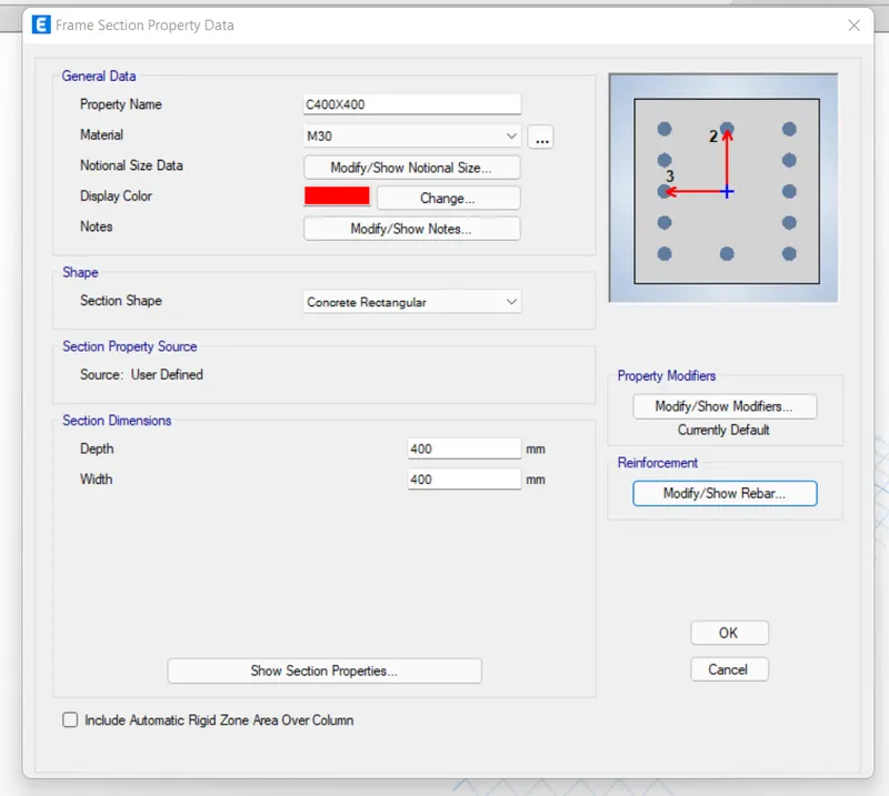
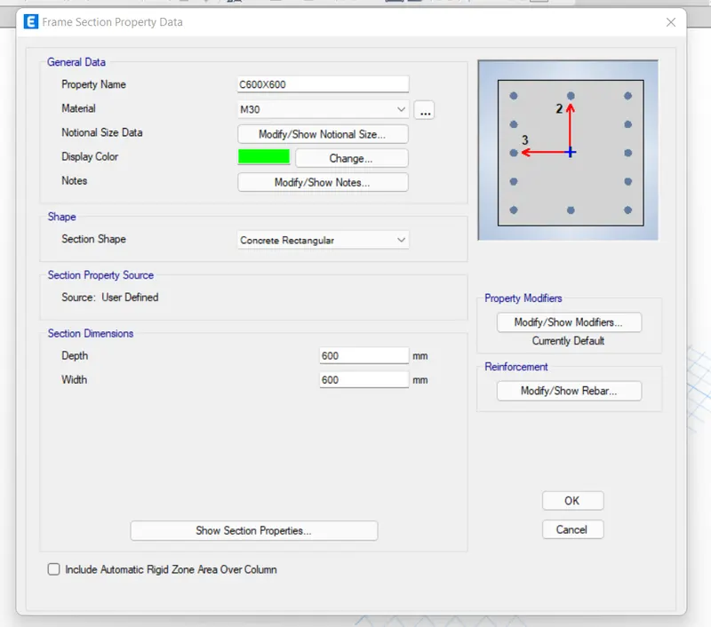
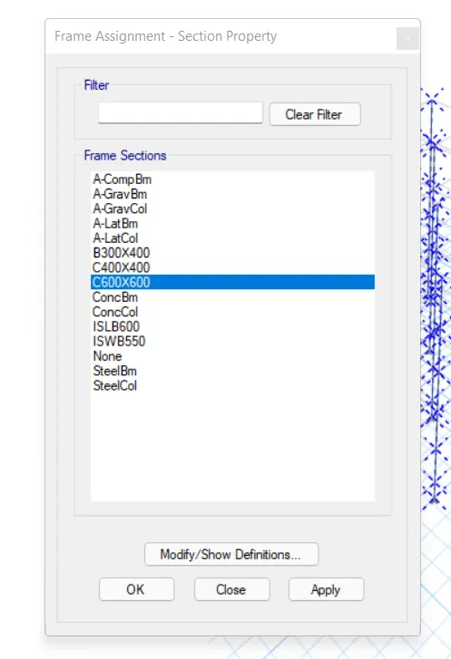
Same for an story 6 to story 10

6. BUILDING "F" (G+10)
PROCEDURE:
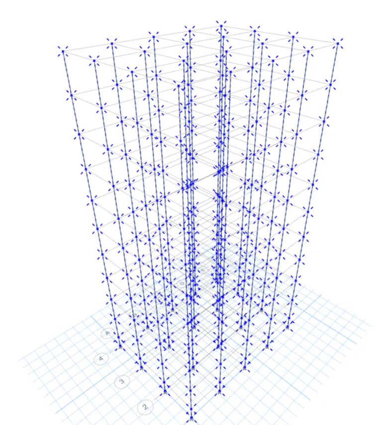
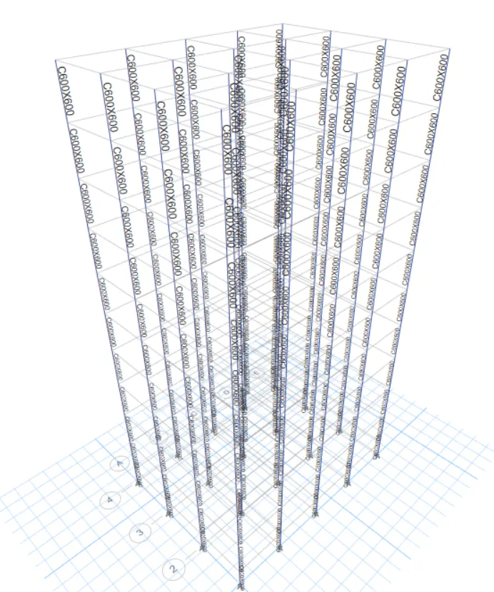
- This building has the same columns for the entire structure. Therefore, we don't need to do much editing in terms of the sections. We just need to adjust the view settings>hide beams and floors>select all the columns>assign them the frame section properties of C600x600.
7. BUILDING G (G+25)
Columns for top 5 stories: C400X400
Columns for middle 10 stories: C600x600
Columns for bottom 10 stories: C800x800
PROCEDURE:
- For this model, we need to add 15 new stories and assign different column sizes on different floors. We can follow the exact procedure that has already been explained for the previous project to create this model by editing building F. The same is discussed below:
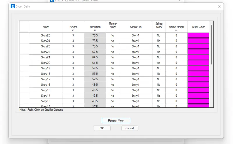
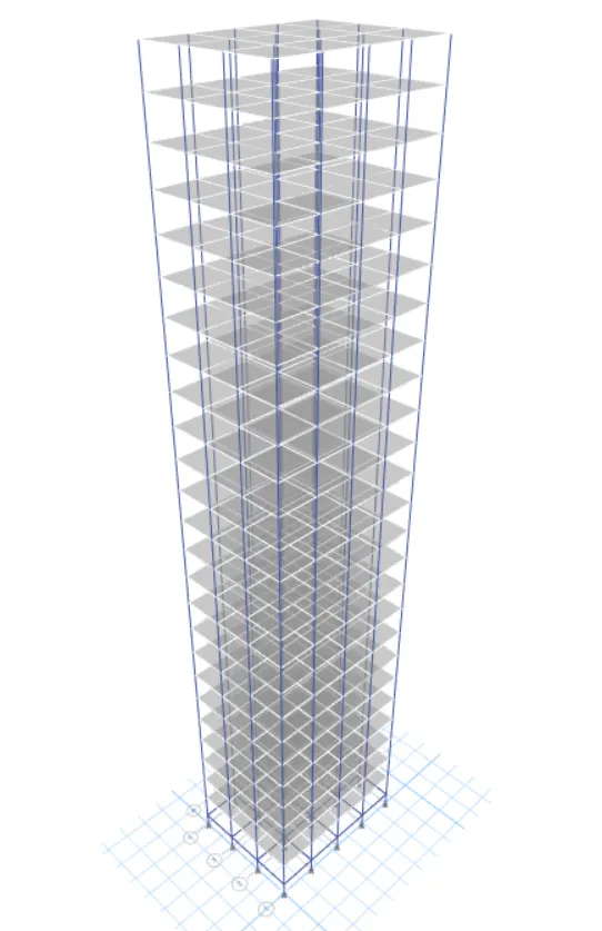
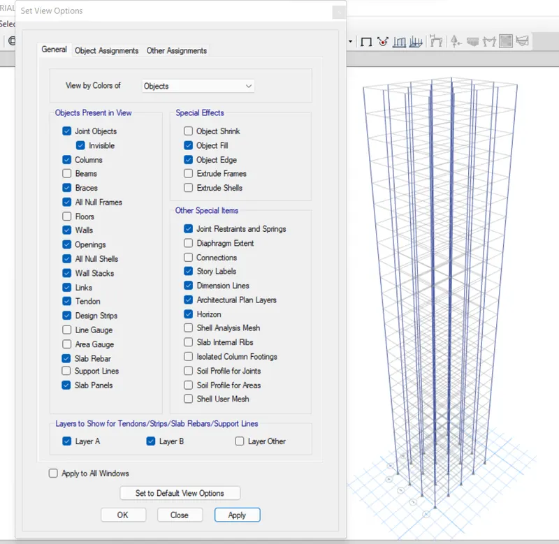
- Set Building Limit from 1-10
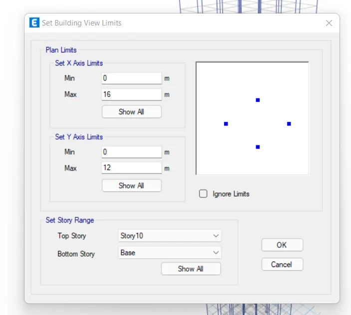
- Select all the Columns and Assign C800x800 Section
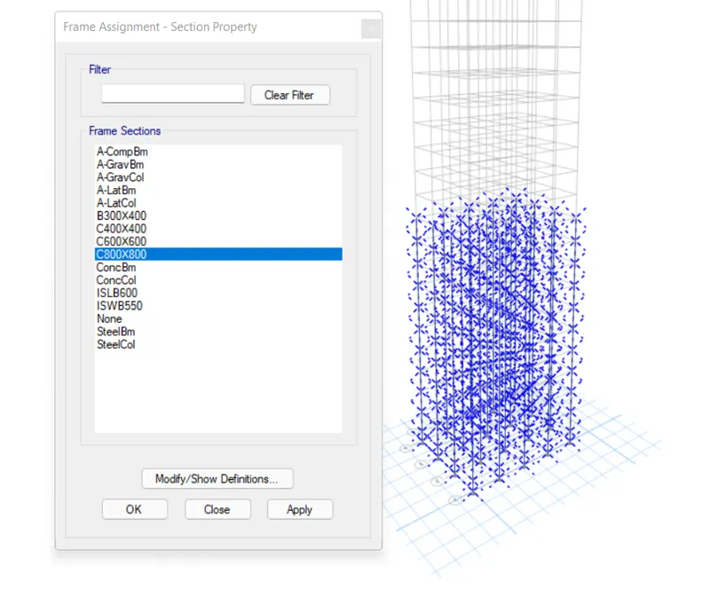
- To Set Building Limit 11-20
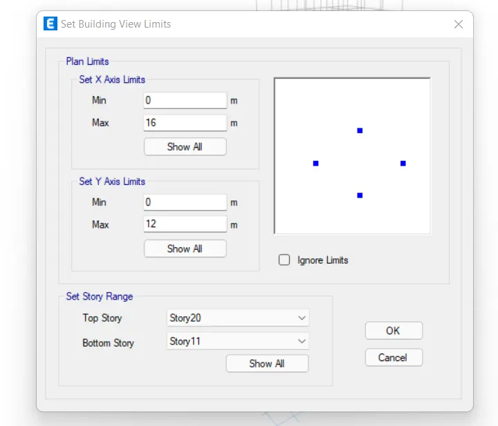
- Select all the Columns and Assign C600x600 Section
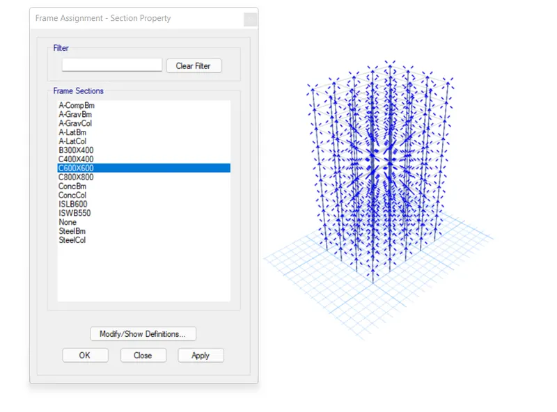
- Set Building Limit 20-25
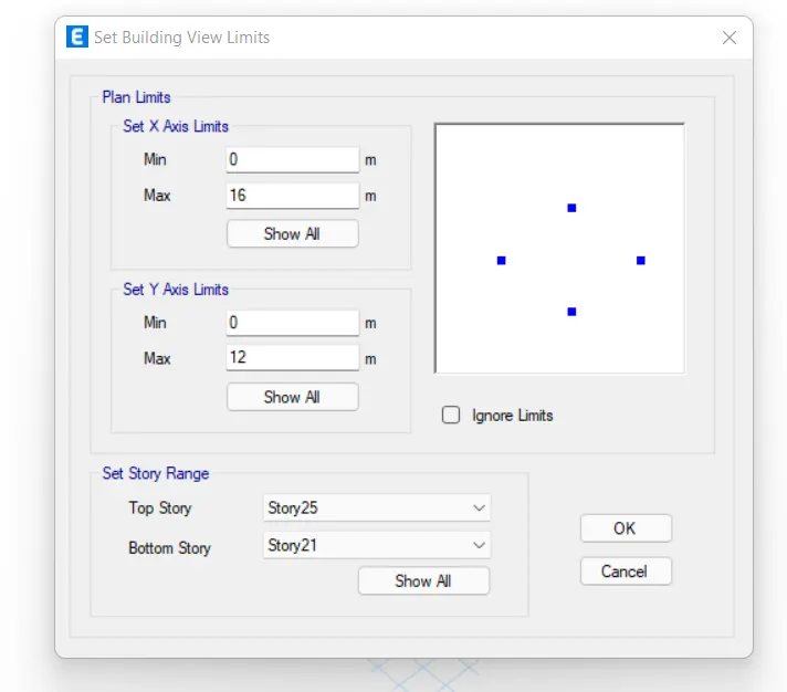
- Select all the Columns and Assign C400x400
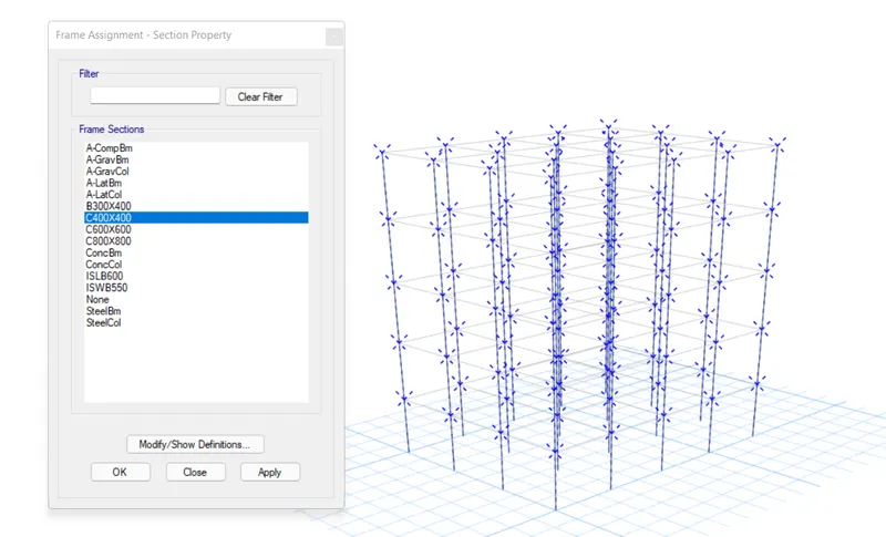
- Run the Analysis
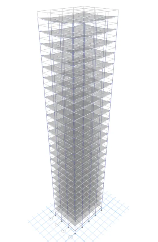
- Modal Response for Building G
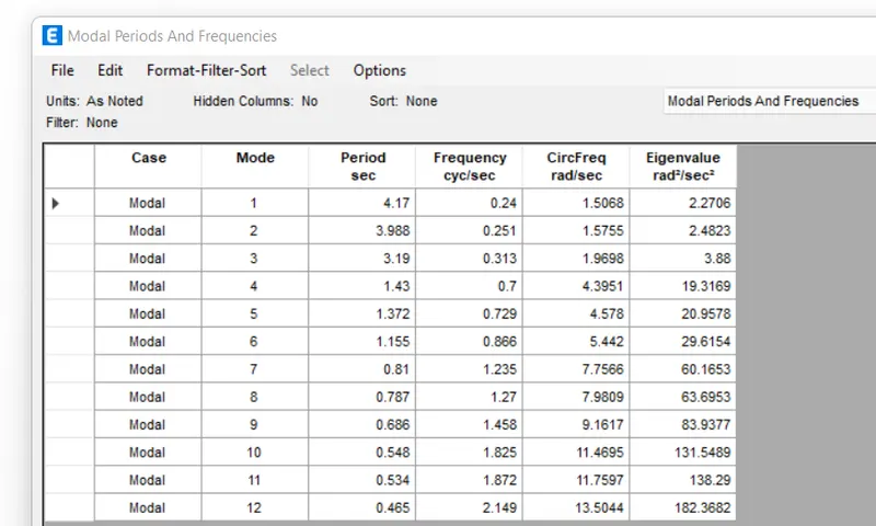
8. BUILDING "H" (G+25)
Consistent column size throughout the building: C800X800
PROCEDURE:
- This is the same model as the previous one. All we need to do is assign the column section as C800x800 for the entire structure which can be done by simply selecting all the columns>go to assign>select C800x800>click ok and done. Thus the same procedure is listed down below for better understanding.
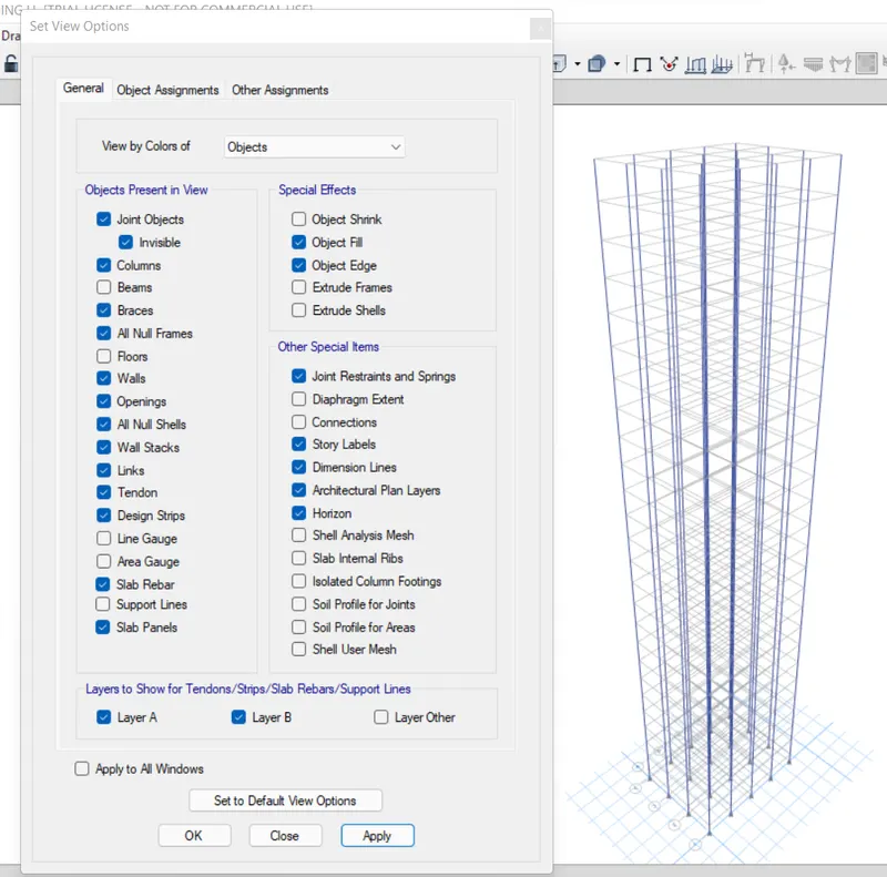
- Select All the Columns and Assign C800x800 Section
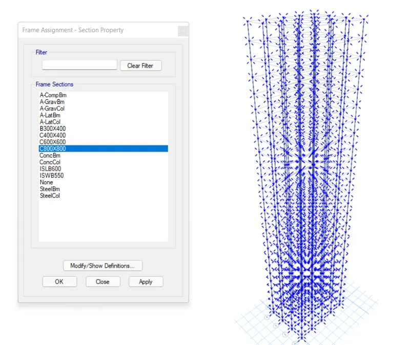
- Run the Analysis
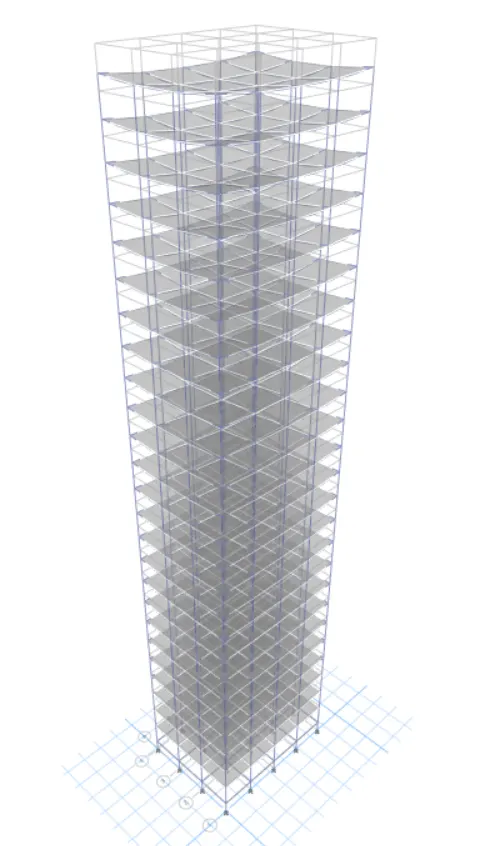
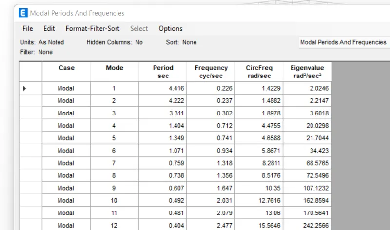
- Modal Response for Building H
9. BUILDING "J" (G+25)"
10% increment in the imposed loads
PROCEDURE:
- Building J is the exact copy of the model H and we don't need to alter anything related to the modeling. However, we need to increase the imposed load on the building by 10% which is assigned as 3KN/m^2 on all slabs of the building. So, the procedure to do the same is listed down below:
- Select the S150 Slab Section
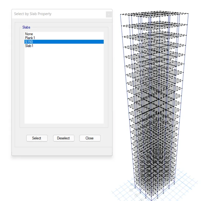
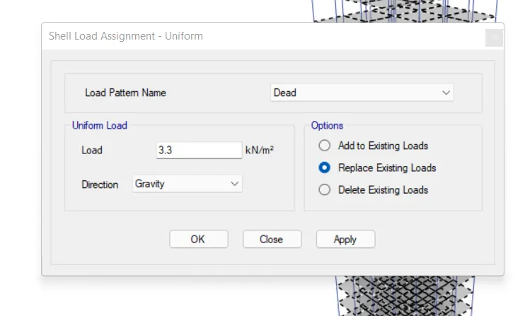
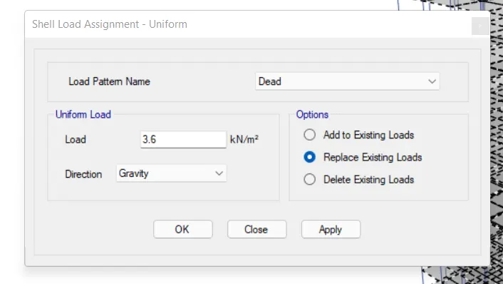
- Go to Assign>Shell loads>Uniform>increase it by 10%
- We have assigned a 3KN/m^2 imposed load on all slabs for all of our previous buildings
- So, we need to increase that by 10% meaning we need to replace the existing imposed load with 3.3 KN/m^2
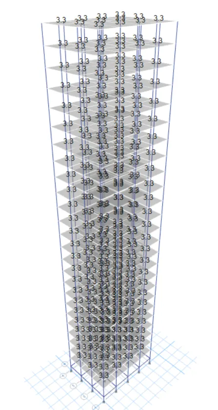
- Run the Analysis
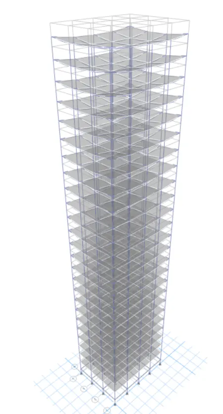
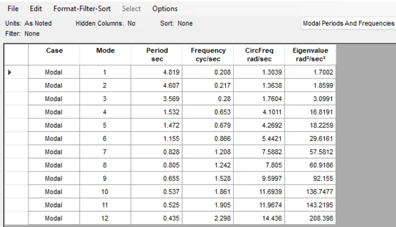
- Modal Response for Building J
10. BUILDING "K" (G+25):
20% increment in the imposed loads
PROCEDURE:
- For this model, we can follow the exact procedure as we did for building j. However this time, we need to increase the live load by 20% as opposed to 10%. So, the stepwise procedure has been listed down below
- Select the S150 Slab section
- Assign 3.6 KN/m^2 distributed shell load for a 20% increase
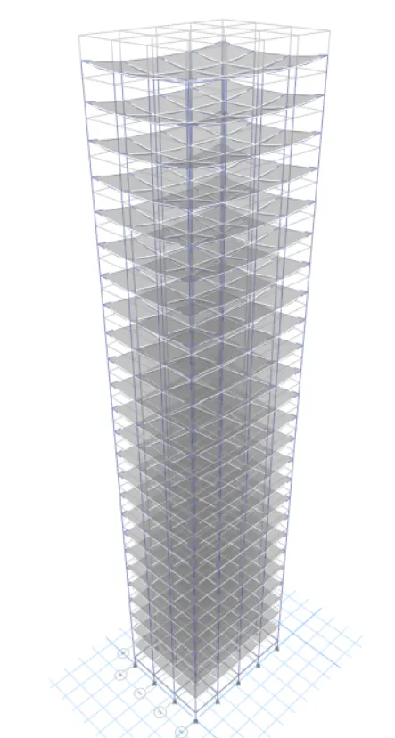
- Run the Analysis
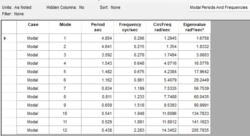
- Modal Response for Building K
RESULT:
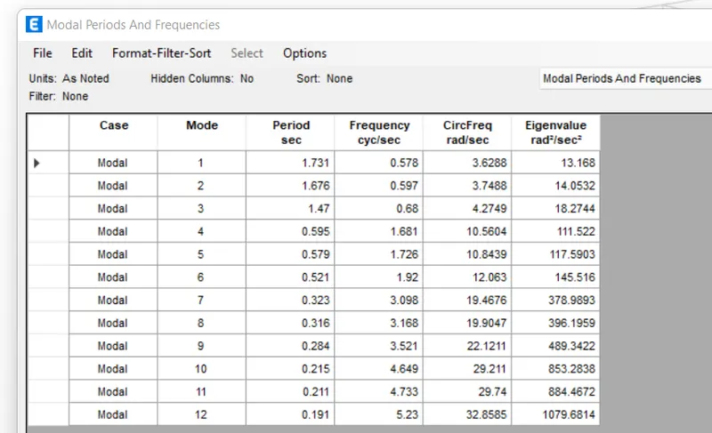
For Comparing the fundamental natural periods of buildings E & F as well as G & H
- The fundamental natural period of building E is 1.731 sec
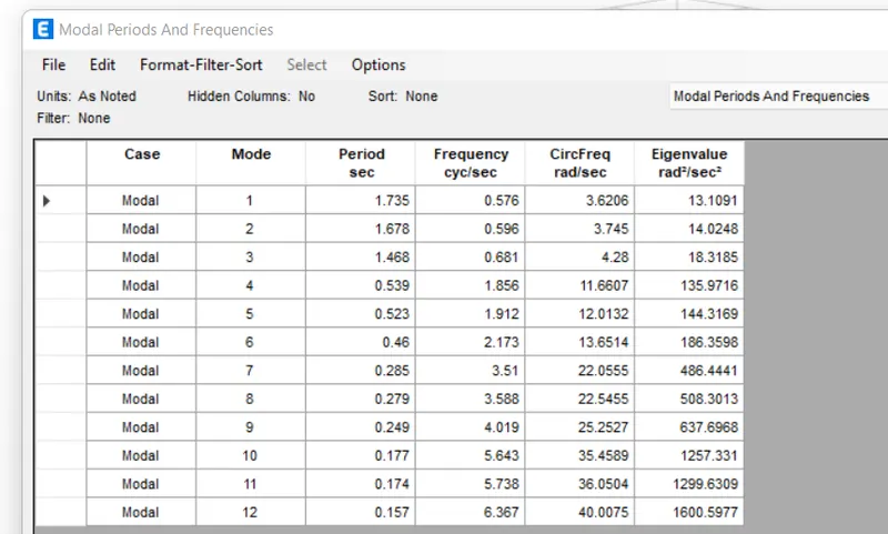
- The fundamental natural period of building F is 1.735 sec
- The fundamental natural period of building G is 4.17 sec
- The fundamental natural period of building H is 4.41 sec
- Since we used two different column size in E building and used only one type of column for F building, caused the significant change in the time period. The same has happened with the case of G and H
For Comparing the fundamental natural periods of buildings H, J and K
- The fundamental natural period of building H is 4.41 sec
- The fundamental natural period of building J is 4.81 sec
- The fundamental natural period of building K is 4.85 sec
- When comparing the Natural period of Buildings H,J and K, the time period remains constant, which means, a small increment in the live load causes no change in thw stiffness and flexibility of the structure.
- While a significant change in the structural flexibility can be expected with greater increament in live load.
- Thw weight of the building is directly proportional to the flexibility of the structure.
For Comparing the fundamental natural periods of Buildings A, B, F and H change with change in building height
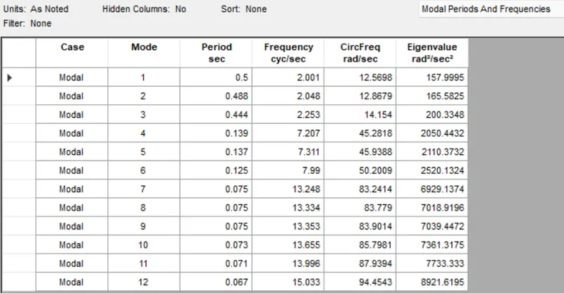
- The fundamental natural period of building A is 0.5 sec
- The fundamental natural period of building B is 1.03sec
- The fundamental natural period of building F is 1.73 sec
- The fundamental natural period of building H is 4.41 sec
- When observing the height and the natural period of building A,B, F and H, it can be observed that, whith the increase in height of the structure, the natural period of the building also increases.
For Comparing the fundamental natural periods of Buildings B, C and D change with change in column orientation
- The maximum story drift of building B is 2.25 sec
- The maximum story drift of building C is 2.1 sec
- The maximum story drift of building D is 2.45 sec
Effect of Flexural Stiffness of Structural Elements on mode shapes: Compare fundamental mode shape of Building B in two situations when the flexural stiffness of beams relative to that of adjoining columns is very small versus when it is large
- The maximum flexural stiffness of Beam Building B 100% is 1.036 sec
- The maximum flexural stiffness of Beam Building B 10% is 2.627 sec
- The maximum flexural stiffness of Column Building H 100% is 4.41 sec
- The maximum flexural stiffness of Column Building H 10% is 5.99 sec
- Effect of Degree of Fixity at column bases on mode shape: Compare the fundamental mode shape of Building B in two situations when the base of columns is pinned versus when it is fixed.
- The Pineed natural period of building B is 1.036 sec
- The Pineed natural period of building B is 0.94 sec