Project 1_Comparative study of different storey buildings for Seismic forces
AIM :
To design, model and analysis the different building with the column specification using E-Tabs, and comparing the various factors changes due to the differernt factors and specification changes.
PROCEDURE IN DETAIL:
- Firstly Open the Etabs software.
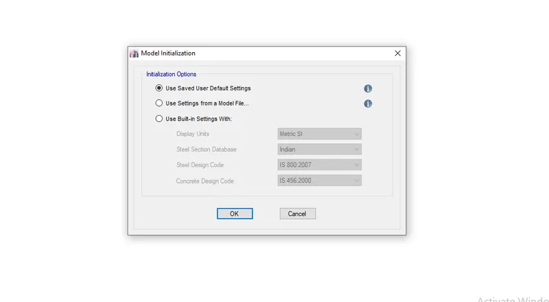
- Select the built in setting with:
- Check the display unit, steel design, steel desing code, concrete design > OK.
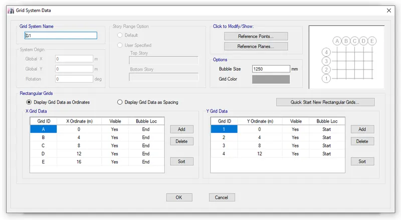
- The next dialog box take us to the grid and storey height settings.
- Select the custom grid and storey option.
- All the building have 4 bays on X axis and 3 bays Y axis, with the interval of 4m between every column and 3m height.
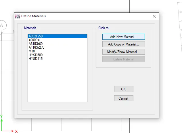
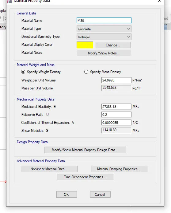
- Add the material property by define > material property > (NDW) > add new material > material name as M30 > Material type as Concrete > OK.
- Follow the same procedure for the rebar.
-
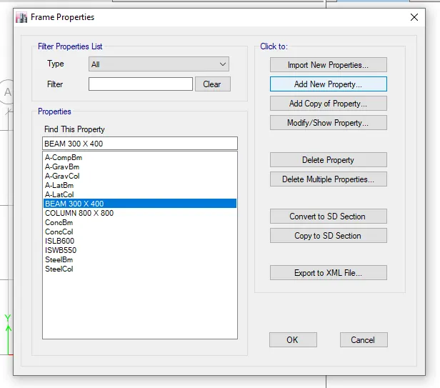
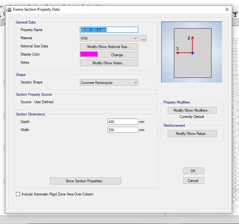
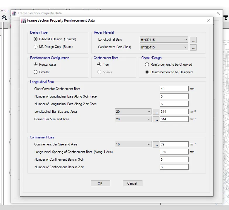
Add the beam, define > section property > frame section > add new property > select the beam shape > name the beam size 300mm x 400mm > feed the depth and the width > Select the m3 design beam only > set the rebar to HYSD 415.
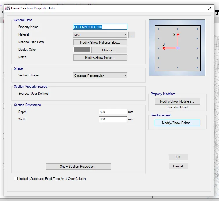
- Column property is added in with the same procedure as the followed to the Beam, with the dimension as 400mm x 400mm.
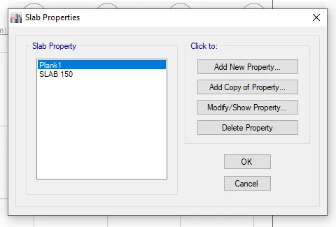
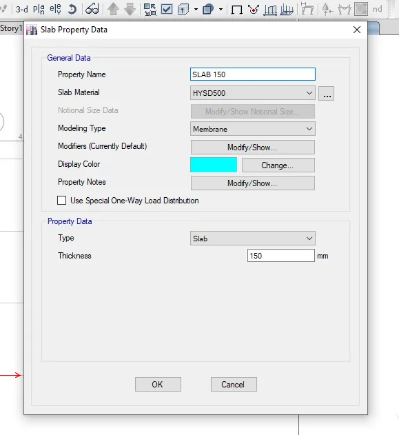
- Add the slab property . define > section property > slab section > add a new property > name it as SLAB 150 > slab material m30 > modelling type as membrane > feed the thickness as 150 mm.
ASSIGNING THE LOAD:
Assign the loads to the building by,
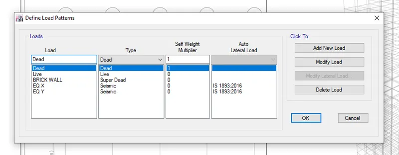
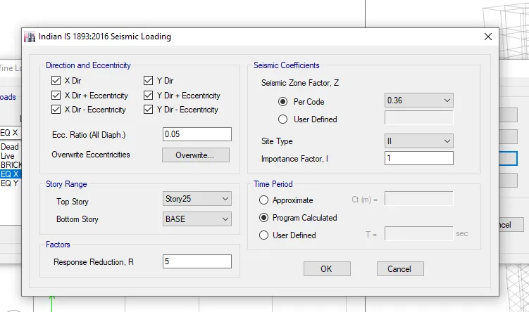
- define > load pattern > NDB > ADD THE DEAD LOADS, LIVE LOAD, WALL LOAD as super load, SEISMIC LOAD on the X direction and the Y direction, assign the lateral load to the X and the Y direction, set the reduction factor, zone and soil type.
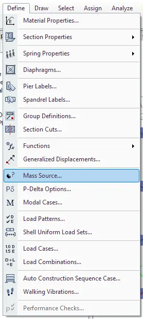
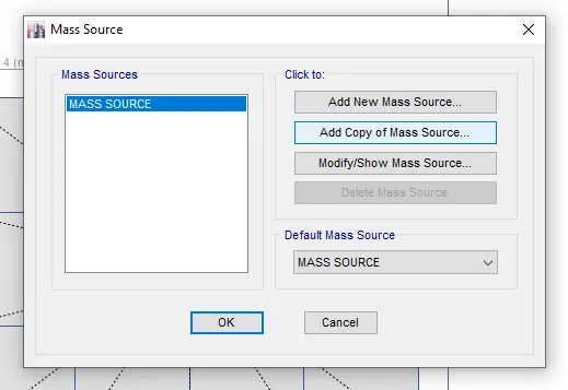
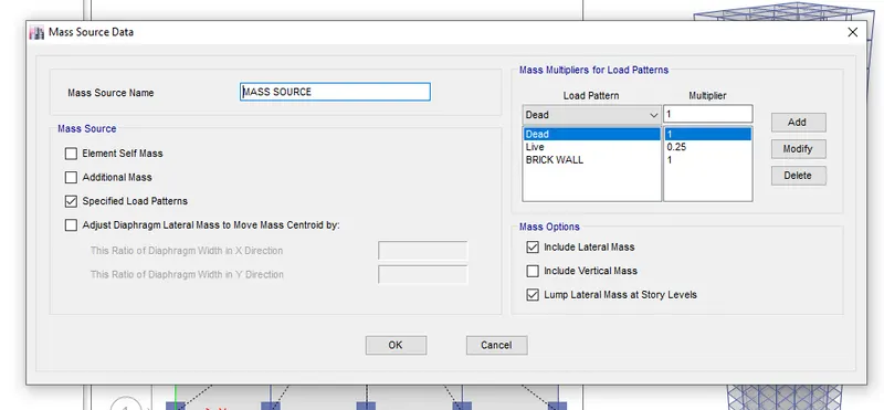
- Set the mass source,
- define > mass source >(NDB) > add the full dead load, full wall load, 25% of the live load.
- Live load on the slab and the brick wall on the beam is assigned after the building modelled.
- THE MODEL IS NOW AT THE STAGE TO START THE DRAWING.
MODEL A
2 STOREY BUILDING:
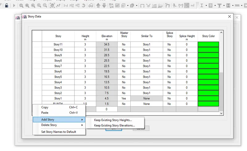
No.of.storey: 2 (Add 2 storey on the storey option with height of 3m, and plinth height of 1.5m)
column size: 400mm x 400mm.
(set the drafting area as all storey while drawing the coluymn and beam) Pick the quick draw column and place the column on the all the center point of the grids.
Pick the quick draw beam option and sect all the grid lines where the beam are suppose to be.
Pick the quick draw slab and pick the slab (with the draw area as similar storey).
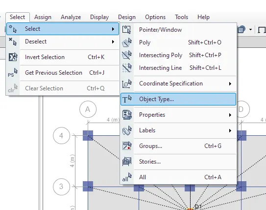
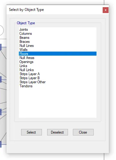
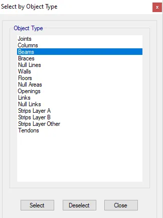
Select the slab on the all storey(select > select > object type > floor)
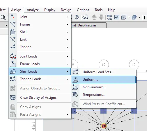
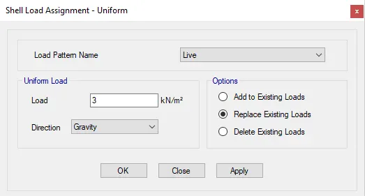
After selelcting the slabs, assign the live load to the slabe(assign > shell load > uniform > choose the load as load > feed the load as 3 kN/M^2)
Select the beams by the same way did on the slab.
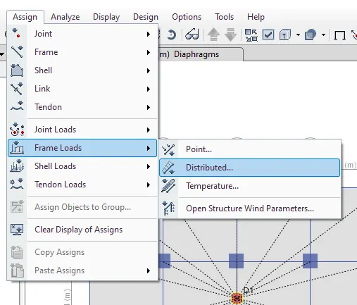
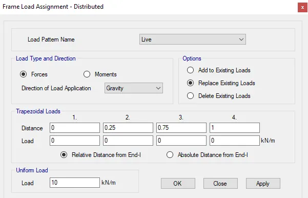
assign > frame load > distributed > change the load type as brick wall > feed the load as 10 kN/m .
Set the modal case limit as 1 to 12.
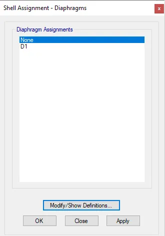
set the diaphragm for all the slabs, (assign > shell > diaphragm > select D1.)
check for the before running the analysis.
Now run the analysis.
Save as; the model as MODEL B
MODEL B
since the column size same as the model A and the Loads and the mass source has been applied, all I had to do is modify the no. of. storey (g o to edit > edit storey and grid system > NDB > modify storey data > add 3 more storey and refresh.)
Assign the live load and super dead load (brick wall) on the newly added storey.
Set the diaphragm to all the slabs (assign > shell > diaphragm > select D1)
And the model is ready to analyze.
Click the analyze button. Save as; the file as MODEL C
Proceed to work on the next nodel.
MODEL C
So, this building has the same no.of.storey but the size of the column is different (550 mm x 300mm).
So what should be done is add new column property with the dimension of (550mm x300 mm). name the property as column 550 x 300
now make dissappear the slab and beams from the plan by clicking tick icon on the toolbar, has the list structural elements, there uncheck the floor and beam.
change the view into 3d select all the columns > assign > section property > pick the column 550 x 300.
Now the column dimesion is changed into 550mm x 300mm
If the columns are oriented along the X axis to rotate the columns go to assign > frame > local axes > NDB > enter 90 degree on the angle option.
Set diaphragm to all the slabs.
Check and run the analysis.
Save as; the model as the MODEL D.
MODEL D:
So, this building has the same no.of.storey but the size of the column is different (300mm x 550mm).
In the last model the column is oriented along the X axis, and the columns in this model has to be oriented along the Y axis (go to assign > frame > local axes > NDB > change the angle to 90 DEGREE.
Now the column is oriented to Y axis.
Set the diaphragm to all the slabs.
Check the model and run the analysis.
save as; the model as MODEL E.
MODEL E:
Since this model has two diffrent column dimension
base to storey 5 : 600mm x 600mm
storey 6 to storey 10 : 400mm x400mm
Now add the extra 5 storey on the edit the grid and storey option.
And add the live load on the all slabs and wall load on all the beams.
Now about the column sizes, add the new column property with the dimension of 600mm x 600mm and another column with the dimesion of 400mm x 400mm.
And name them column 600 x 600 and column 400 x 400.
Now uncheck the beam and floor and make them dissappear.
Now the columns on the floors base to storey 5 to be selected.
Go to view > set the building view limit > set it from base to storey 5.
Now only the floors from base to storey 5 is going to appear on the screen.
Select all the column > assign > section property > frame section > select the column 600 x 600.
And the column size from the base to storey 5 is changed.
Do the same procedure for top 5 storey, and replace them columns with column 400 x 400.
Set the diaphragm to all the slabs.
Check the model and run fro analysis.
save as; the model as MODEL F.
MODEL F
In this model all the column size is 600 x 600, so go to view > the building view limits > set the range from storey 6 to storey 10.
Uncheck the beam and floor, go to assign > section property > frame section > column 600 x 600.
Now the all the column size is been changed into 600mm x 600mm.
Set the diaphragm to all the slabs.
check the model and run for analysis .
save as; the model as MODEL G.
MODEL G:
This is a 25 storey model with 3 different size of column on the different set of storeys.
so create new column property of three diffrernt dimension namely:
bottom 10 floors: 800mm x 800mm
middle 10 floors: 600mm x 600mm
top 5 floors: 400mm x 400mm
With the help of set building view limit, view the different set of storeys.
And assign the column 800 x 800 to bottom 10 storeys
assign the column 600 x 600 to the middle 10 storeys and assign the column 400 x 400 to the top five storeys.
The model is no wready to analysis.
Check the model for error and run the model for Analysis.
save as; the model as MODEL H.
MODEL H
This model has the columns with size of 800mm x 800mm on all the storeys.
So Go to view > set the building view limits > NDB > set the range from storey11 to storey 25 , because the columns on the bottom 10 floors has been set as 800mm x 800 mm from the last model.
assign the selected column to column 800 x 800.
now the model can be checked and run for analysis
save as; the model as MODEL J.
MODEL J:
This model has no structural specification change from the last model, but the live load on the slab is 10 % higher than the last model which means the ll is 3.3 KN/M
What has to be done here is change the live load to 3.3 KN/m
go to select > select > object properties > floors > assign > shell loads > NDB > Assign the live load as 3.3 kN/m .
Set the diaphragm for all the slabs.
Now run the model for analysis.
save as; the model as MODEL K.
MODEL K:
This model is same as the last one but the live load is 20% higher than the normal loads.
So select all the slabs and assign the shell loas as 3.6 KN/m .
Set the diaphragm for all the floors and run the model for analysis.
RESULT AND REPORT:
Comparing the factors:
Effect of stiffness T :
1)MODEL E: 1.737 s
MODEL F: 1.737 s
2)MODEL G: 2.50 s
MODEL H: 2.21 s
Effect of mass on T:
1)MODEL H: 2.21 s
2)MODEL J: 2.22 s
3)MODEL K: 2.22 s
Effect of building height on T:
1)MODEL A: 0.5 s
2)MODEL B: 1.038 s
3)MODEL F: 1.77 s
4)MODEL H: 2.21 s
The time period value gradually increases when the height of the building is increased.
Effect on column orienation on T:
1)MODEL B: 1.038 s
2)MODEL C: 1.145 s
3)MODEL D: 1.121 s
The columns in model c are orinened along the x axis, and the columns on the model are oriented on the Y direction.
Maximum storey displacement and the reaction of the building to the lateral load is completely opposite on some modes.
So the column orientation plays an important roll on the stability of the building.
Effect of flexural stiffness of structural element on model shapes:
MODEL B:
FOR FULL FULEXURAL STIFFNESS: 1.03 s
FOR FLEXURAL STIFFNESS CLOSE TO ZERO: 2.63 s
To do run the analysis for this criteria
open the MODEL B release the lock.
Go to
Define > Section property > frame section > select the beam 300x400 > modify > select property modifier > change the moment of inertia to 0.
Run the model for analysis.
TAKE THE VALUES FROM THE TABLE.
EFFECT OF FLEXURAL STIFFNESSON VERTICAL MEMBER :
on MODEL H
Axial cross section of column close to nil(15%): 5.432 s
Full axial cross section of column : 4.41 s
To run this model to analysis
Take the time period value from the table.
EFFECT OF DEGREE OF FIXITY ON MODEL B:
All we have to do is change the joint of the foundation to fixed from pinned.
Set plan sheet on base plan.
Select all the grid centers, Go to assign > joint > restrains > select the fixed joint option.
And run the model for analysis.
Get the value fro time period from the table.