Project 1_Comparative study of different storey buildings for Seismic forces
AIM
To model and analyse 10 buildings for a comparative study of different storey buildings for Seismic force.
INTRODUCTION
ETABS is an engineering software product that caters to multi-story building analysis and design. Modeling tools and templates, code-based load prescriptions, analysis methods and solution techniques, all coordinate with the grid-like geometry unique to this class of structure.
PROCEDURE
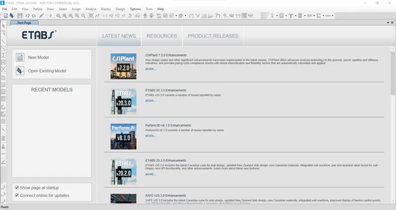
- Open ETABS Software
Building A


STEP 1: Model Initialization
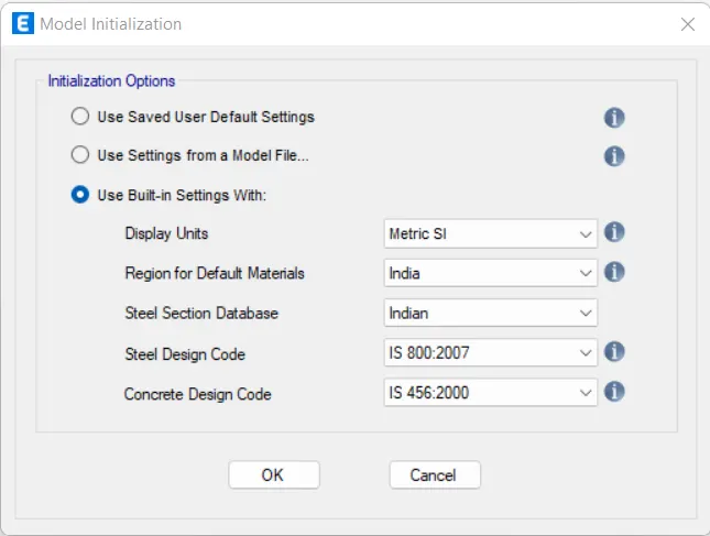
- Click 'New Model' and select 'Use Built-in Settings With:'
- Assign all options as given below
- Click 'OK'
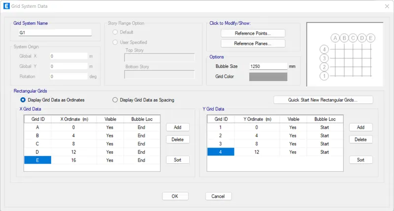
STEP 2: Grid Spacing
- Click 'Custom Grid Spacing'
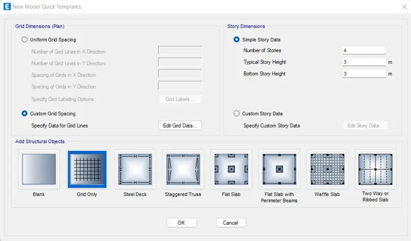
- Click 'Edit Grid Data'
- Add 'X Grid Data' with 4m increase for 4 times
- Add 'Y Grid Data' with 4m increase for 3 times
- Click 'OK'
STEP 3: Story Data
- Click 'Custom Story Data'
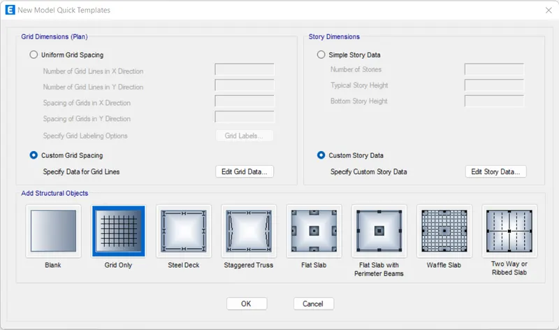
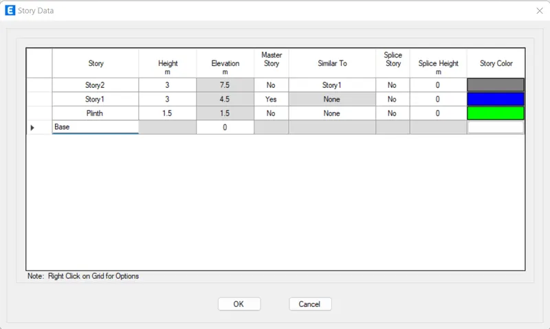
- Click 'Edit Story Data'
- Assign 'Story' and 'Height' as shown in this figure
- Assign 'Story1' as the 'Master Story'
- Assign 'Story2' as 'Similar To' 'Story1'
STEP 4: Material Properties
- Click 'Material Properties' under the 'Define' tab

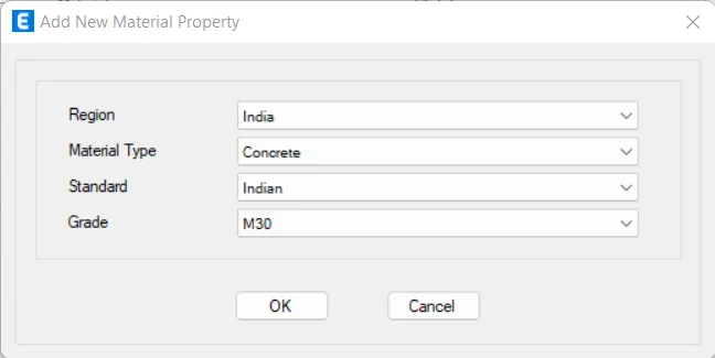
- Click 'Add New Material'
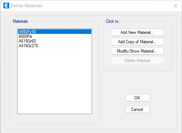
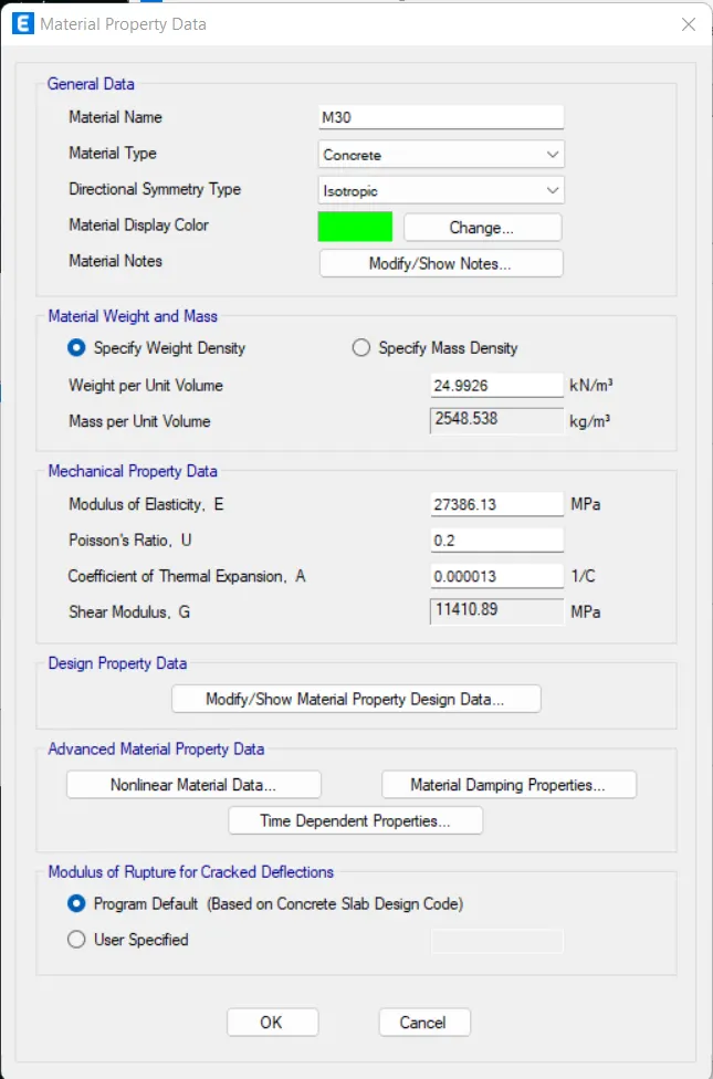
- Assign all options as given below
- Click 'OK'
- Click 'OK'
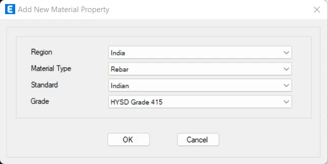
- Click 'Add New Material'
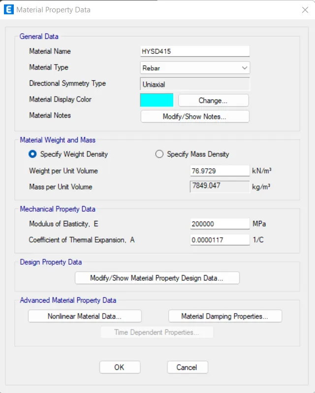
- Assign all options as given below
- Click 'OK'
- Click 'OK'
STEP 5: Add Beam Properties
- Click 'Frame Section' in the 'Section Properties' under the 'Define' tab

- Click 'Add New Property'
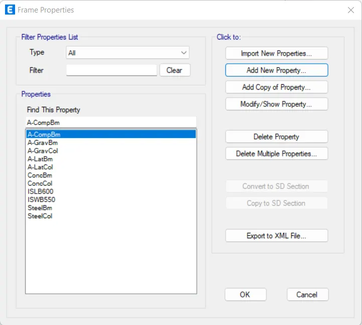
- Click 'Rectangular Section'
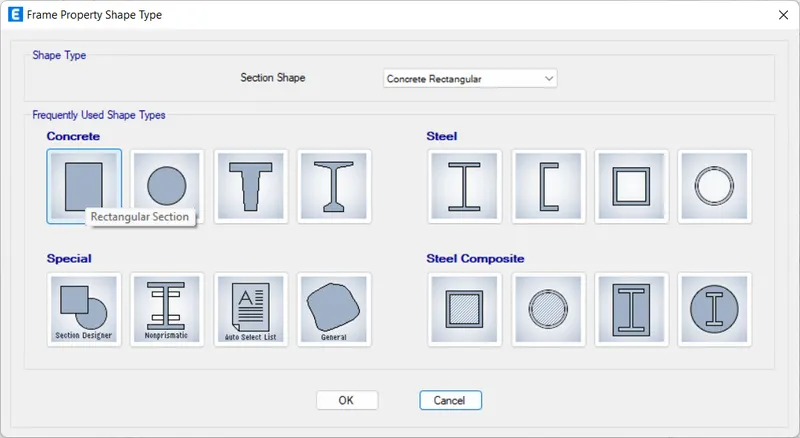
- Assign all options as given below
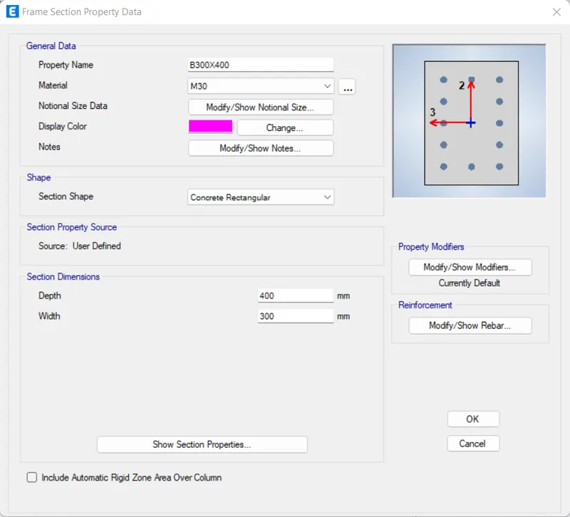
- Click 'Modify/Show Rebar'
- Assign all options as given below
- Click 'OK'
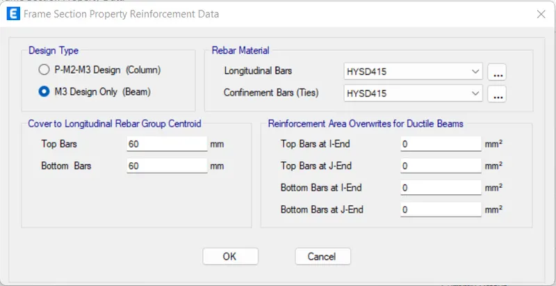
- Click 'OK'
STEP 6: Add Column Properties
- Click 'Frame Section' in the 'Section Properties' under the 'Define' tab
- Click 'Add New Property'
- Click 'Rectangular Section'
- Assign all options as given below
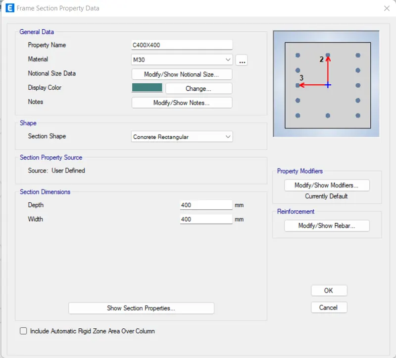
- Click 'Modify/Show Rebar'
- Assign all options as given below
- Click 'OK'
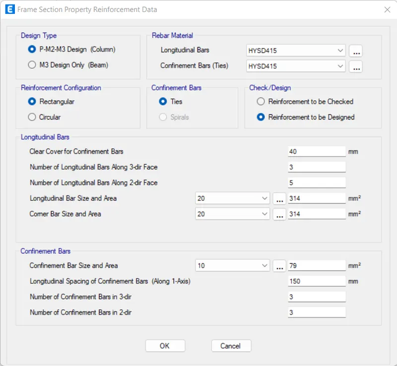
- Click 'OK'
STEP 7: Add Slab Properties
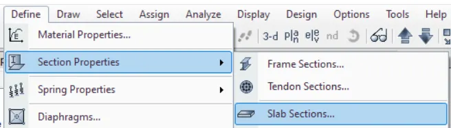
- Click 'Slab Section' in the 'Section Properties' under the 'Define' tab
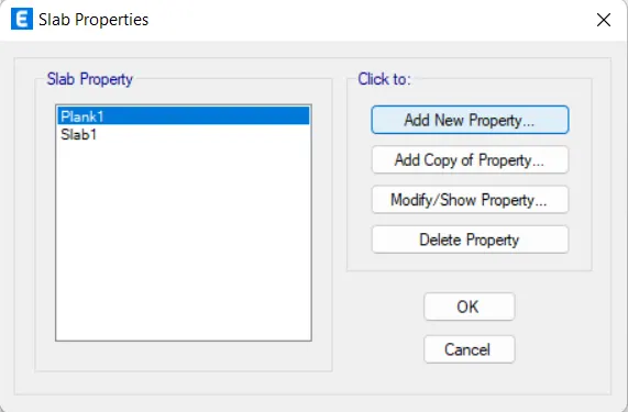
- Click 'Add New Property'
- Assign all options as given below
- Click 'OK'
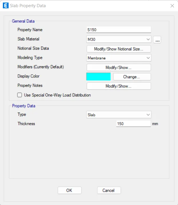
- Click 'OK'
STEP 8: Add Load Patterns
- Click 'Load Patterns' under the 'Define' tab
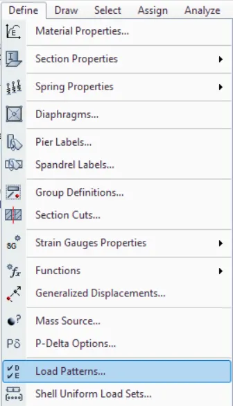
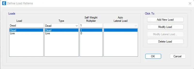
- Apply all loads
- After defining a load, click 'Add New Load'
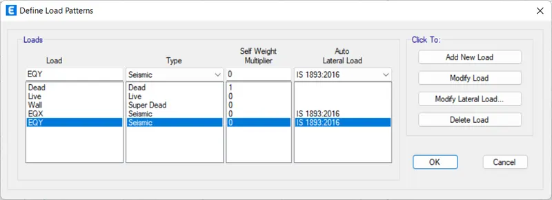
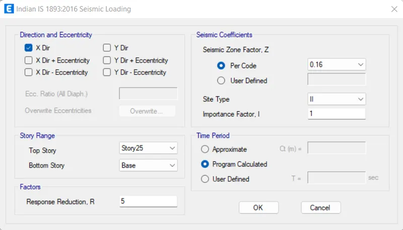
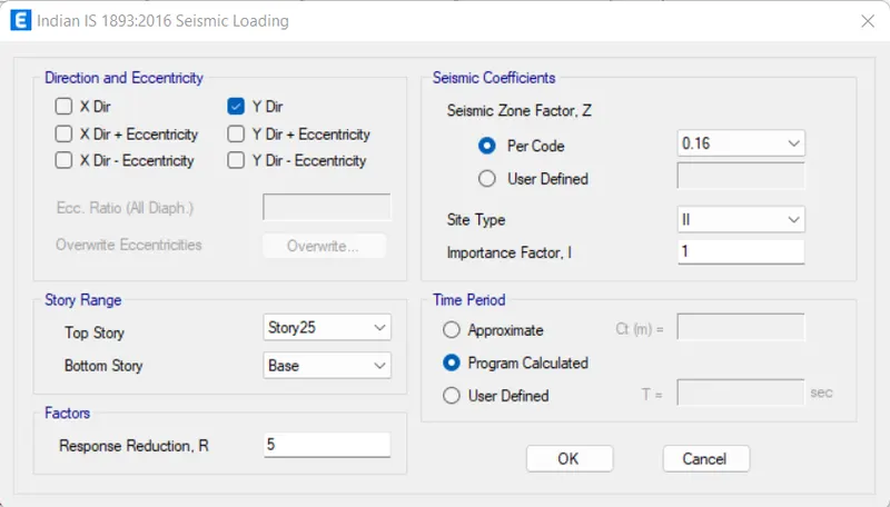
- Click 'Modify Lateral Load' for load 'EQX' and 'EQY'
- Settings for EQX
- Assign all options as given below
- Click 'OK'
- Settings for EQY
- Assign all options as given below
- Click 'OK'
- Click 'OK'
STEP 9: Add Mass Source Data
- Click 'Mass Source' under the 'Define' tab
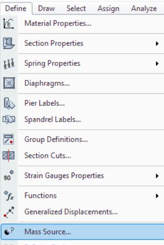
- Click 'Modify/Show Mass Source'
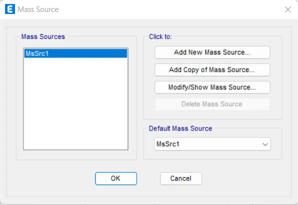
- Assign all options as given below
- Click 'OK'
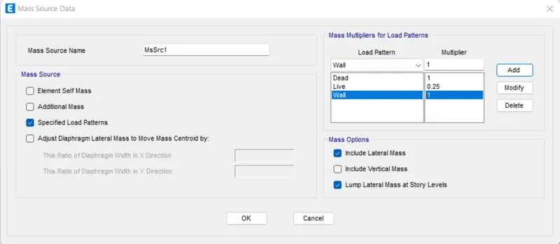
- Click 'OK'
STEP 10: Load Combinations
- Click 'Load Combinations' under the 'Define' tab
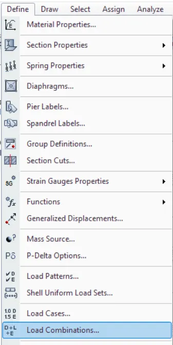
- Click 'Add Default Design Combos'
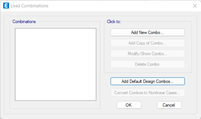
- Select 'Concrete Frame Design' and 'Convert to User Combinations'
- Click 'OK'
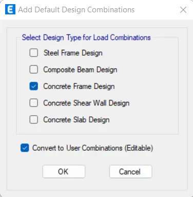
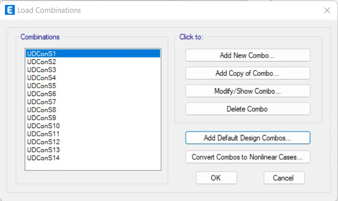
- Click 'OK'
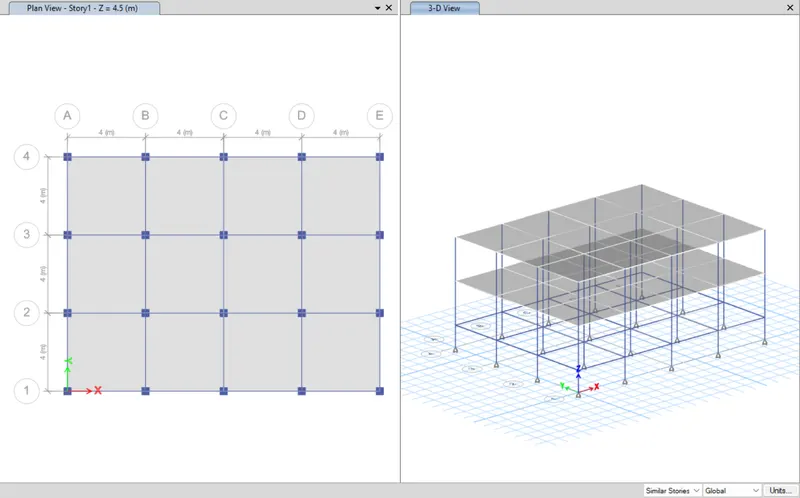
STEP 11: Add Columns, Beams and Slabs
- Click 'Quick Draw Columns' from the toolbars
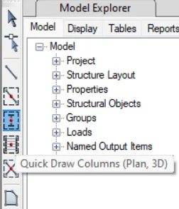
- Assign 'C800X800' as the property
- Select 'All Stories'
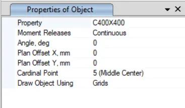
- Place the columns on grids
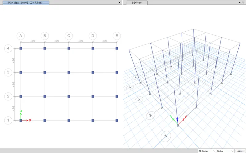
- Click 'Quick Draw Beams' from the toolbars
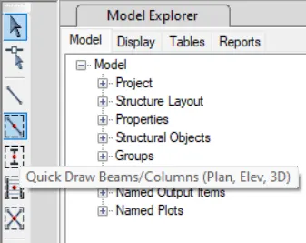
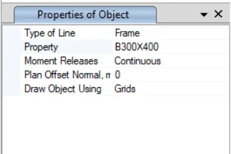
- Assign 'B300X400' as the property
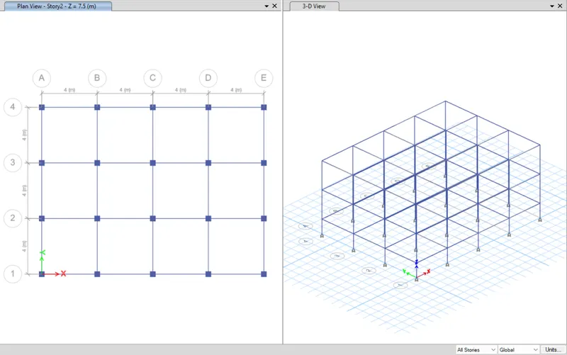
- Place the beams on lines
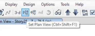
- Click 'Set Plan View' from top menu
- Select 'Story1' and click 'OK'
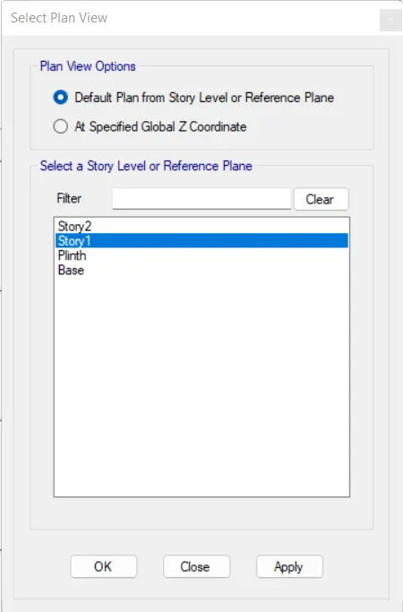
- Select 'Similar Stories' on the bottom right menu
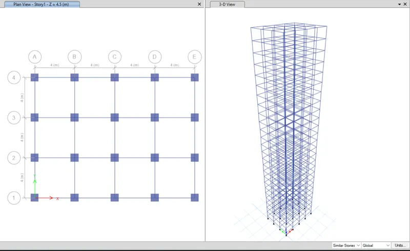
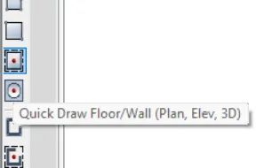
- Click 'Quick Draw Floor/Wall' from the toolbars
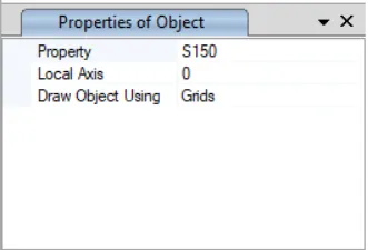
- Assign 'S150' as the property
- Click inside all the grids
STEP 12: Assign Loads
- Click 'Frame Sections' in the 'Properties' under the 'Select' tab
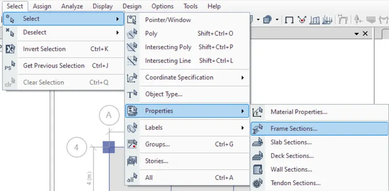
- Click 'B300X400' and click 'Select'
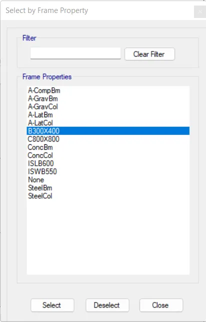
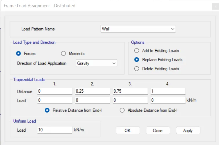
- Click 'Distributed' in the 'Frame Loads' under the 'Assign' tab
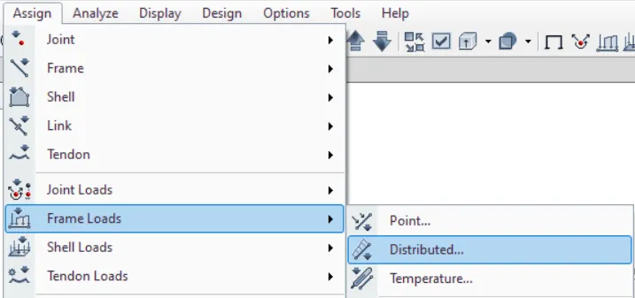
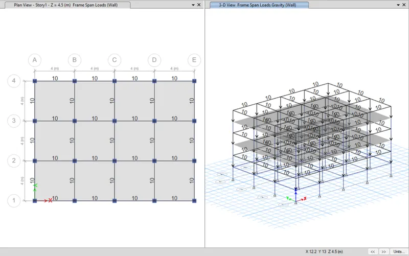
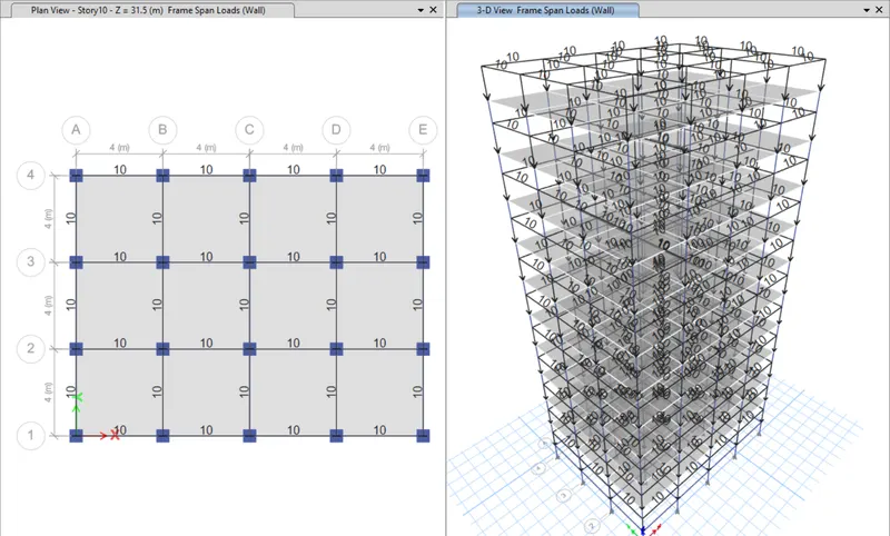
- Assign 'Wall' load as 10KN/m as shown below
- Click 'Apply'
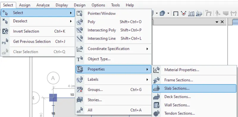
- Click 'Slab Sections' in the 'Properties' under the 'Select' tab
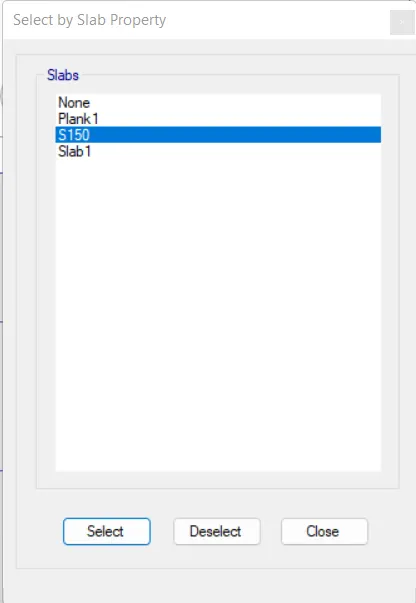
- Click 'S150' and click 'Select'
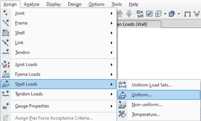
- Click 'Uniform' in the 'Shell Loads' under the 'Assign' tab
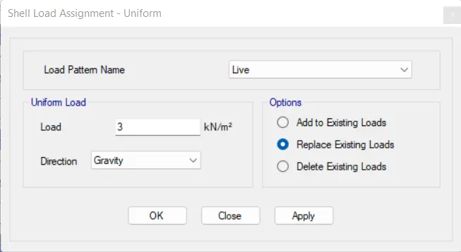
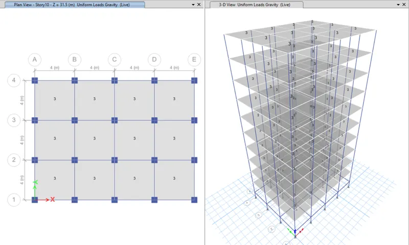
- Assign 'Live' load as 3KN/m2 as shown below
- Click 'Apply'
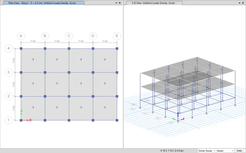
- Repeat the above procedure for selecting all slabs
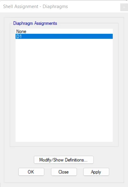
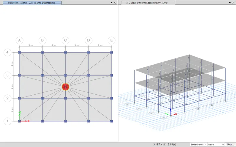
- Click 'Diaphragms' in the 'Shell' under the 'Assign' tab
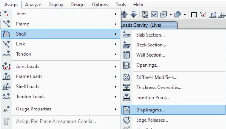
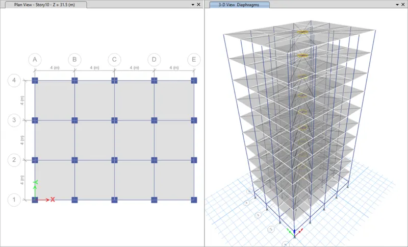
- Select 'D1' and click 'Apply'
STEP 13: Run Analysis
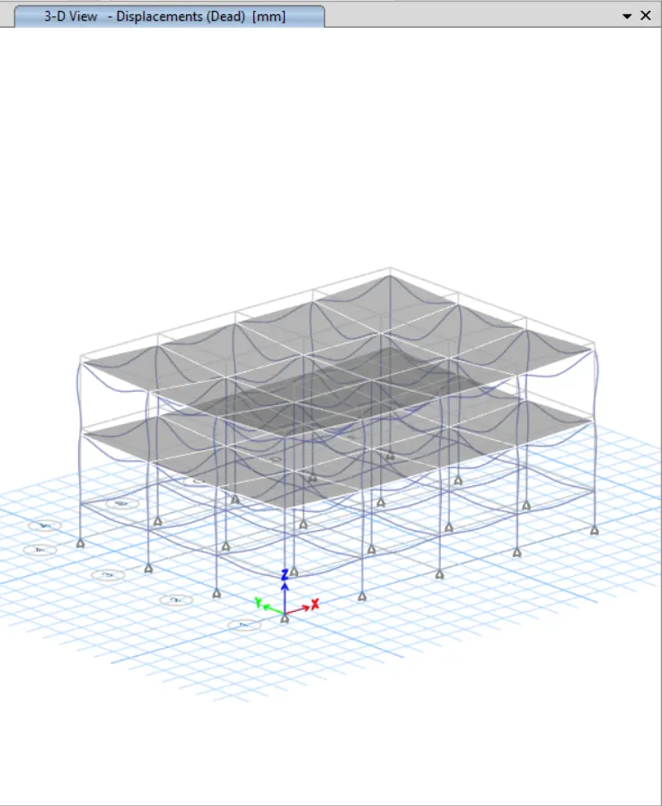
- Click 'Run Analysis' from top menu
STEP 14: Model Tables
- From 'Model Explorer', select
- ANALYSIS RESULTS > Structure Output > Modal Information > Table: Modal Periods And Frequencies
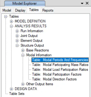
- Right click and then click 'Show Table'
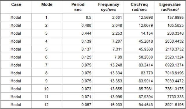
Model Response for Building A
Building B

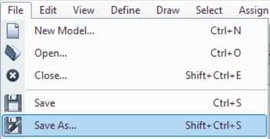
STEP 1: Save the Model
- Click 'Save As' under the 'File' tab
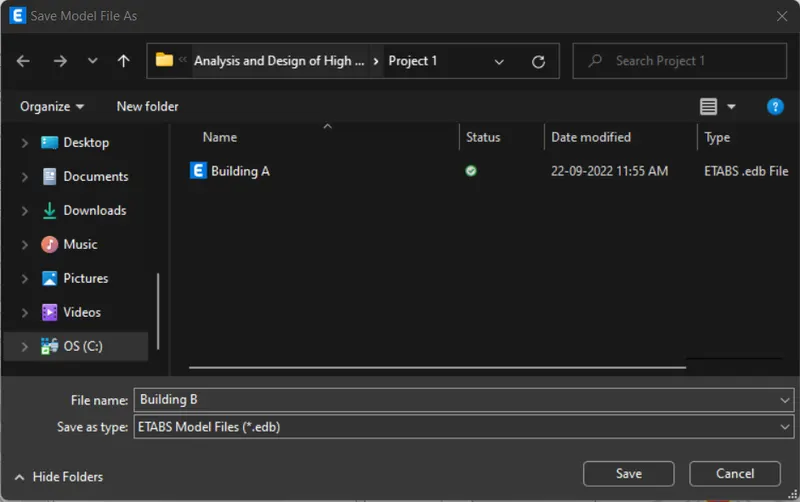
- Give file name as 'Building B' and click 'Save'
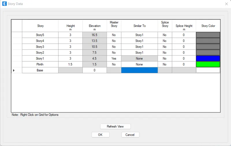
STEP 2: Add Stories
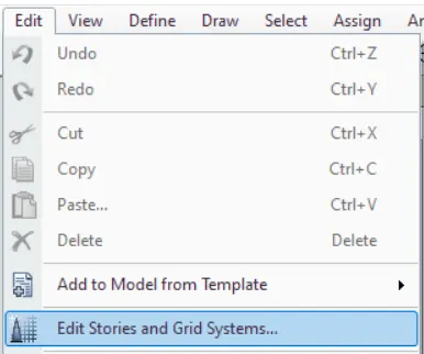
- Click 'Edit Stories and Grid Systems' under the 'Edit' tab
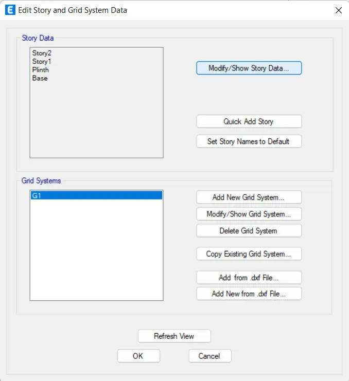
- Click 'Modify/Show Story Data'
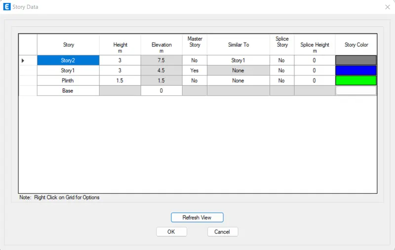
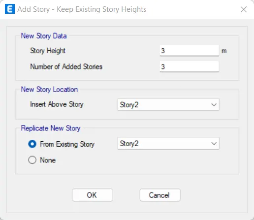
- Click 'Add Story' by right-clicking
- Assign 'Number of Added Stories' as '3'
- Click 'OK'
- Click 'OK'
- Click 'OK'
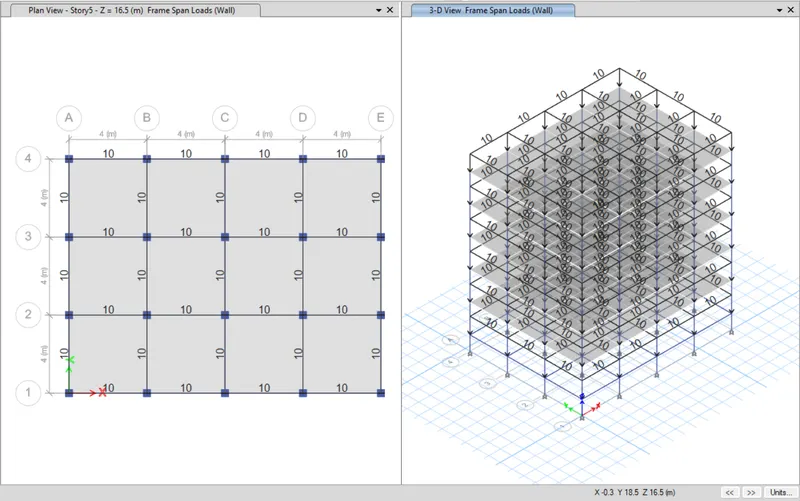
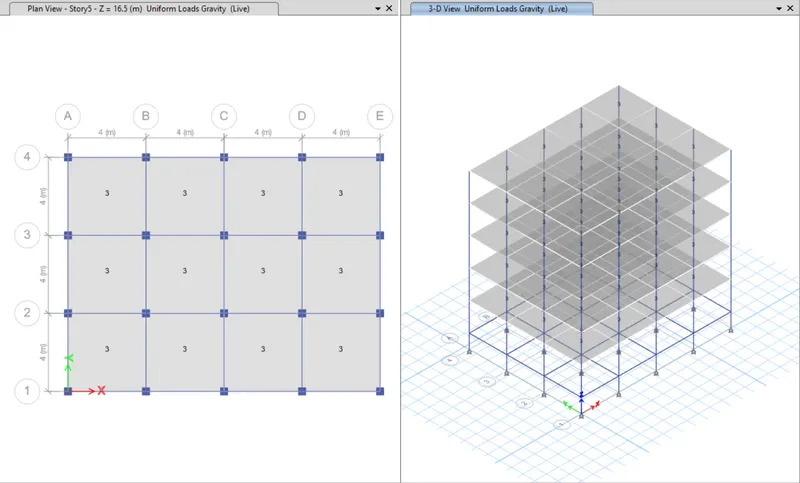
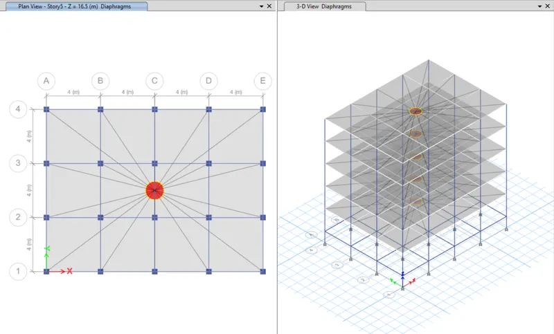
STEP 3: Check Loads
- Frame Loads
- Shell Loads
- Diaphragms
STEP 4: Run Analysis
- Click 'Run Analysis' from top menu
STEP 5: Model Tables
- From 'Model Explorer', select
- ANALYSIS RESULTS > Structure Output > Modal Information > Table: Modal Periods And Frequencies
- Right click and then click 'Show Table'
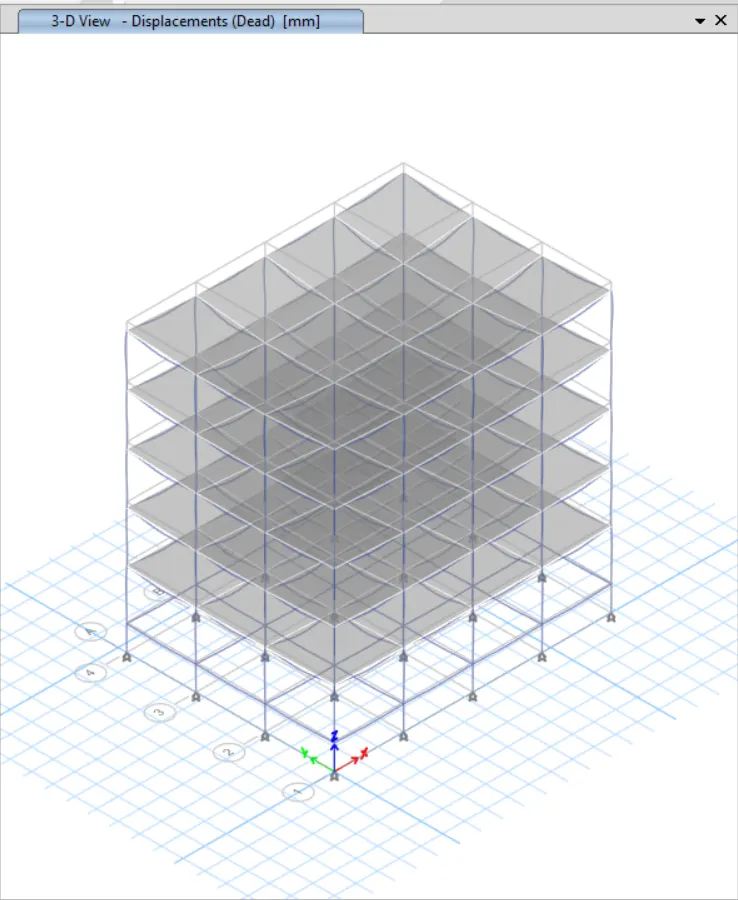
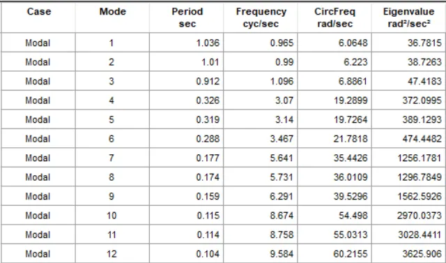
Model Response for Building B
Building C

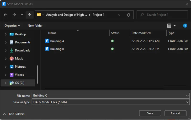
STEP 1: Save the Model
- Click 'Save As' under the 'File' tab
- Give file name as 'Building C' and click 'Save'
STEP 2: Edit Column Property
- Click 'Frame Section' in the 'Section Properties' under the 'Define' tab
- Click 'Modify/Show Property'
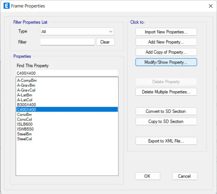
- Assign all options as given below
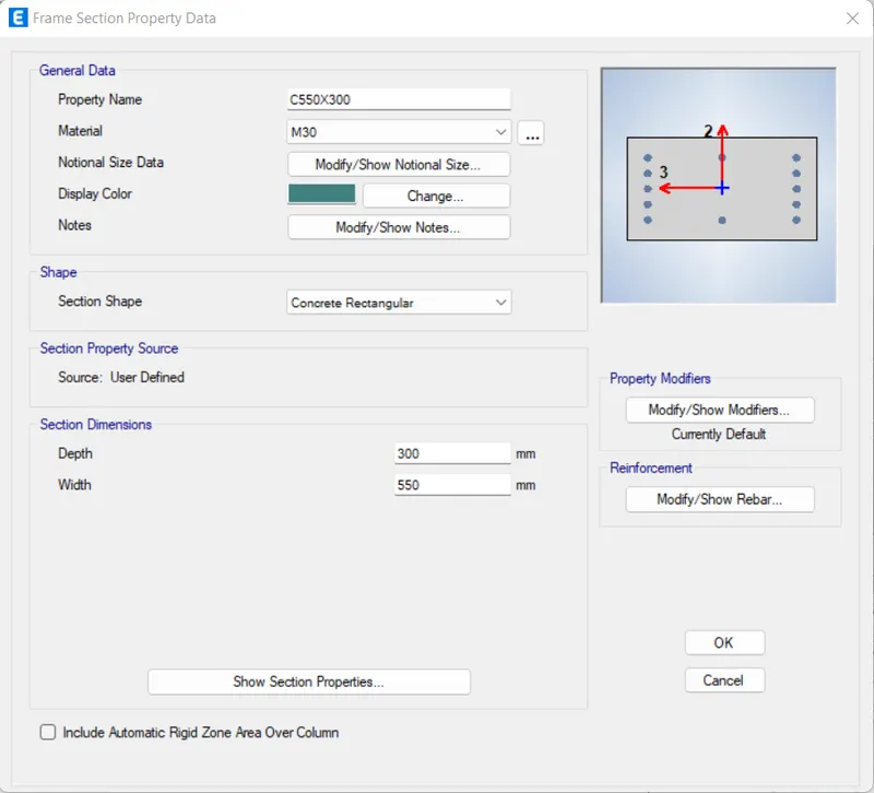
- Click 'OK'
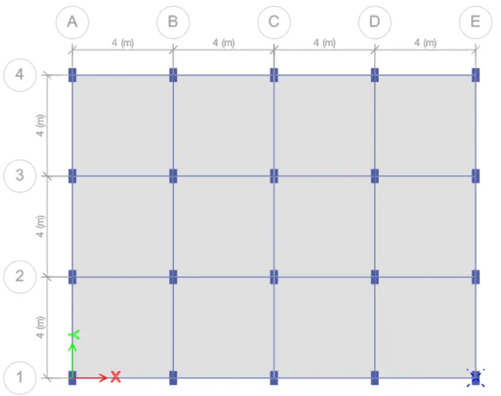
STEP 3: Rotate Column Axis
- Click 'Frame Sections' in the 'Properties' under the 'Select' tab
- Click 'C550X300' and click 'Select'
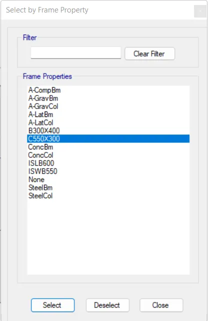
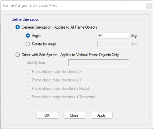
- Click 'Local Axes' in the 'Frame' under the 'Assign' tab
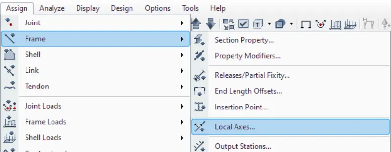
- Assign 'Angle' as '90' degree and click 'OK'
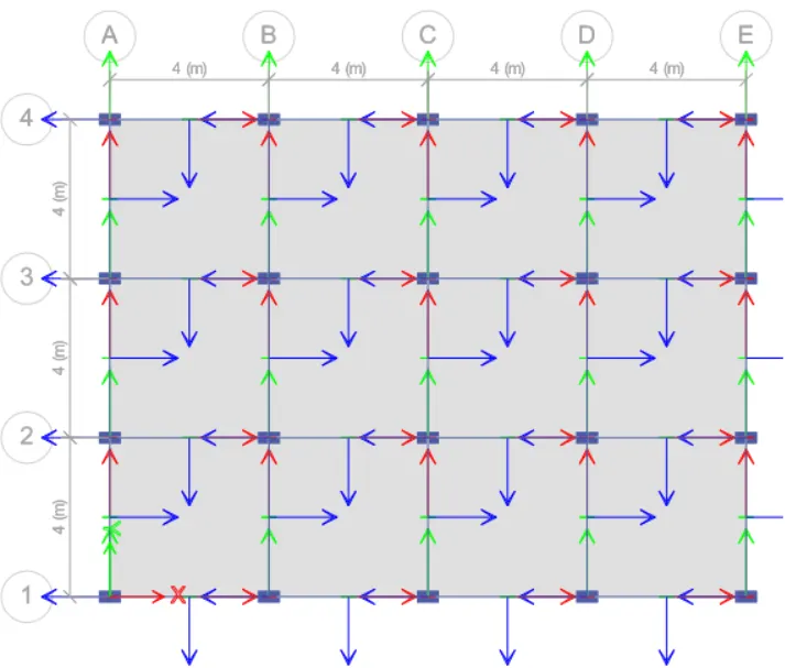
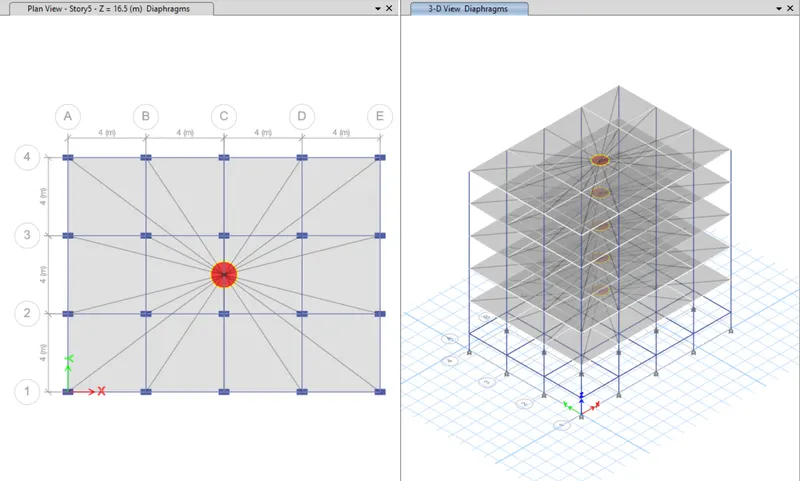
STEP 4: Check Loads
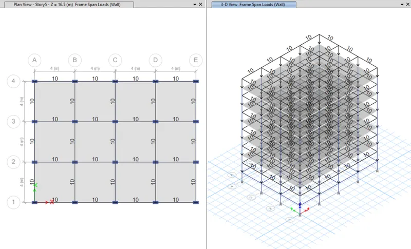
- Frame Loads
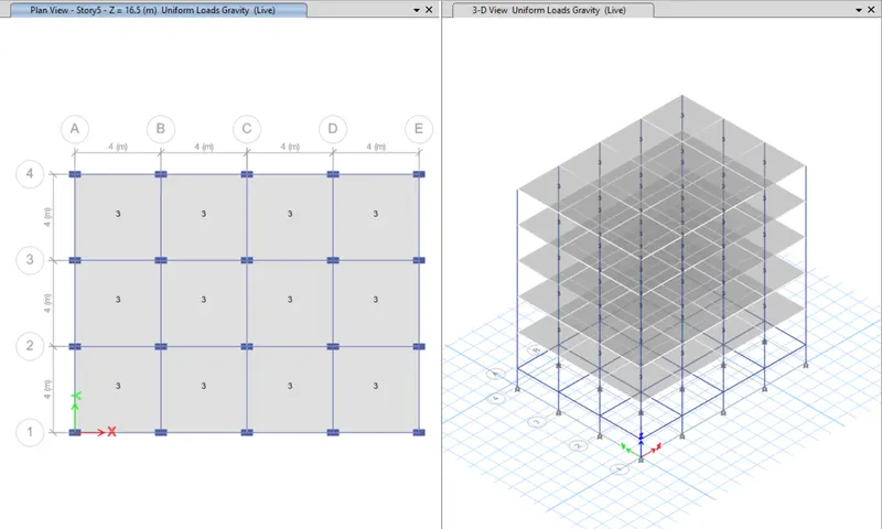
- Shell Loads
- Diaphragms
STEP 5: Run Analysis
- Click 'Run Analysis' from top menu
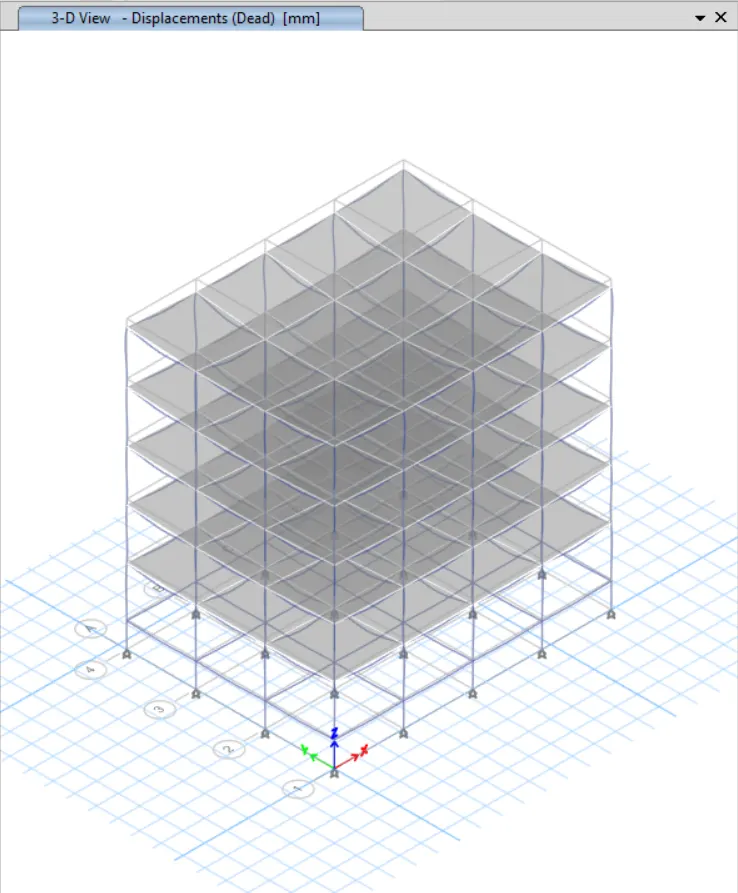
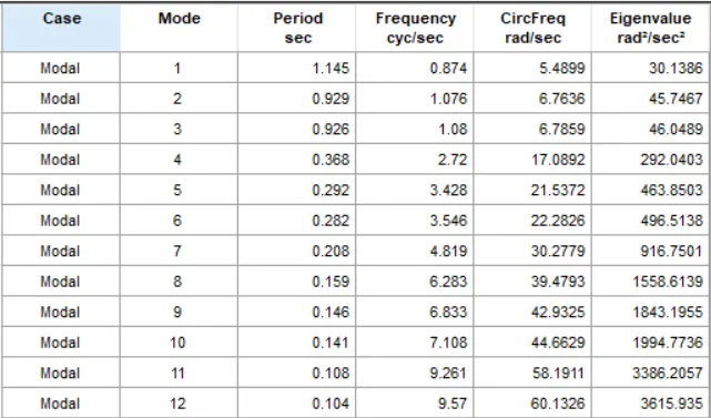
STEP 6: Model Tables
- From 'Model Explorer', select
- ANALYSIS RESULTS > Structure Output > Modal Information > Table: Modal Periods And Frequencies
- Right click and then click 'Show Table'
Model Response for Building C
Building D

STEP 1: Save the Model
- Click 'Save As' under the 'File' tab
- Give file name as 'Building D' and click 'Save'
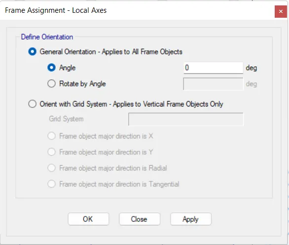
STEP 2: Rotate Column Axis
- Click 'Frame Sections' in the 'Properties' under the 'Select' tab
- Click 'C550X300' and click 'Select'
- Click 'Local Axes' in the 'Frame' under the 'Assign' tab
- Assign 'Angle' as '0' degree and click 'OK'
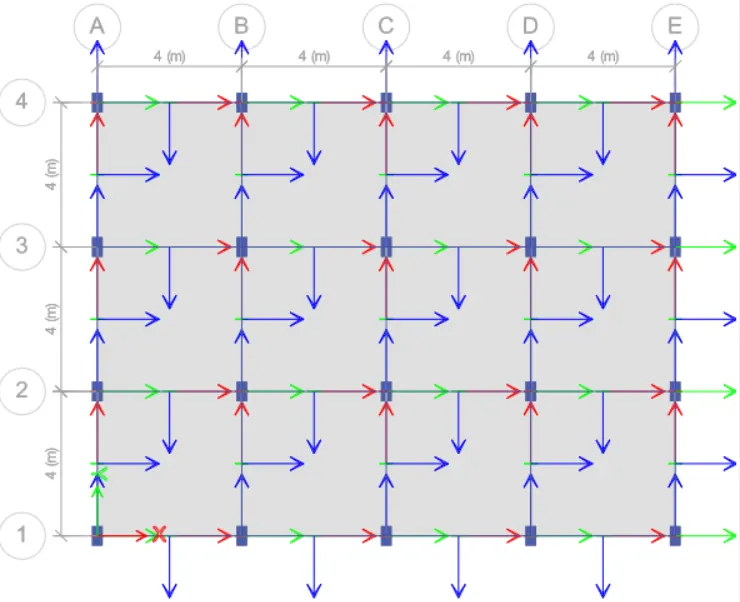
STEP 3: Check Loads
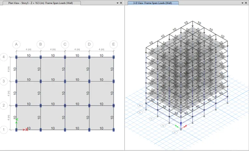
- Frame Loads
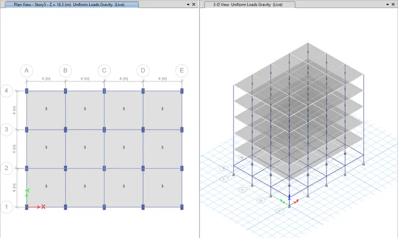
- Shell Loads
- Diaphragms
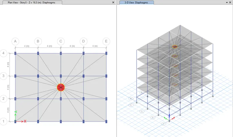
STEP 4: Run Analysis
- Click 'Run Analysis' from top menu
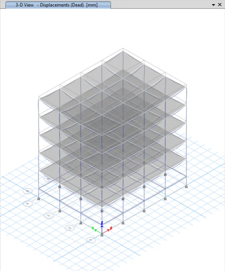
STEP 5: Model Tables
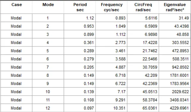
- From 'Model Explorer', select
- ANALYSIS RESULTS > Structure Output > Modal Information > Table: Modal Periods And Frequencies
- Right click and then click 'Show Table'
Model Response for Building D
Building E

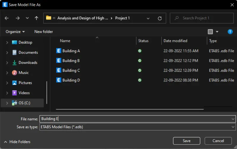
STEP 1: Save the Model
- Click 'Save As' under the 'File' tab
- Give file name as 'Building E' and click 'Save'
STEP 2: Add Stories
- Click 'Edit Stories and Grid Systems' under the 'Edit' tab
- Click 'Modify/Show Story Data'
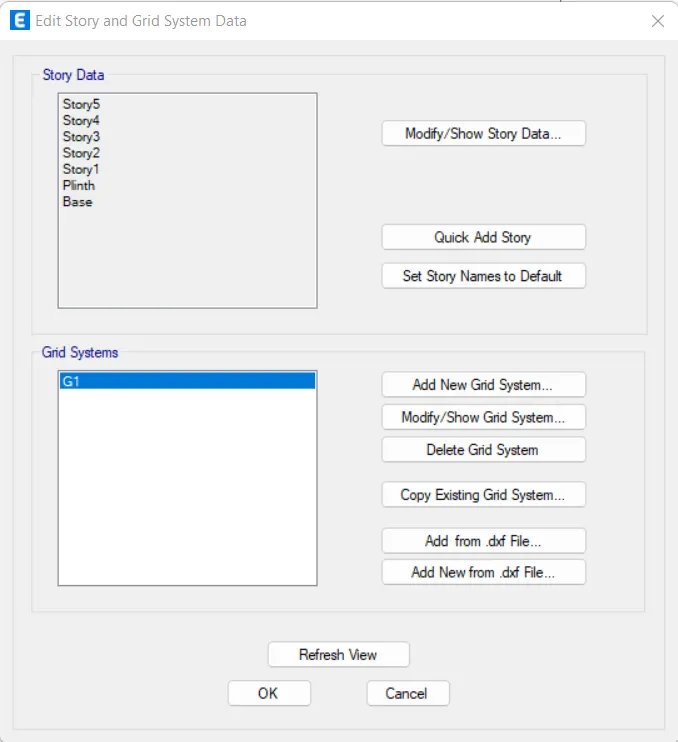
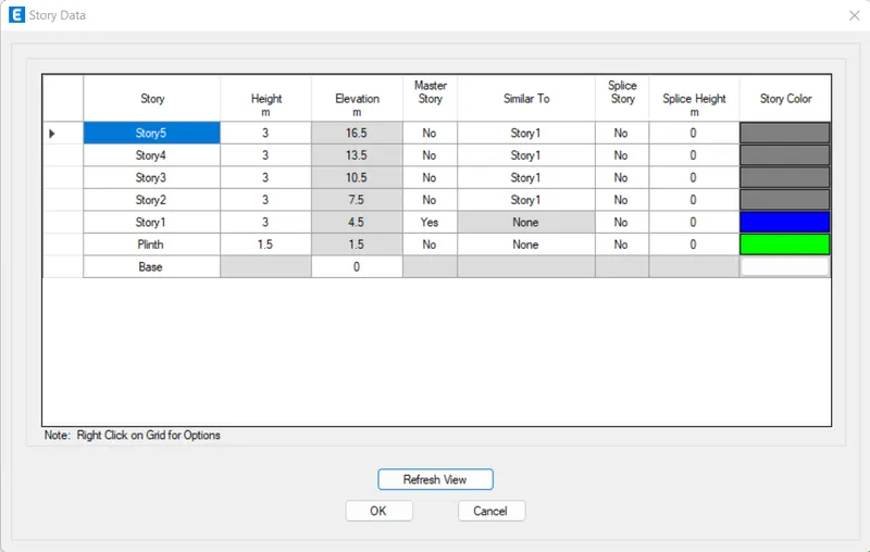
- Click 'Add Story' by right-clicking
- Assign 'Number of Added Stories' as '5'
- Click 'OK'
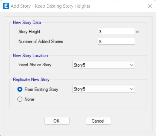
- Set 'Story1' as Master Story for 'Story6' to 'Story10'
- Click 'OK'
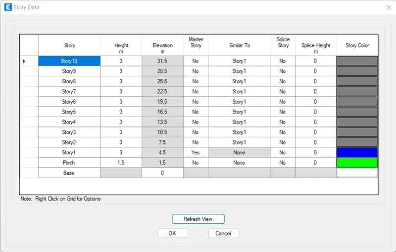
- Click 'OK'
STEP 3: Add Column Property
- Click 'Frame Section' in the 'Section Properties' under the 'Define' tab
- Click 'Add New Property'
- Assign all options as given below
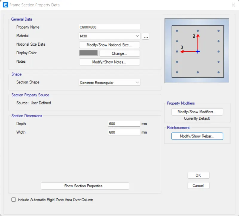
- Click 'Modify/Show Rebar'
- Assign all options as given below
- Click 'OK'
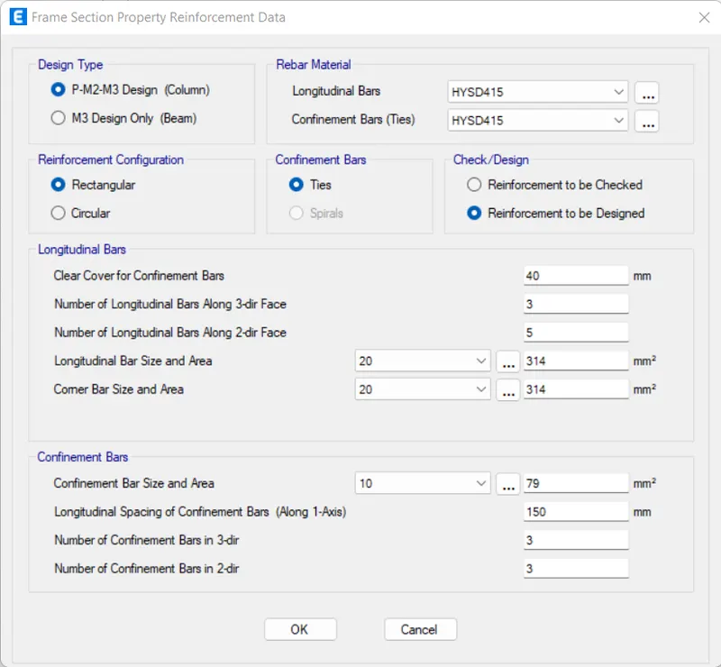
- Click 'OK'
- Again click 'Add New Property'
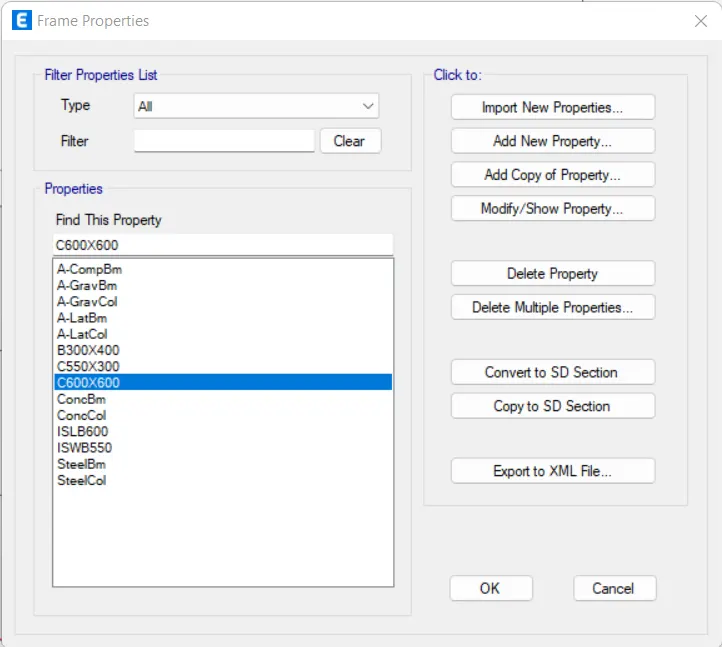
- Assign all options as given below
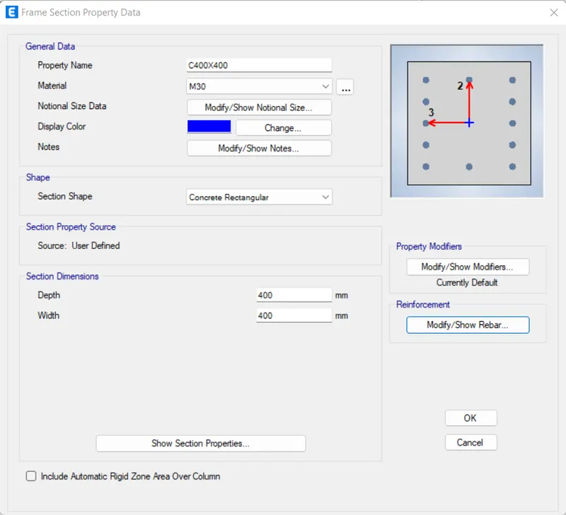
- Click 'Modify/Show Rebar'
- Assign all options as given below
- Click 'OK'
- Click 'OK'
STEP 4: Add Columns
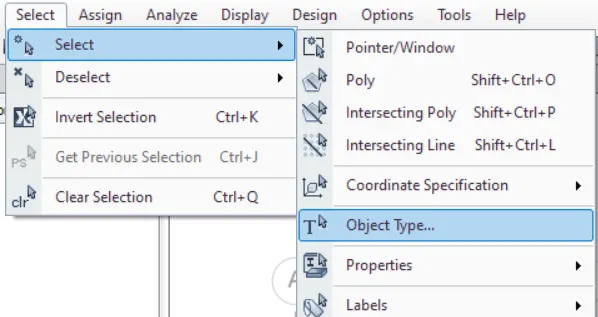
- Click 'Object Type' in the 'Select' tab
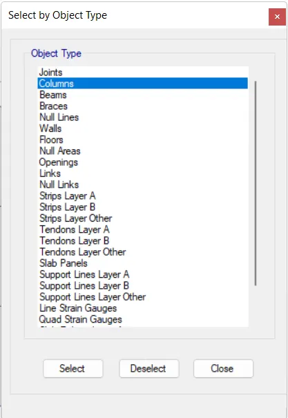
- Select 'Columns' and click 'Close'
- Press 'Delete'
- Then, click 'Quick Draw Columns' from the toolbars
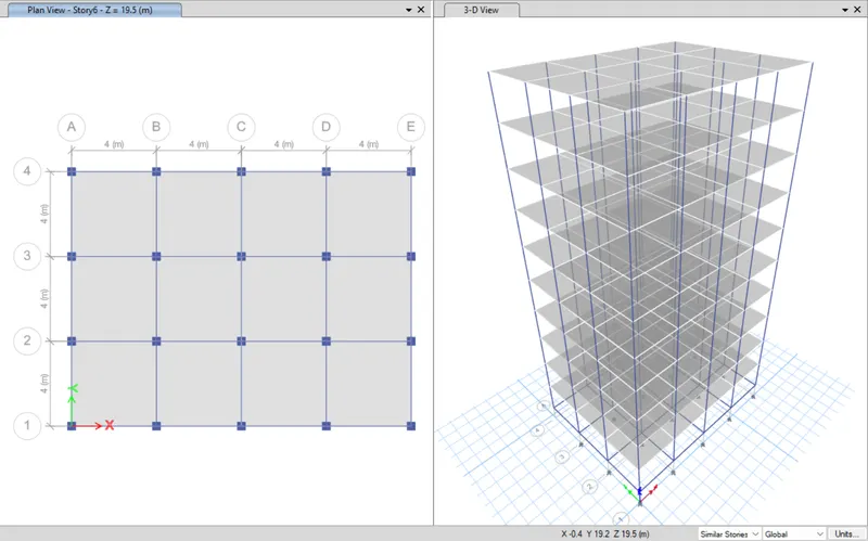
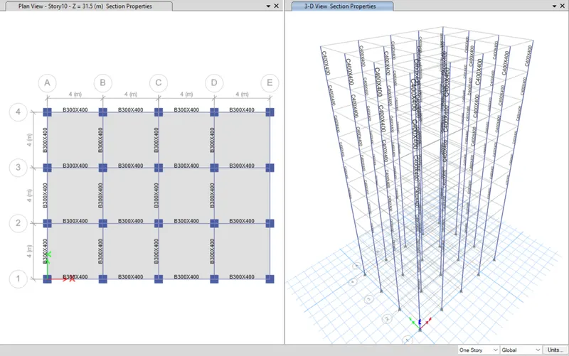
- Assign 'C600X600' as the property
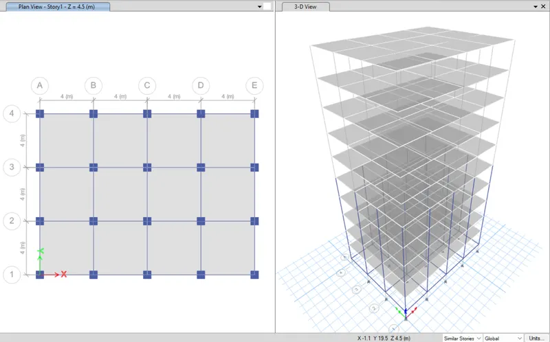
- Go to 'Story1' in the plan
- Select 'Similar Stories'
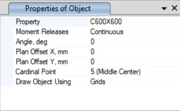
- Place the columns on grids
- Again, click 'Quick Draw Columns' from the toolbars
- Assign 'C400X400' as the property
- Go to 'Story6' in the plan
- Select 'Similar Stories'
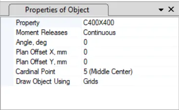
- Place the columns on grids
STEP 5: Check Loads
- Frame Loads
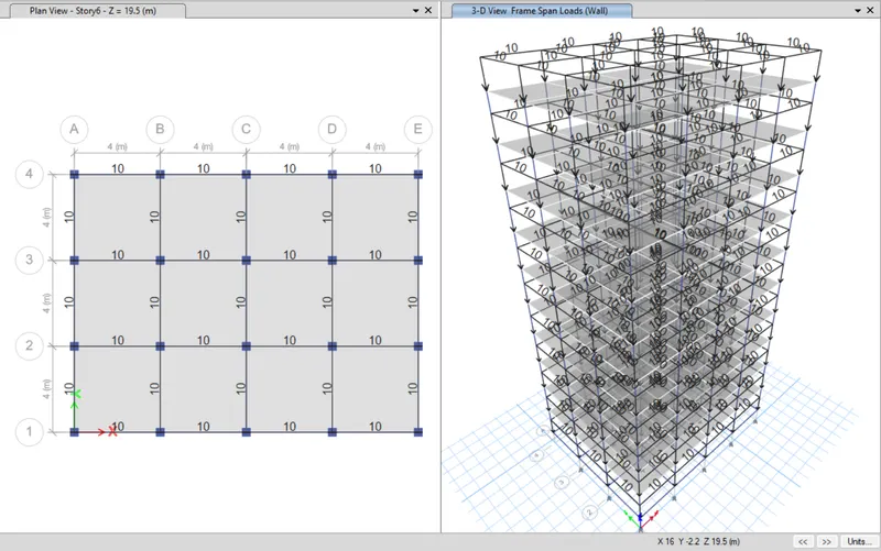
- Shell Loads
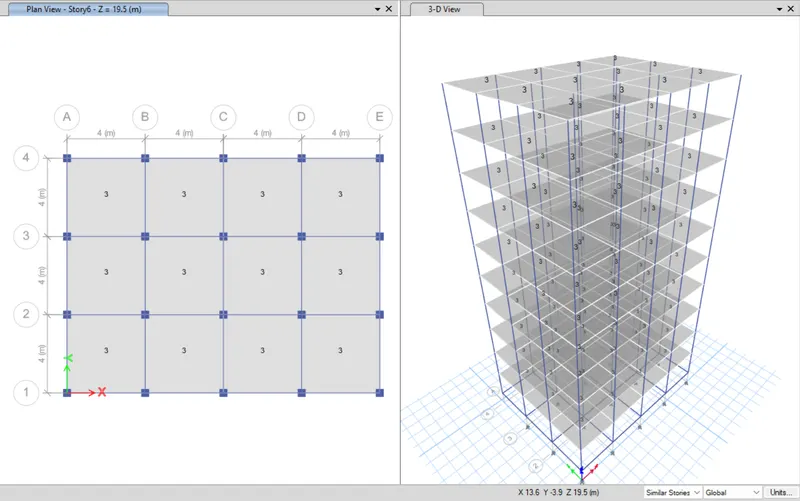
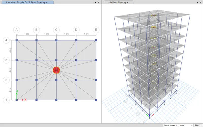
- Diaphragms
STEP 6: Run Analysis
- Click 'Run Analysis' from top menu
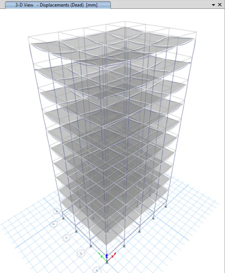
STEP 7: Model Tables
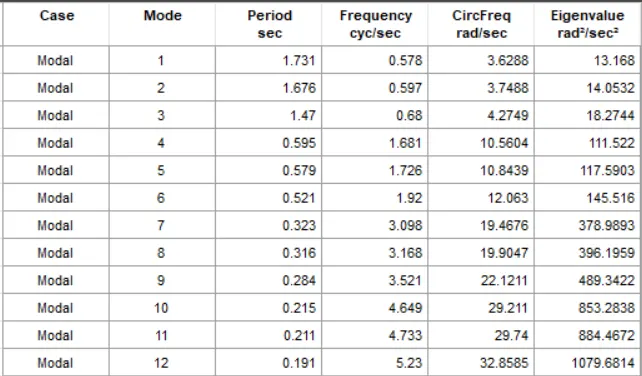
- From 'Model Explorer', select
- ANALYSIS RESULTS > Structure Output > Modal Information > Table: Modal Periods And Frequencies
- Right click and then click 'Show Table'
Model Response for Building E
Building F

STEP 1: Save the Model
- Click 'Save As' under the 'File' tab
- Give file name as 'Building F' and click 'Save'
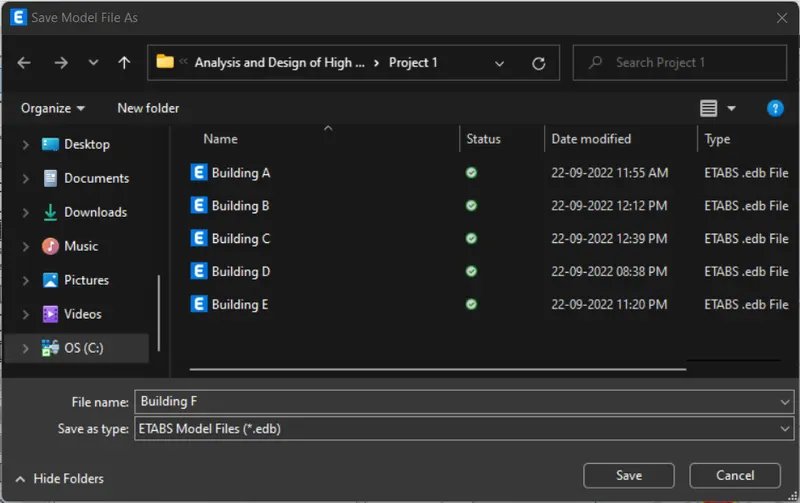
STEP 2: Column Change
- Press 'ctrl+w' to get 'Set View Options'
- Uncheck 'Beams' and 'Floors'
- Click 'OK'
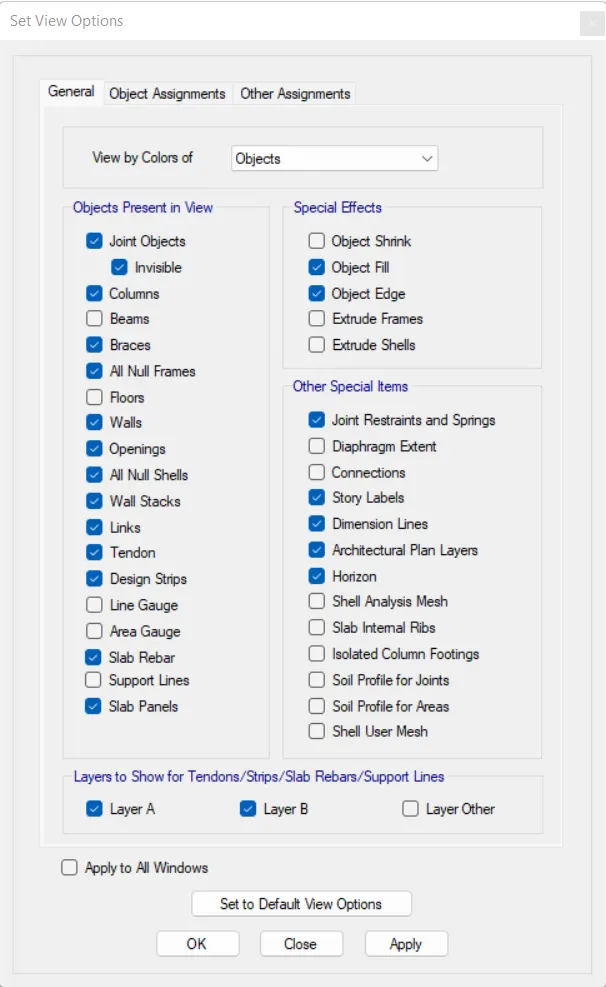
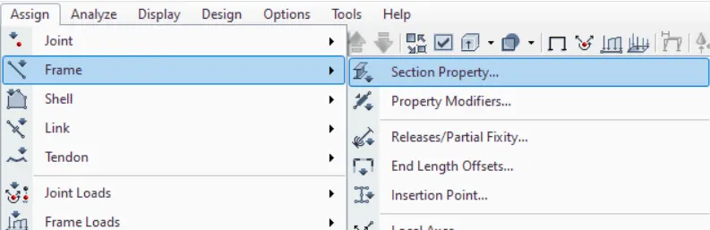
- Select all the columns
- Click 'Section Property' in the 'Frame' under the 'Assign' tab
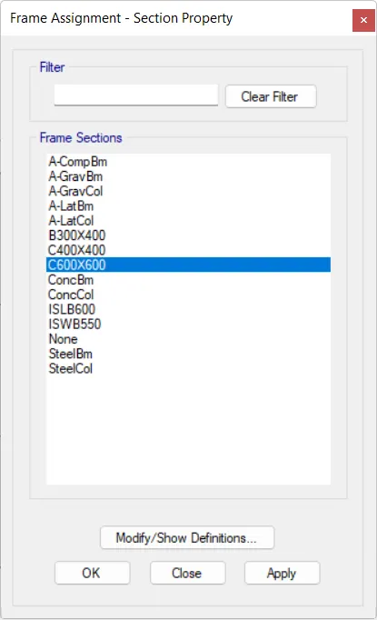
- Select 'C600X600' and click 'OK'
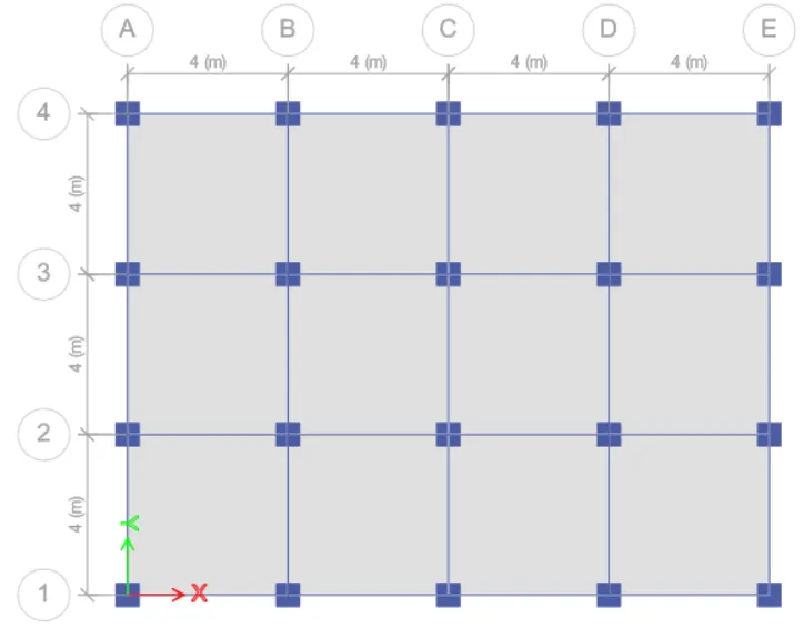
STEP 3: Check Loads
- Frame Loads
- Shell Loads
- Diaphragms
STEP 4: Run Analysis
- Click 'Run Analysis' from top menu
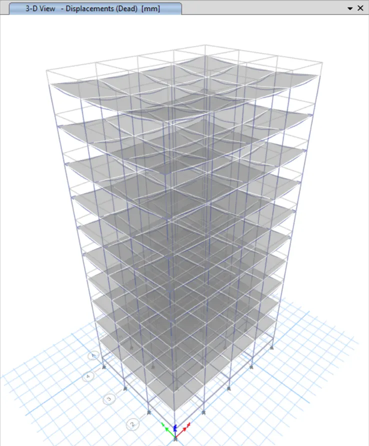
STEP 5: Model Tables
- From 'Model Explorer', select
- ANALYSIS RESULTS > Structure Output > Modal Information > Table: Modal Periods And Frequencies
- Right click and then click 'Show Table'
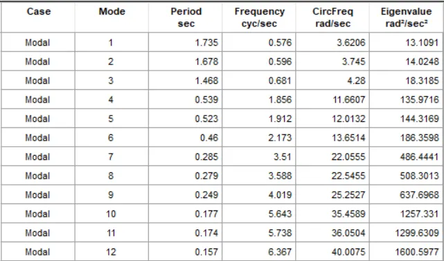
Model Response for Building F
Building G

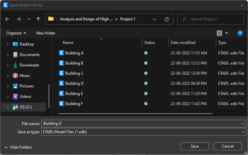
STEP 1: Save the Model
- Click 'Save As' under the 'File' tab
- Give file name as 'Building G' and click 'Save'
STEP 2: Add Stories
- Click 'Edit Stories and Grid Systems' under the 'Edit' tab
- Click 'Modify/Show Story Data'
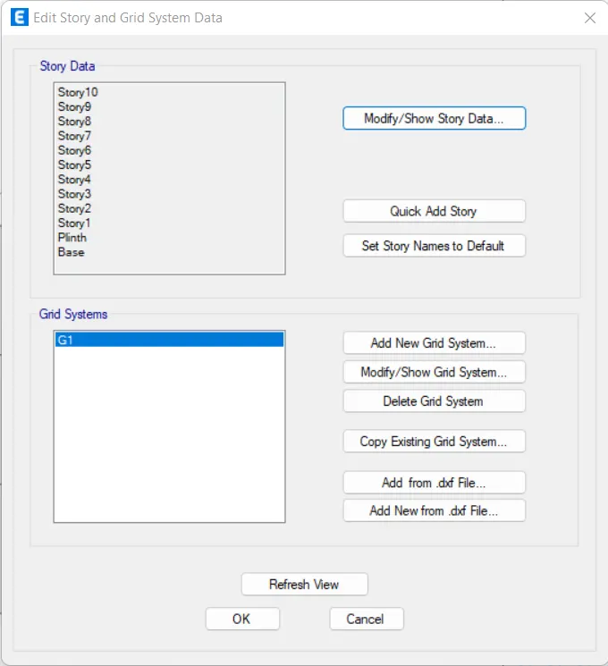
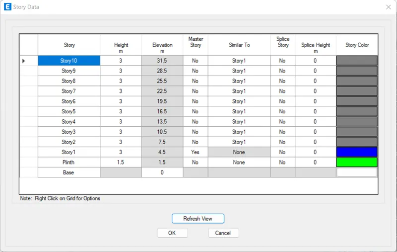
- Click 'Add Story' by right-clicking
- Assign 'Number of Added Stories' as '15'
- Click 'OK'
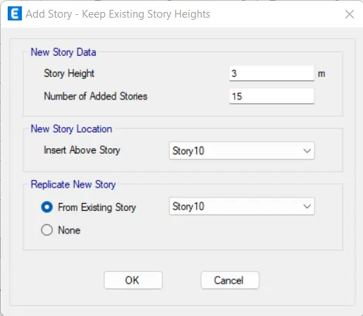
- Set 'Story1' as Master Story for 'Story11' to 'Story25'
- Click 'OK'

- Click 'OK'
STEP 3: Add Column Properties
- Click 'Frame Section' in the 'Section Properties' under the 'Define' tab
- Click 'Add New Property'
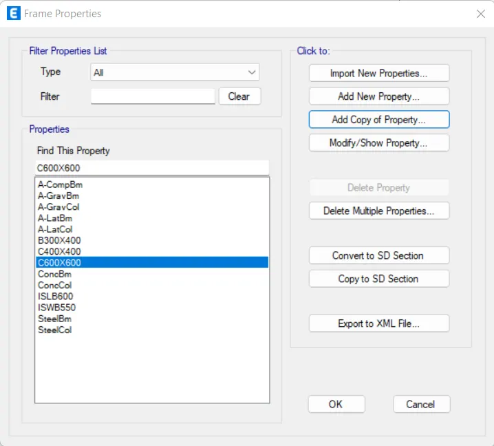
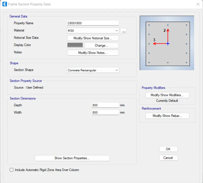
- Click 'Rectangular Section'
- Assign all options as given below
- Click 'Modify/Show Rebar'
- Assign all options as given below
- Click 'OK'
- Click 'OK'
STEP 4: Column Change
- Press 'ctrl+w' to get 'Set View Options'
- Uncheck 'Beams' and 'Floors'
- Click 'OK'
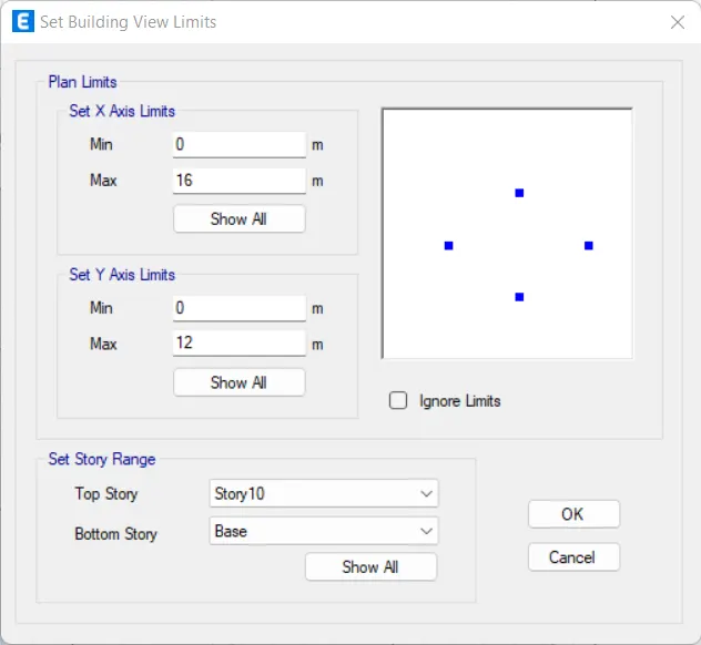
- Click 'Set Building View Limits' under the 'View' tab
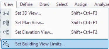
- Assign top story as 'Story10' and bottom story as 'Base'
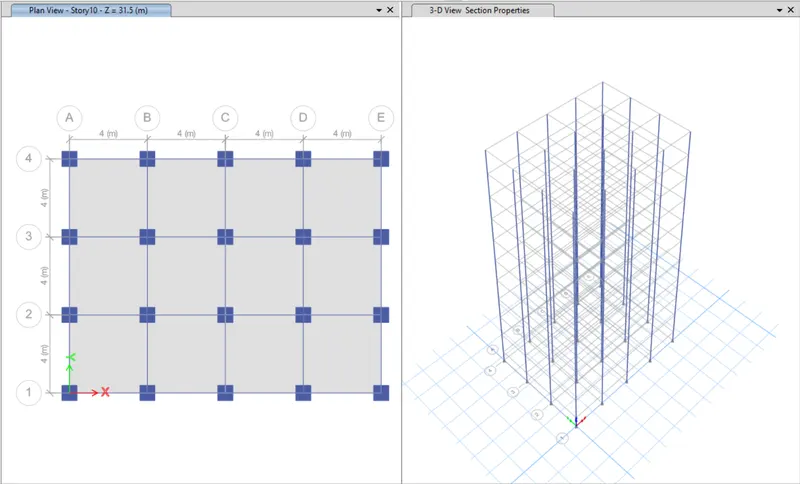
- Select all the columns
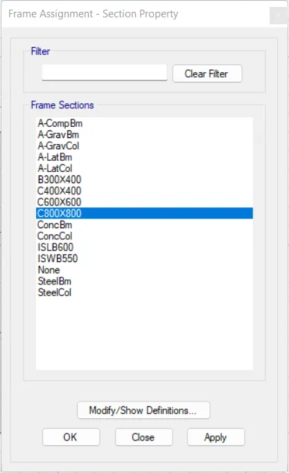
- Click 'Section Property' in the 'Frame' under the 'Assign' tab
- Select 'C800X800' and click 'OK'
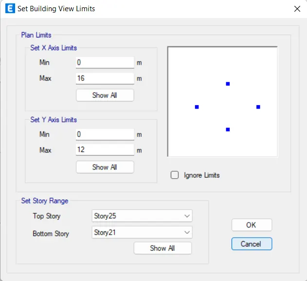
- Again, click 'Set Building View Limits' under the 'View' tab
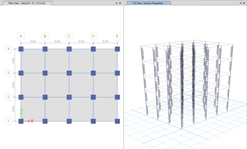
- Assign top story as 'Story25' and bottom story as 'Story21'
- Select all the columns
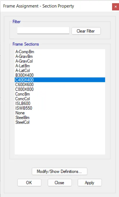
- Click 'Section Property' in the 'Frame' under the 'Assign' tab
- Select 'C400X400' and click 'OK'
STEP 5: Check Loads
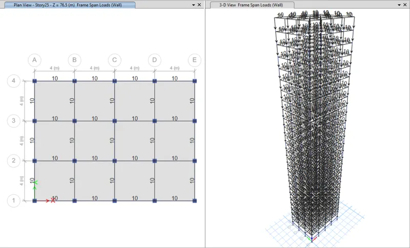
- Frame Loads
- Shell Loads
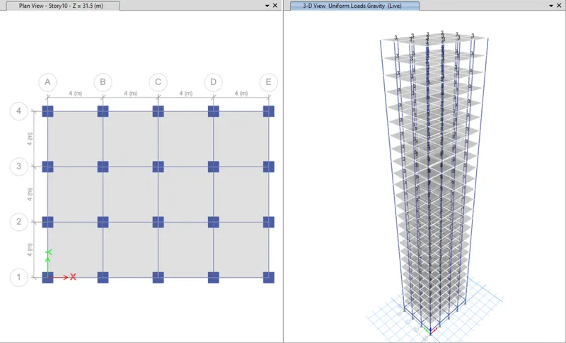
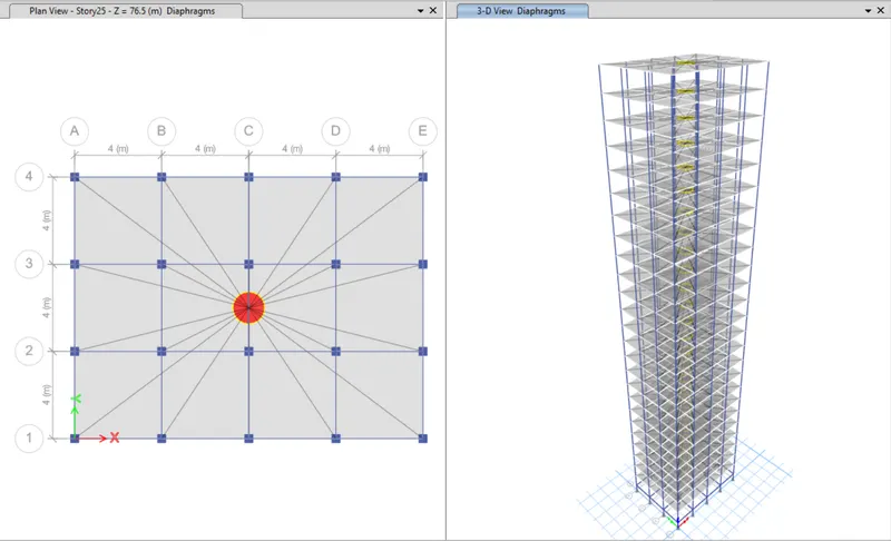
- Diaphragms
STEP 6: Run Analysis
- Click 'Run Analysis' from top menu
STEP 7: Model Tables
- From 'Model Explorer', select
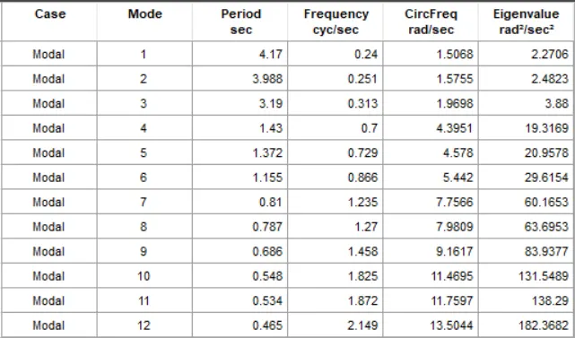
- ANALYSIS RESULTS > Structure Output > Modal Information > Table: Modal Periods And Frequencies
- Right click and then click 'Show Table'
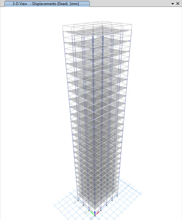
Model Response for Building G
Building H

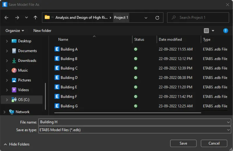
STEP 1: Save the Model
- Click 'Save As' under the 'File' tab
- Give file name as 'Building H' and click 'Save'
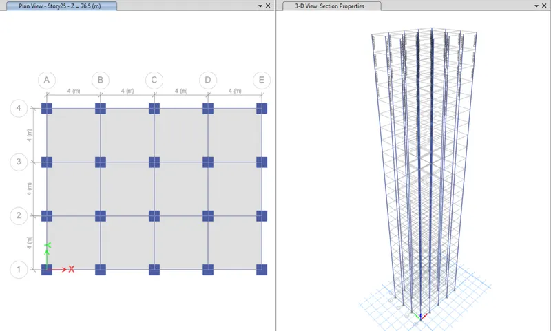
STEP 2: Column Change
- Press 'ctrl+w' to get 'Set View Options'
- Uncheck 'Beams' and 'Floors'
- Click 'OK'
- Select all the columns
- Click 'Section Property' in the 'Frame' under the 'Assign' tab
- Select 'C800X800' and click 'OK'
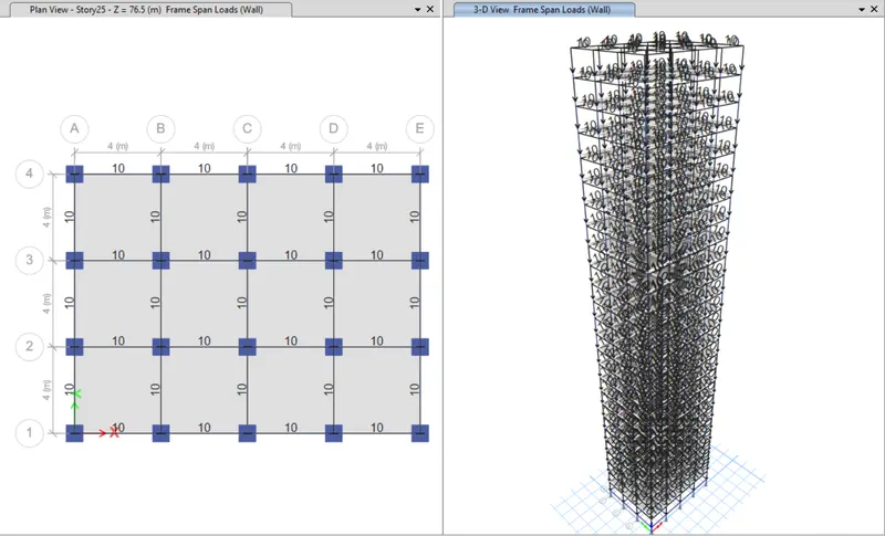
STEP 3: Check Loads
- Frame Loads
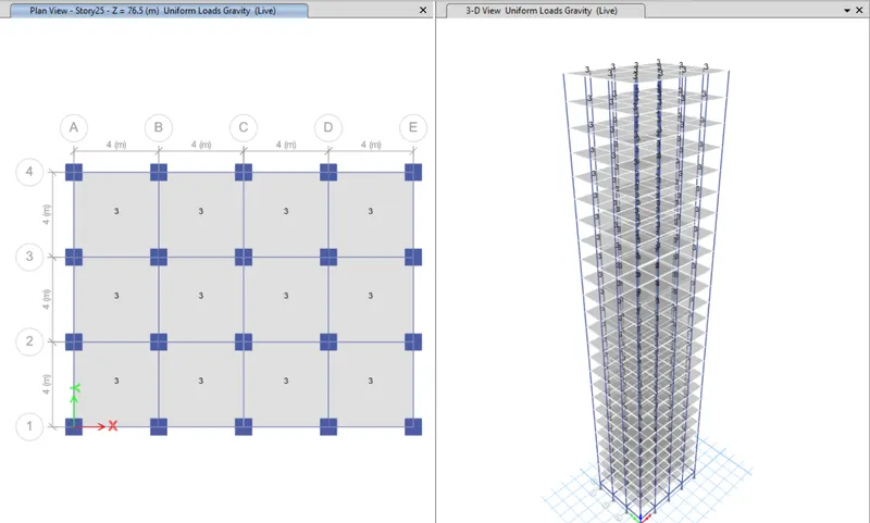
- Shell Loads
- Diaphragms
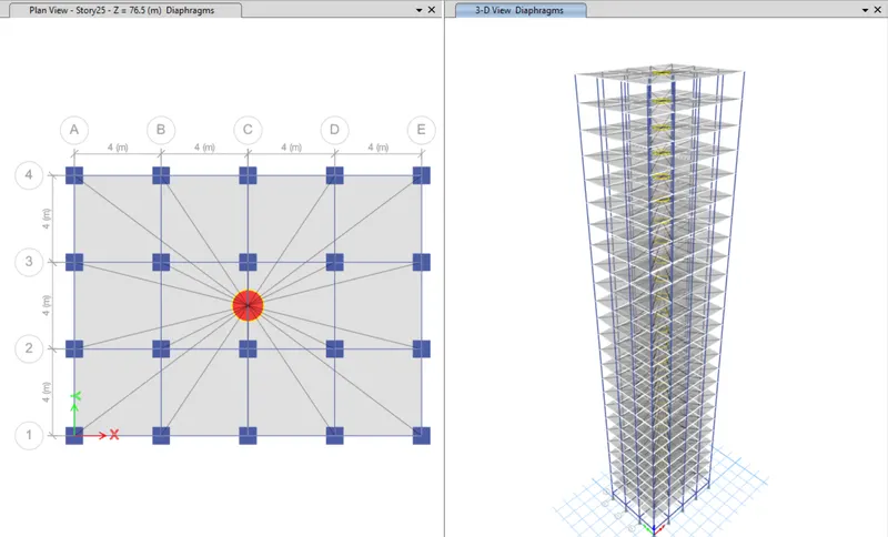
STEP 4: Run Analysis
- Click 'Run Analysis' from top menu
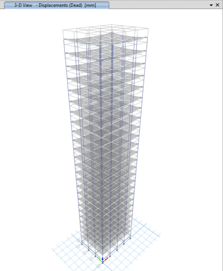
STEP 5: Model Tables
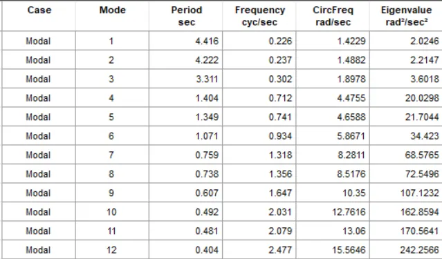
- From 'Model Explorer', select
- ANALYSIS RESULTS > Structure Output > Modal Information > Table: Modal Periods And Frequencies
- Right click and then click 'Show Table'
Model Response for Building H
Building J

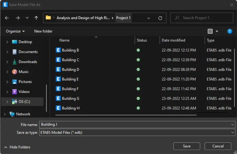
STEP 1: Save the Model
- Click 'Save As' under the 'File' tab
- Give file name as 'Building J' and click 'Save'
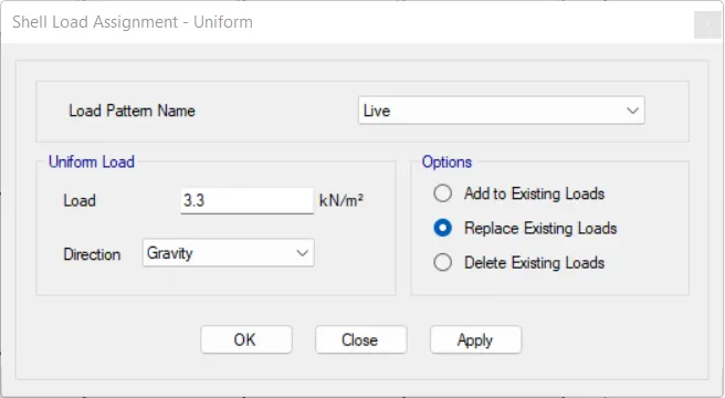
STEP 2: Assign Loads
- Click 'Slab Sections' in the 'Properties' under the 'Select' tab
- Click 'S150' and click 'Select'
- Click 'Uniform' in the 'Shell Loads' under the 'Assign' tab
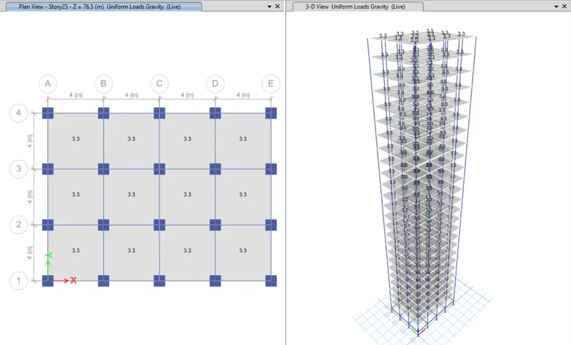
- Assign 'Live' load as 3.3KN/m2 as shown below
- Click 'Apply'
STEP 3: Run Analysis
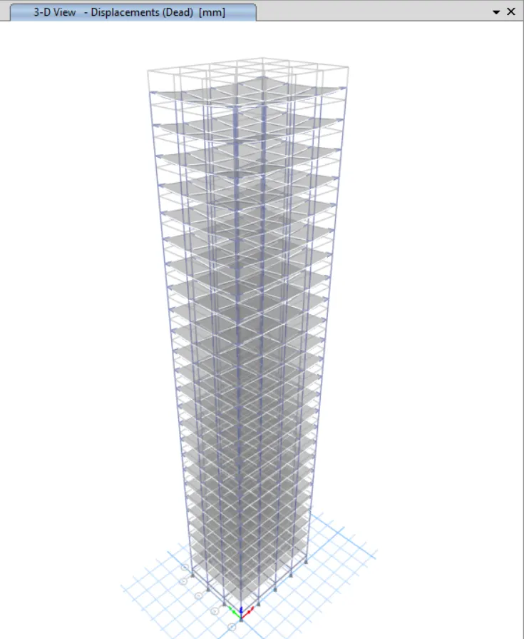
- Click 'Run Analysis' from top menu
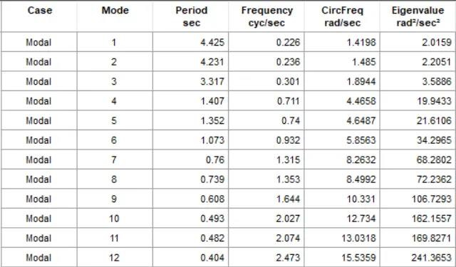
STEP 4: Model Tables
- From 'Model Explorer', select
- ANALYSIS RESULTS > Structure Output > Modal Information > Table: Modal Periods And Frequencies
- Right click and then click 'Show Table'
Model Response for Building J
Building K

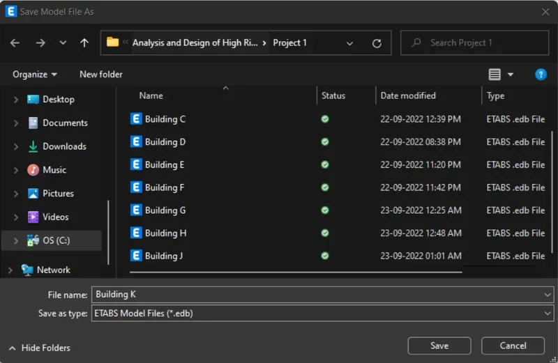
STEP 1: Save the Model
- Click 'Save As' under the 'File' tab
- Give file name as 'Building K' and click 'Save'
STEP 2: Assign Loads
- Click 'Slab Sections' in the 'Properties' under the 'Select' tab
- Click 'S150' and click 'Select'
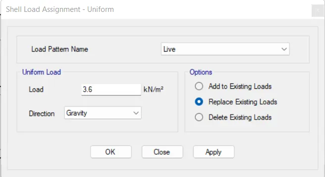
- Click 'Uniform' in the 'Shell Loads' under the 'Assign' tab
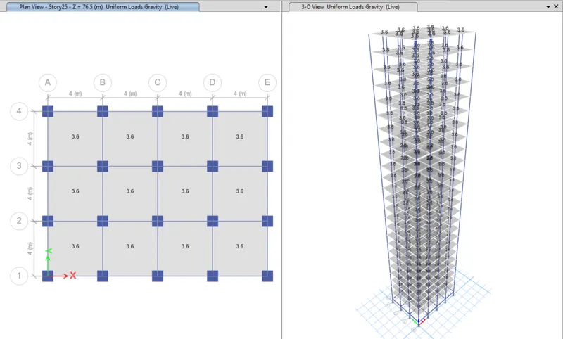
- Assign 'Live' load as 3.6KN/m2 as shown below
- Click 'Apply'
STEP 3: Run Analysis
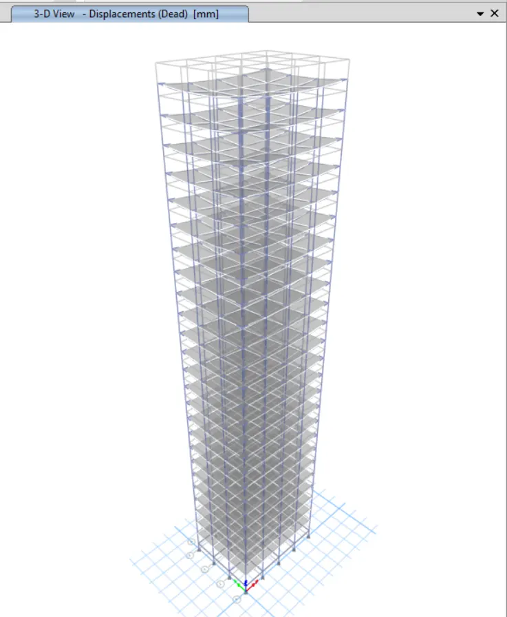
- Click 'Run Analysis' from top menu
STEP 4: Model Tables
- From 'Model Explorer', select
- ANALYSIS RESULTS > Structure Output > Modal Information > Table: Modal Periods And Frequencies
- Right click and then click 'Show Table'
Model Response for Building K
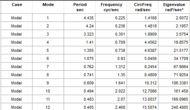
RESULTS
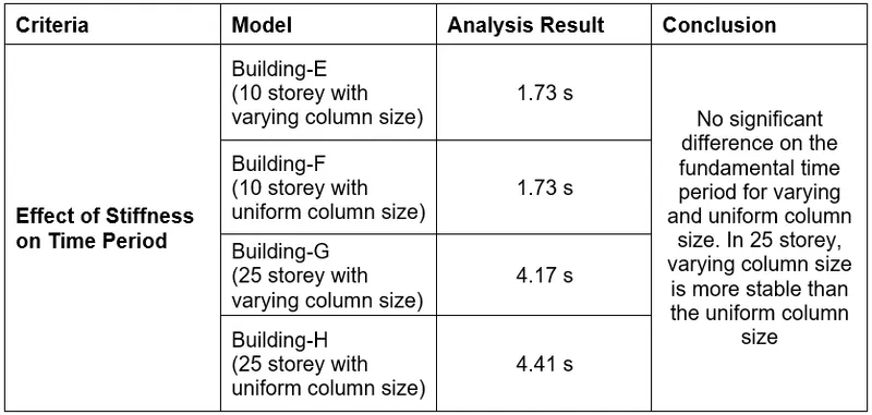
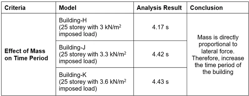
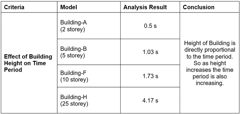
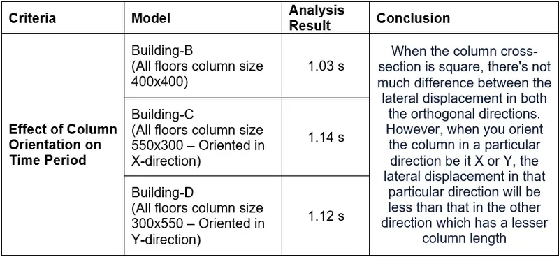
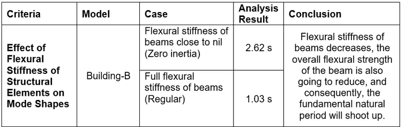
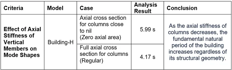
10 buildings of different stories are modeled for Seismic force for a comparative study. The tables needed to obtain result for the checks are given in the procedure. The comparative study is shown in the table below.
1. Effect of Stiffness on Time Period
2. Effect of Mass on Time Period
3. Effect of Building Height on Time Period
4. Effect of Column Orientation on Time Period
5. Effect of Flexural Stiffness of Structural Elements on Mode Shapes
6. Effect of Axial Stiffness of Vertical Members on Mode Shapes
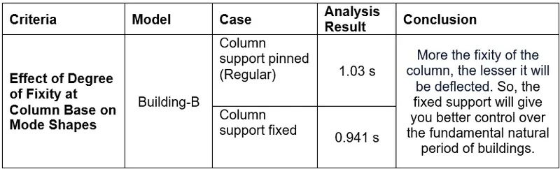
7. Effect of Degree of Fixity at Column Base on Mode Shapes