Project 1_Comparative study of different storey buildings for Seismic forces
Aim:
To compare fundamental natural peroids of building H,J and K using ETABS
Procedure:
Step 1
Go to the Etabs application
select the new model
Step 2
select the model intialization
select the use built in setting with
write the following table
Step 3
select the new model quick template
select the custom grid spacing
each grids at 5 column
each grids at 4 rows
Step 4
select the custom story data
add the story at 25
select the base,plinth and values at 3m and 1.5m
Step 5
select the define tools
select the material property
add the material
select the region,grade
Step 6
select the define tools
select the material property
add the material
select the region,rebar
Step 7
select the define tools
select the section property
select the frame properties
add the material
select the concrete
select the beam 300X400mm
Step 8
select the define tools
select the section property
select the frame properties
add the material
select the concrete
select the column 800X800mm
Step 9
select the define tools
select the section propertyselect the slab peoperties
add the material
select the slab 150mm
Step 10
select the define tools
select the load pattern
add the material
select the dead load,live load,wall,EQX,EQY
select the codes IS1893:2016
Step 11
select the define tools
select the mass source
select the modifie the mass souce
select only the specificed load patterns
Step 12
select the define tools
select the load cases
select the ok button
Step 13
select the load combination
add the default design combination
select the concrete frame design
select the ok button
Building A:
Step 1
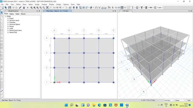
click the edit tab and choose edit story
add 2 story and make 1st story as master and all other as similar to 1st story
click ok
Step 2
click the select tab and select the columns
click assign tab and choosen frame assignment as 400x400 dimension column
click ok
Step 3
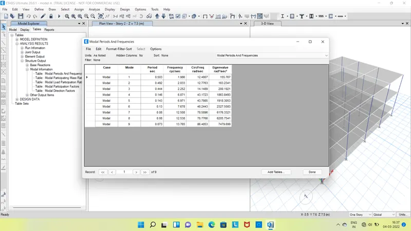
after assigning loads of each frame run the analysis
click display and choose the show table option
select modal participating ratio from srtuctural output
click ok
Building B:
Step 1
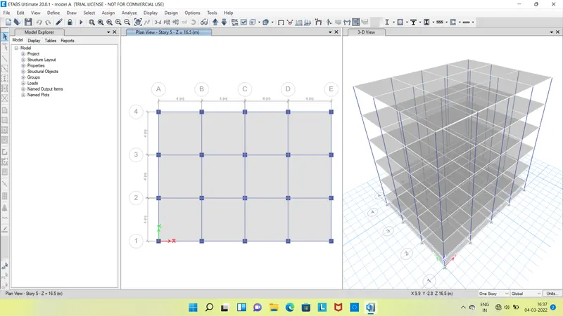
click the edit tab and choosen edit story
add 5 story and make 1st story as master and all other as similar to 1st story
click ok
Step 2
click the select tab and select the column
click assign tab and choose frame assignment as 400x400 dimension column
click ok
Step 3
click the select tab and assign the column dimension as 400x400
click the select tab and choose floors
click assign tab and choose shell loads then uniform load
make live load and load patten name and input 3kn/sq.m for load value and brick wall load as 10kn/sq.m
Step 4
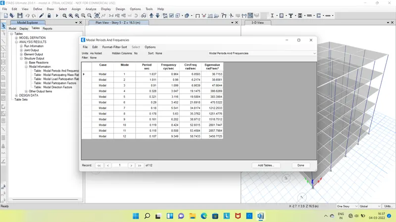
after assigning loads of each frame run the analysis
click display and choose the show table option
select modal participating ratio from structural output
click ok
Building C:
Step 1
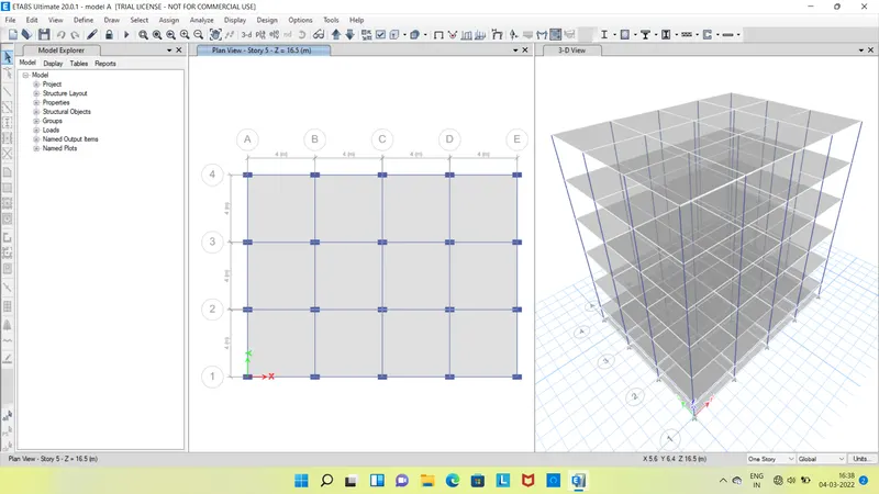
click the select tab and select the column
click assign tab and choosen frame assignment as 550x300 dimension column
click ok
Step 2
select the column object
click the assign tab and choosen frame section then local axes
select rotation angle and enter the degree of 90
click ok
Step 3
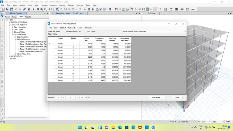
after assigning loads of each frame run the analysis
click display and choosen show table option
select modal participating ratio from structural output
click ok
Building D:
Step 1
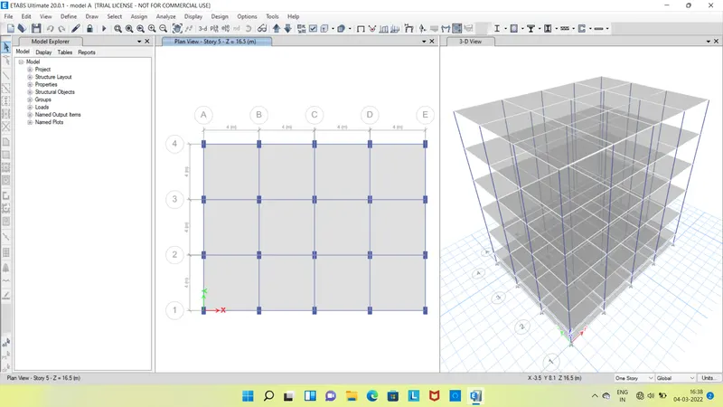
click the select tab and select the columns
click assign tab and choose frame assignment as 300x550 dimension column
click ok
Step 2
select the column object
click the assign tab and choose frame sections then local axes
select rotation angle and enter the degree of 0
click ok
Step 3
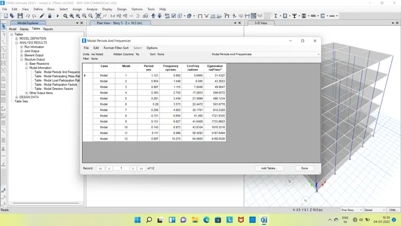
after assigning loads of each frame run the analysis
click display and choose the show table option
select modal participating ratio from structural output
click ok
Building E:
Step 1
click the edit tab and choose edit story
add 10story and make 1st story as master and all other as smiliar to 1st story
click ok
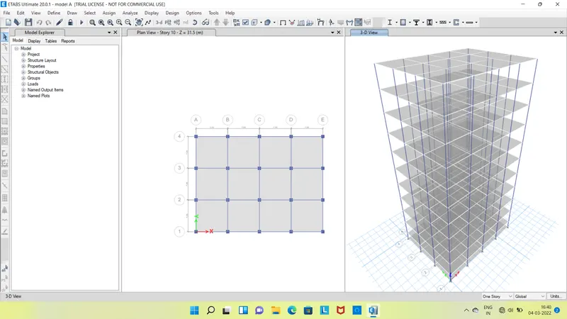
Step 2
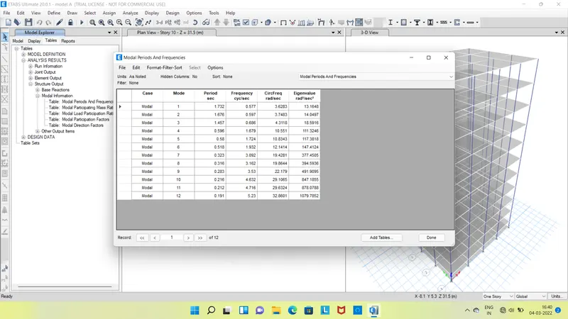
after assigning loads of each frame run the analysis
click display and choose the show table option
select modal participating ratio from structural output
click ok
Building F:
Step 1
click the select tab and select the columns
click assign tab and choose frame assignment as 600x600 dimension column
click ok
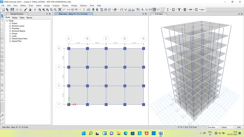
Step 2
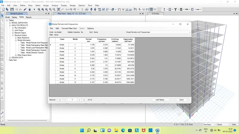
after assigning the loads of each frame run the analysis
click display and choose show table option
select modal participating ratio from structural output
click ok
Building G:
Step 1
click the edit tab and choose edit story
add 25 story and make 1st storyb11th story and 21st story as master and all other as smiliar to 1st ,11th,21st story
click ok
Step 2
click the select tab and select the columns of the 11th story
click assign tab and choose frame assignment as 600x600 dimension column
click ok
Step 3
click the select tab and select the columns of 21st story
click assign tab and choosen frame assignment as 400x400 dimension column
click ok
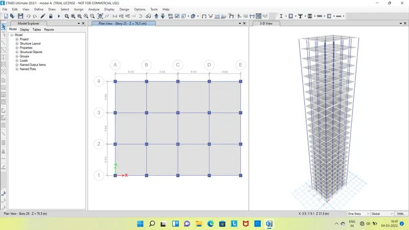
Step 4
Click select tab and select the columns
click assign tab and choose frame assignment as 400x400 dimension column
click ok
Step 5
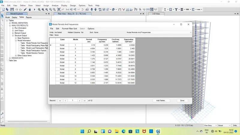
after assigning loads of each frame run the analysis
click display and choose the show table option
select modal participating ratio from structural output
click ok
Building H:
Step 1
click the define tab and click section section properties
select add new property and choose rectangular
add the new column dimension 800x800
click ok
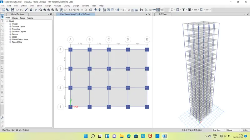
Step 2
Click select tab and select the columns
click assign tab and choose frame assignment as 800x800 dimension column
click ok
Step 3
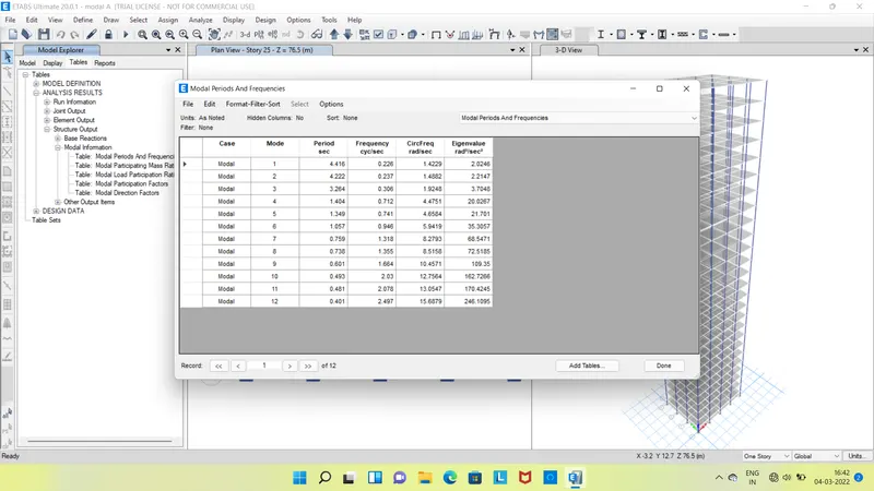
after assigning loads of each frame run the analysis
click display and choose the show table option
select modal participating ratio from structural output
click ok
Building J:
Step 1
click the edit tab and choose edit story
add 25 story and make 1st story as master and all other as similar to 1st story
click ok
Step 2
click the select tab and select the columns
click assign tab and choose frame assignment as 800x800 dimension column
click ok
Step 3
click the select tab and assign the column dimensions as 800x800
click the select tab and choosen floors
click assign tab and choosen shell loads then uniform load
make live load and load pattern name and input 3kn/sq.m for load value
click ok
Step 4
click the select tab and choose beams
clock assign tab and choose frame loads then distribute
make brick wall loads as input 10kn/sq.m for load value
click ok
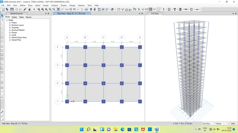
step 5
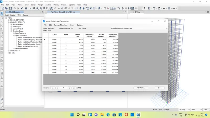
after assigning loads of each frame run the analysis
click display and choose the show table option
select modal participating ratio from structural output
click ok
Building K:
Step 1
click the select tab and assign the column dimension as 800x800
click the select tab and choose floors
click assign tab and choose shell loads then uniform load
make live load and load pattern name cand input 60kn/sq.m for load value
click ok
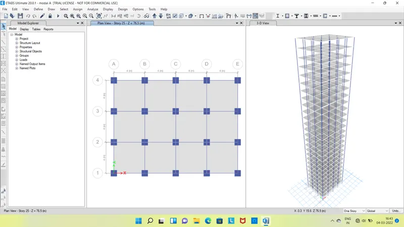
Step 2
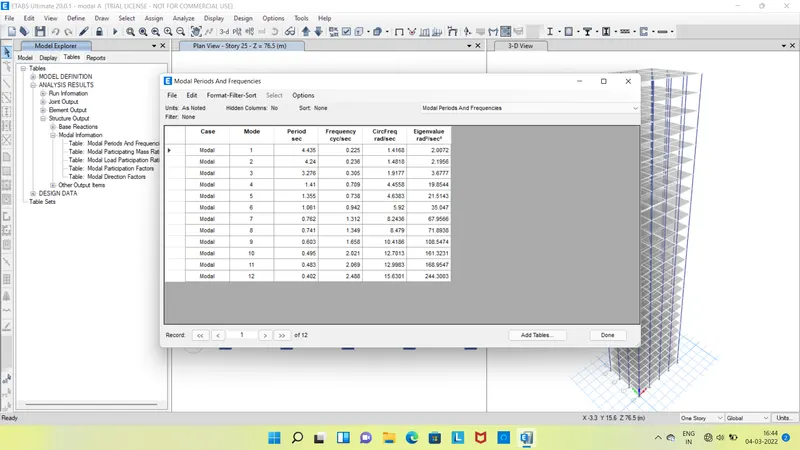
after assigning loads of each frame run the analysis
click display and choose the show table option
select modal participating ratio from structural output
click ok
Conculsion:
Effect of stiffness on T:
| Criteria | Model | Result |
| effect of stiffness on time period | Building E | 1.73 s |
| Building F | 1.73 s | |
| effect of stiffness on time period | BuildingG | 4.17 s |
| Building H | 4.41 s |
Effect of mass on T:
| Criteria | Model | Result |
| Effect of mass on time period | Building H | 4.41 s |
| Building J | 4.42 s | |
| Building K | 4.43 s |
Effect of building height on T:
| Criteria | Model | Result |
| Effect of building height on time period | Building A | 0.5 s |
| Building B | 1.03 s | |
| Building F | 1.73 s | |
| Building H | 4.41 s |
Effect of column orientation on T:
| Criteria | Model | Result |
| Effect column orientation on time period | Building B | 1.03 s |
| Building C | 1.145 s | |
| Building D | 1.12 s |
Effect of flexural stiffness of structural element on mode shapes:
| criteria | Model | Case | Result |
| Effect of flexural stiffness of structural element on mode shapes | Building B | Flexural stiffness of beam close to nil | 2.62 s |
| full flexural stiffness of beam | 1.03 s |
Effect of Axial stiffness of vertical members on mode shapes:
| Criteria | Model | Cases | Result |
| Effect of axial stiffness of vertical members on mode shapes | Building H | Axial cross section for columns is close to nil | 5.99 s |
| Full axial cross section for column | 4.41 s |
Effect of degree of fixity at column bases on mode shapes:
| Criteria | Model | Case | Result |
| Effect of degree of fixity at column base onj mode shapes | Building B | column support pinned | 1.03 s |
| column support fixed | 0.941 s |