Project 1 : CFD Meshing for Tesla Cyber Truck
AIM : To perform CFD Meshing for TESLA Cybertruck in ANSA.
OBJECTIVES :
- Loading up the Geometry in ANSA.
- To do the Geometry Preparation using TOPO Tools in ANSA
- To perform surface meshing Geometry for the CFD with different mesh target lengths for the PIDs.
- Assign optimal Mesh target lengths to the PIDs
- Create Respective domain for the CFD analysis
- Setting up for the volume mesh and then generate Volume mesh for the CFD.
INTRODUCTION :
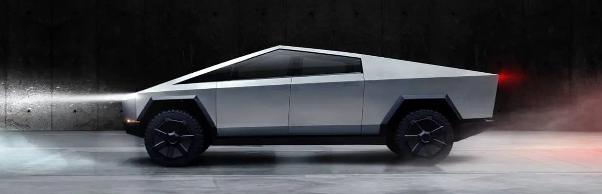
The Tesla Cybertruck, with its distinctive angular design, presents a unique case study in automotive aerodynamics. Despite its unconventional appearance, the Cybertruck achieves a commendable drag coefficient of approximately 0.34, enhancing its efficiency and range.
The Tesla Cybertruck, with its distinctive angular design, presents a unique case study in automotive aerodynamics. Despite its unconventional appearance, the Cybertruck achieves a commendable drag coefficient of approximately 0.34, enhancing its efficiency and range.
Wind - Tunnel
In CFD analysis, a "wind tunnel" refers to a simulated environment within the computational model that replicates the conditions of a physical wind tunnel, allowing engineers to study fluid flow dynamics around an object by virtually testing it in a controlled airflow, similar to how a physical wind tunnel would be used to analyze real-world designs; essentially, it's a digital representation of a wind tunnel used to test and analyze aerodynamic characteristics of objects without building a physical model in a real wind tunnel.
Applications of wind tunnel simulations in CFD:
- Aerospace design: Analyzing the aerodynamic performance of aircraft components like wings, fuselage, and control surfaces.
- Automotive design: Studying the aerodynamics of cars to optimize fuel efficiency and handling
- Building design: Assessing wind loads on buildings to ensure structural integrity
- Renewable energy: Evaluating the performance of wind turbine blades
STEPS / PROCEDURE :
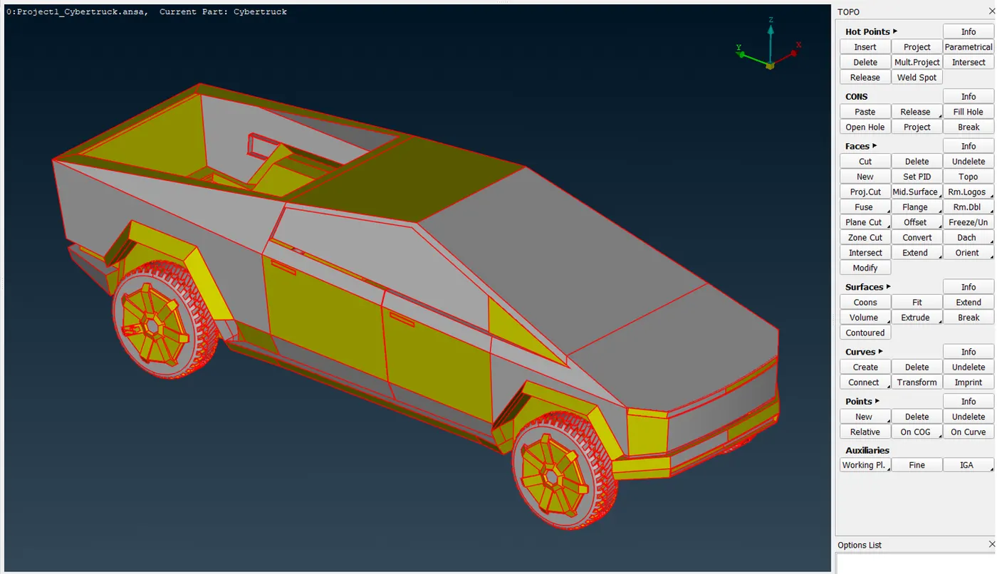
1) Loading Geometry
The Following is the geometry given -
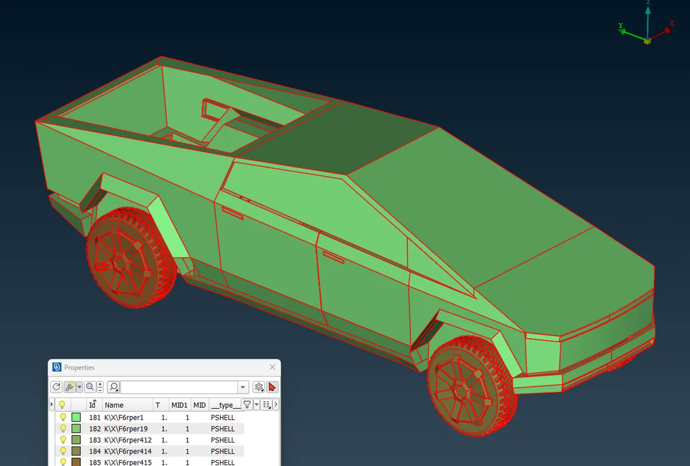
Selecting the PID view -
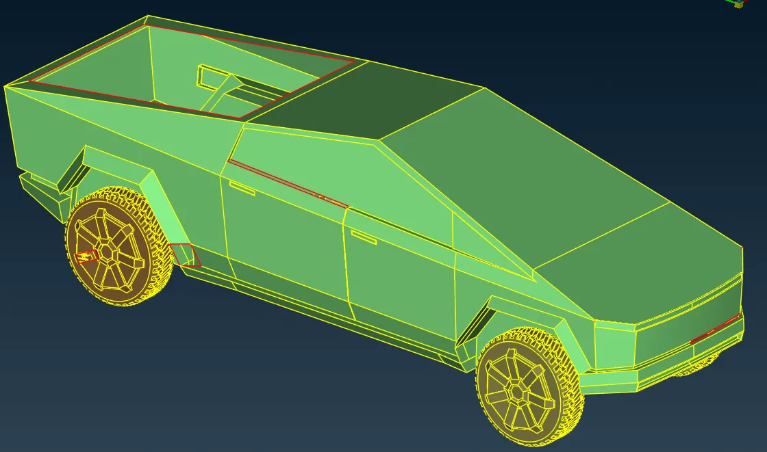
Doing Topo operation over the overall geometry in order to stitch up all the single cons
2) Geometry Cleanup
Before proceeding to meshing, we will improve the geometry using tools in TOPO deck.
The first thing to do is to check the remaining single cons and triple cons in the model. These are identified using geometric check tool.
As Shown below we got this much singles cons after performing the geometric check.
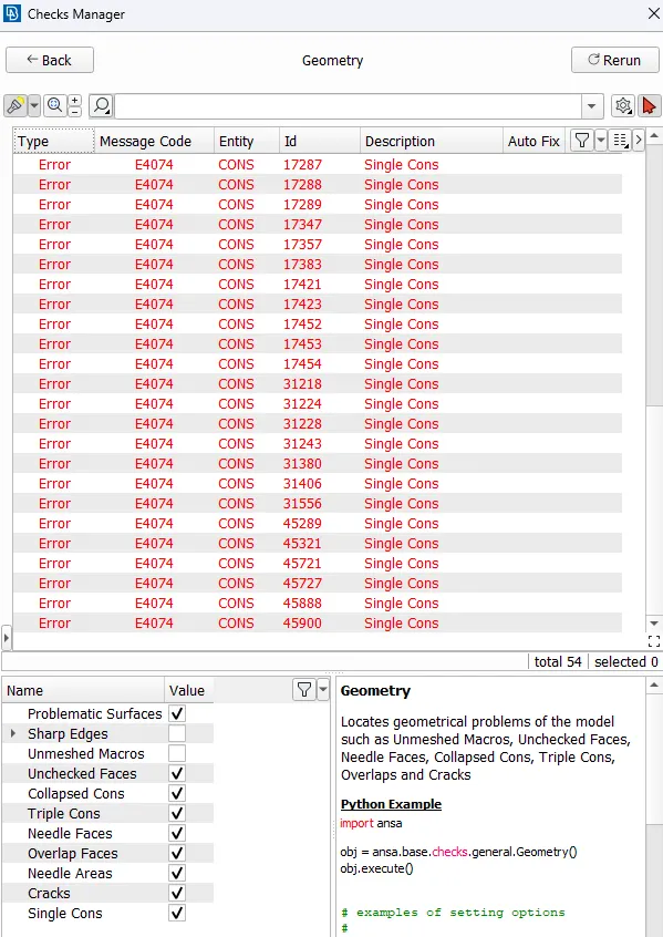
We can see from the Topo check and following image, there are many Single and triple cons.
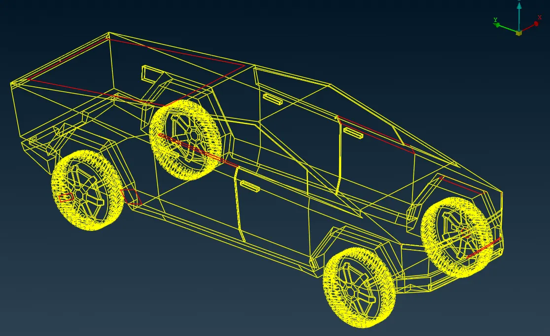
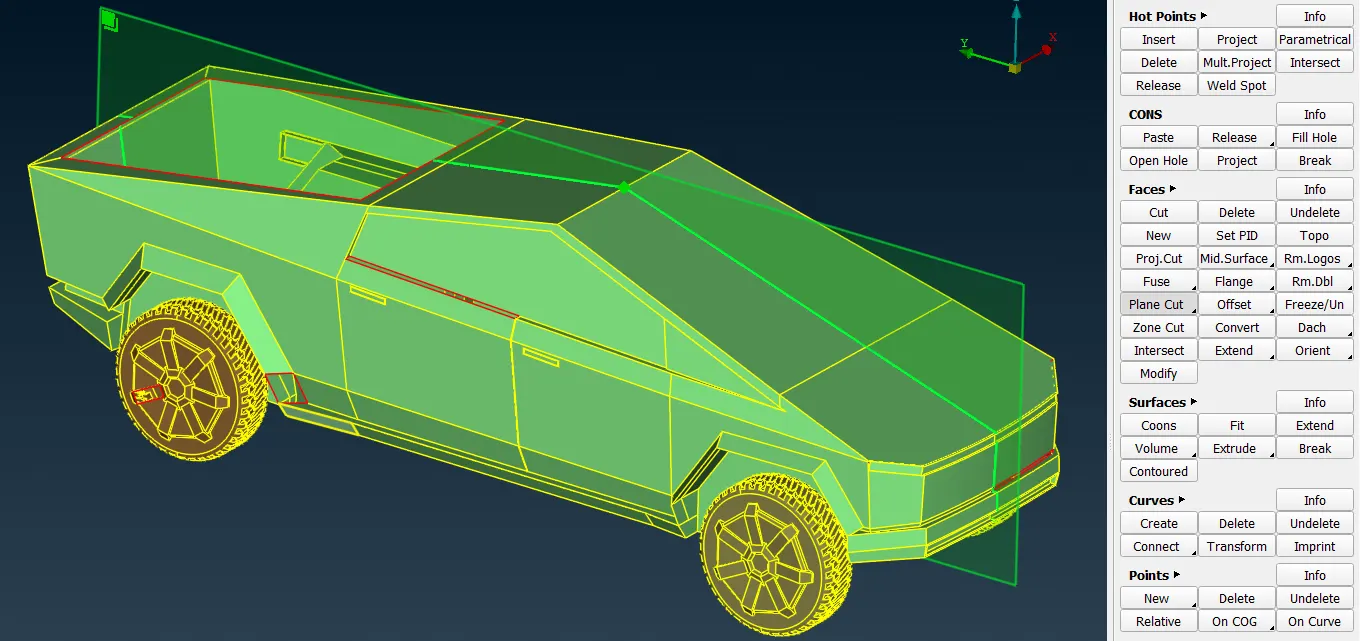
Now, in order to solve the geometry errors, before proceeding we have to cut the geometry in half since it is symmetric. But we can see that there is no center divide present. Therefore, cutting geometry in half using Plane Cut tool.
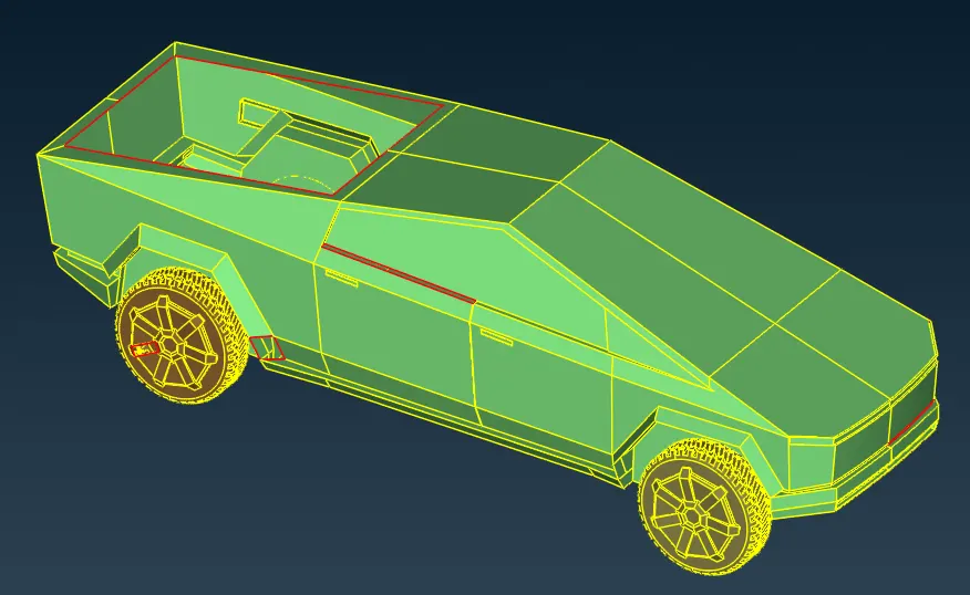
We the car is symmetric therefore we can delete one half of the car, which can be recreated later.
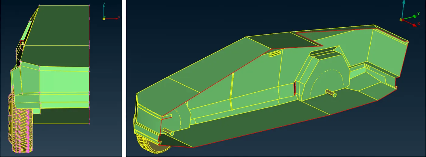
Deleting Overlapped unnecessary surfaces. Also, for the separated cons as shown below using Paste option.
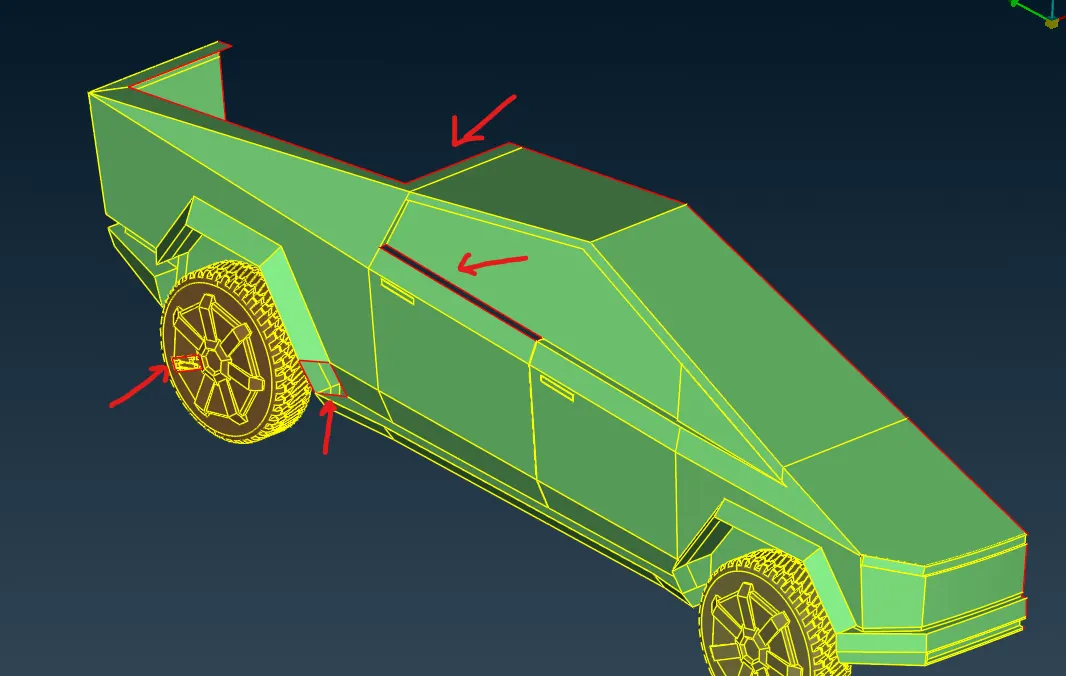
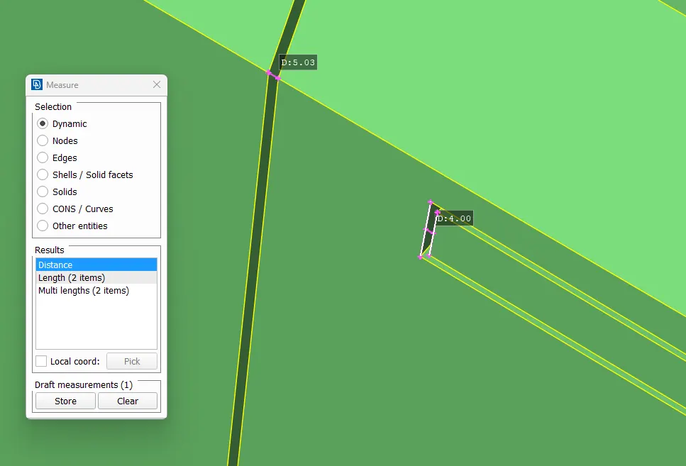
From measure tool we can see these minor gaps between the doors and handle notch. For the analysis of the car these geometries don't play a major role so we can make it simpler for the meshing.
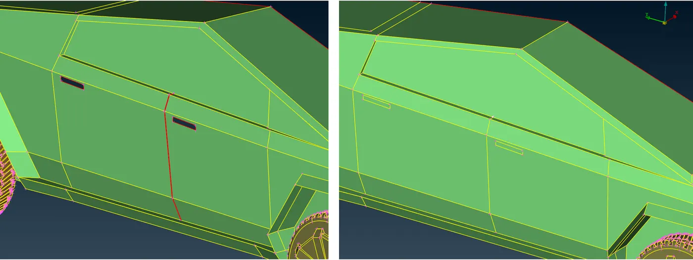
Following is the upgraded simplified geometry.
Deleting the overlap surfaces. and also deleting and recreate surfaces to avoid multiple volumes.
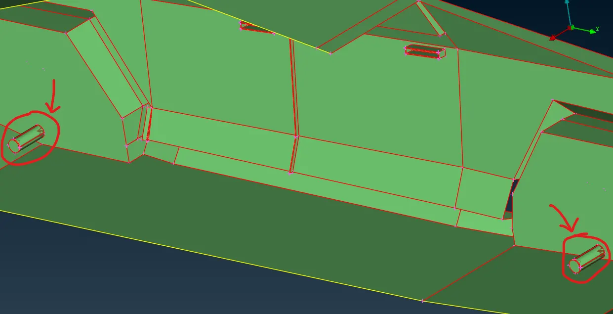
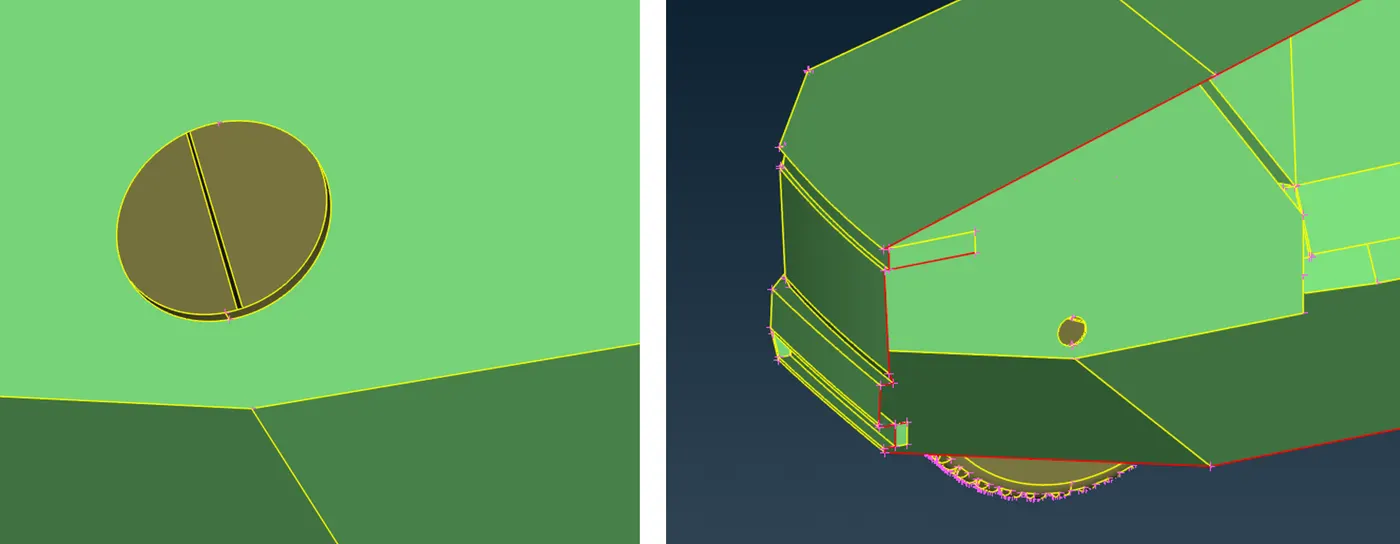
now we will have only one single volume to subtract from the wind tunnel for the analysis.
Following we can see the needle face errors. we can improve it with cut, new face creation tools.
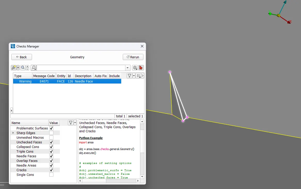
Also, we can use them to simplify the surfaces near it as shown below. removing intersecting and extremely narrow surfaces at their juncture.
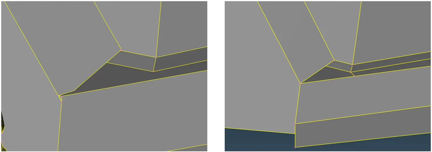
We can use intersect tool in order to solve overlapped and enlarged surfaces. Also, we will delete and create surfaces such that it will have one closed volume.
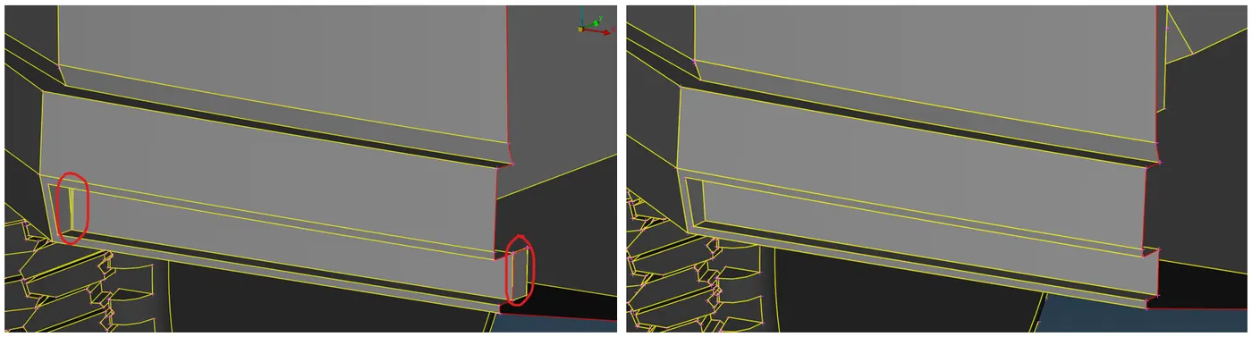
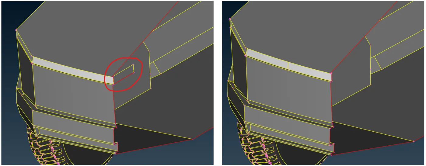
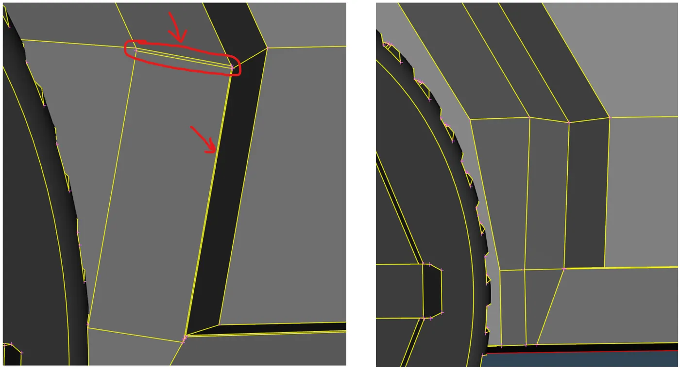
After doing that, we can proceed to other surfaces. The Following are the thin surfaces which can be simplified for reducing mesh complexity.
After doing the topo cleanup for all the PID surfaces, we will perform a geometry check. As you can see below the only single cons remaining are the ones, which will get attached to the other symmetrical half of the car body.
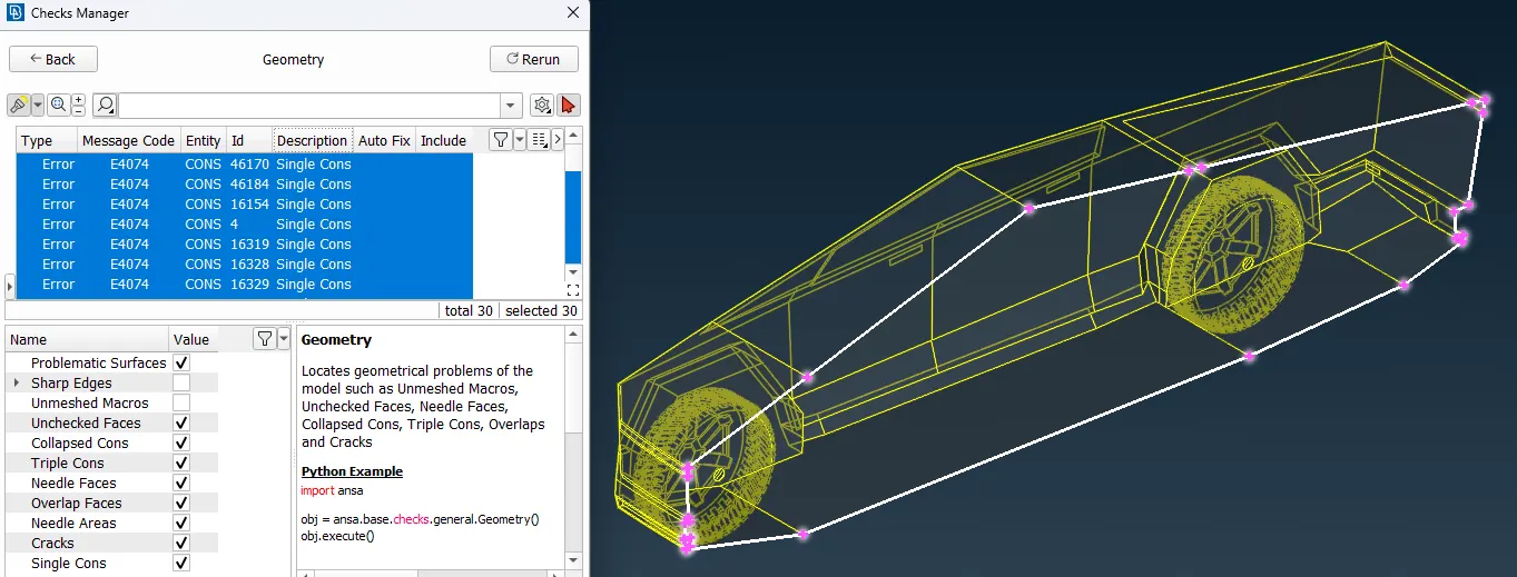
Hence all major geometry cleanup is done.
Following is the complete geometry looks like after geometry cleanup-
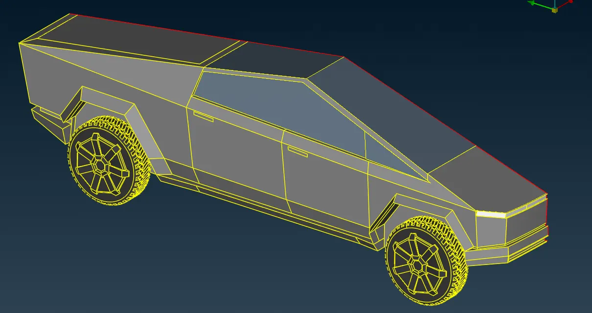
After completing with the topo cleanup, we can assign the PID to the set of surfaces which designated part of the components
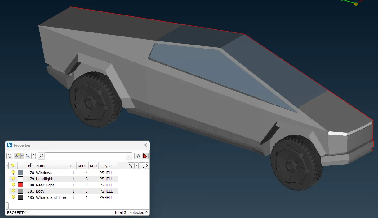
After Completing with the Topo cleanup and PID assignment we move towards the Meshing.
3) Meshing -
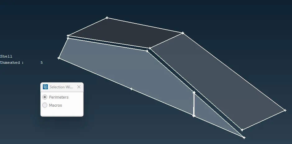
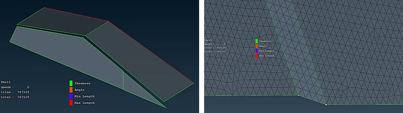
Before proceeding to meshing we can also improve the surface geometry for getting a good optimal mesh. We can see from the following images there are few areas where the cons/edges are too near and forming very narrow width surface, in the those areas we can remove cons by selecting cut tool from topo and right click on that edge. This way we can reduce the very small size mesh elements there and can have an uniform mesh over the surface as the target length.
From the Classic Mesh deck, we can use the length tool in order to assigning target mesh length size to the geometry.
Following are the mesh lengths given for the different parts of the TESLA Cybertruck -
- Body - 5 mm
- Head lights = 3 mm
- Tail lights = 3 mm
- Rims and tires = 2 mm
- window - 2 mm
Before proceeding to assigning length to cons and macros, we can manually measure the min. distance for each and every PID. Now from the measurement have got an idea a max. and min. range of mesh length for every PID, and Target length we already have. and it is the minimum gaps were above 0.5 mm.
(The target length will behave as the average length which will be between the min. and max. length)
For doing the meshing,
First, we assign the meshing criteria and then assign the mesh parameters.
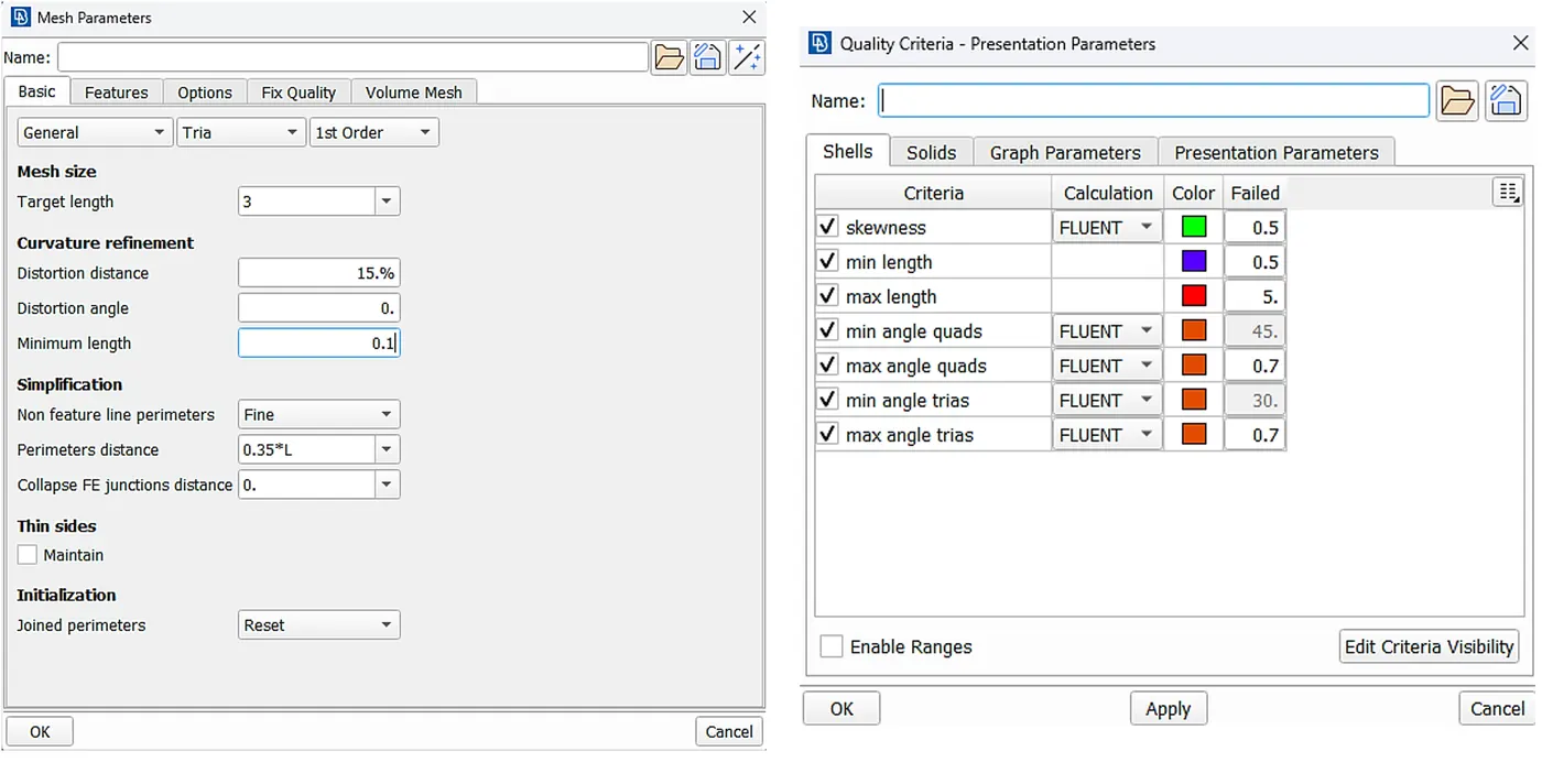
Starting with the PID - Head Lights and Tail lights
In Length tool, we assigned 3 mm size to all faces in both parameters and macros.
With min and max length criteria, be 0.5 and 5 units respectively.
In the Mesh Parameters Section, we will assign 1 mm to the target length.
And setting the Mesh element to Triangle elements.
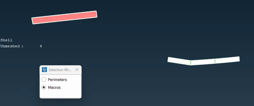
Then, we will proceed to generate mesh using Spot meshing tool.
After generating spot mesh we will click on the hidden option in toolbar below. we will be able to the see the mesh quality and no. of off elements.
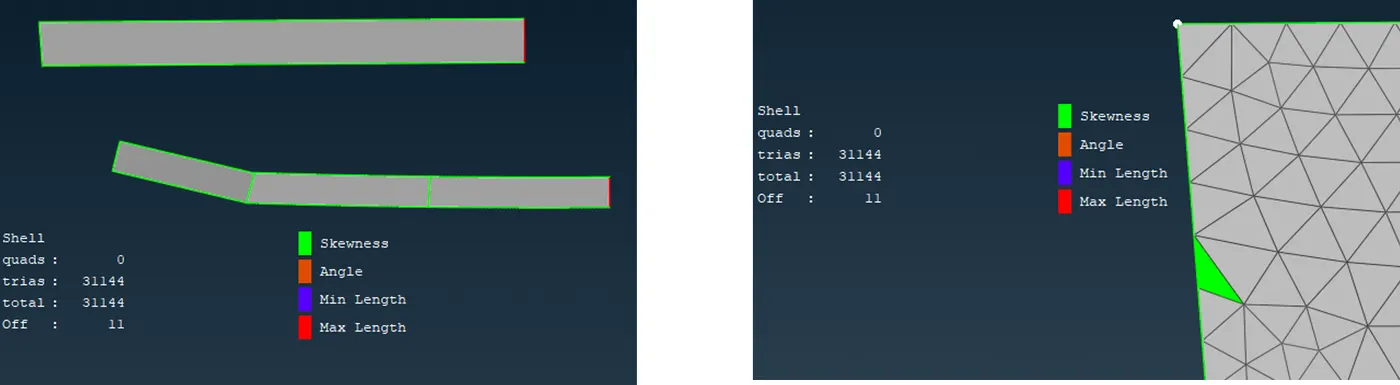
Now after doing spot mesh, we can now perform a Reconstructing tool on the surface from the classic mesh deck. After applying that you can see there are no off elements. Also, we can you move tool in the mesh deck in order to move nodes and improve the quality for the remaining mesh quality errors.
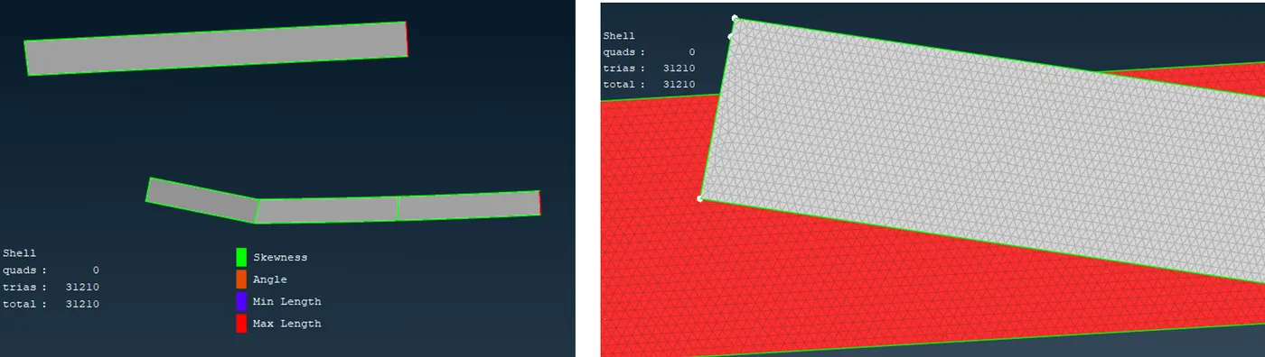
For PID - Windows
Target length = 3 mm
Min. size = 0.5 mm
Max. size = 5 mm
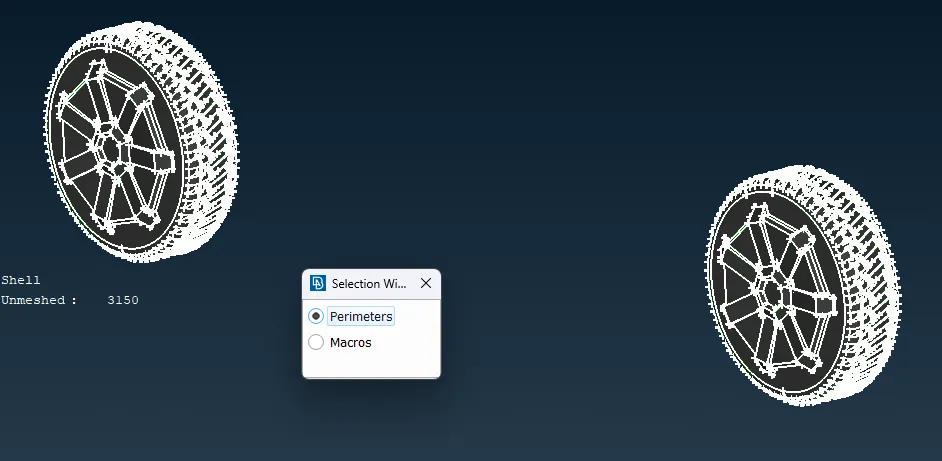
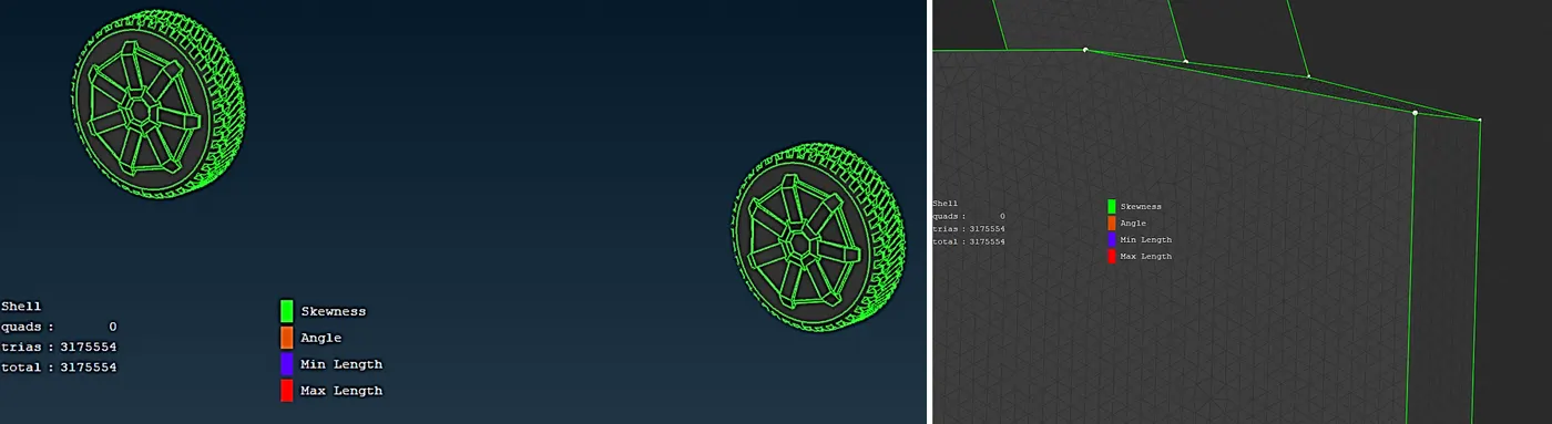
For PID - Rims and Tires
Target length = 2 mm
Min. size = 0.5 mm
Max. size = 3 mm
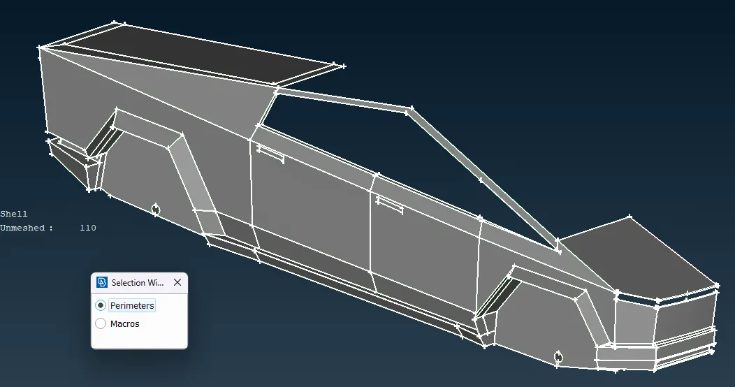
For PID - Body
Target length = 5 mm,
Min. size =0.5 mm,
Max. size = 6 mm
After, doing the Surface/shell meshing on all the PIDs and doing the resolving the off elements of the mesh. We can check the Mesh of all surfaces together and see the total mesh count.
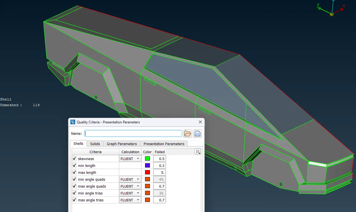
We can see that the mesh length of the element ranges from 0.3 mm to 5mm. And the total no. elements after surface meshing.
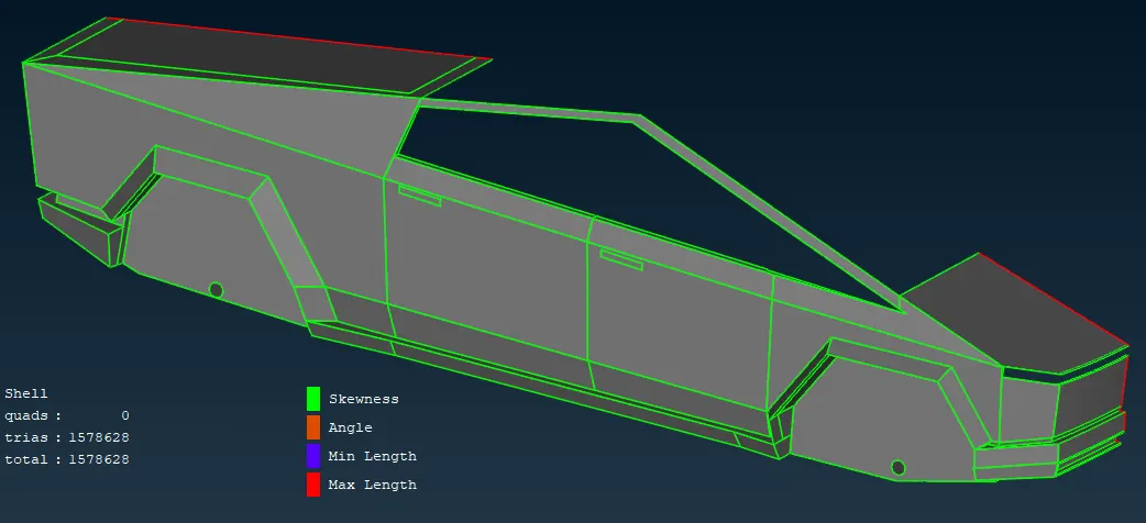
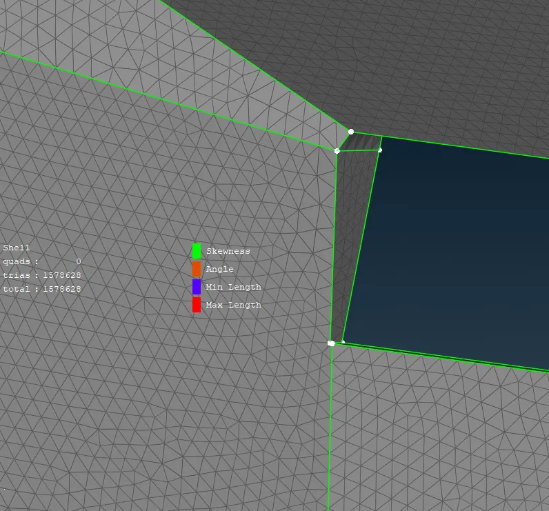
Now as we can see we have created the perfect shell mesh for the one symmetric half of the car.
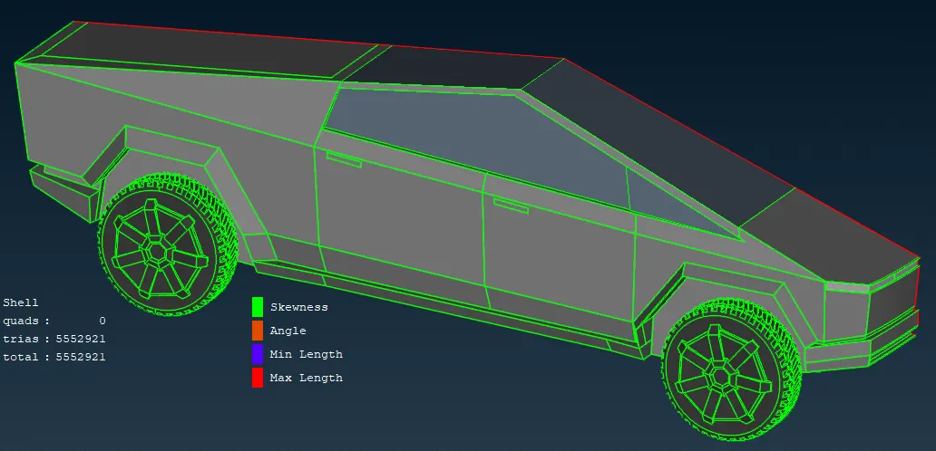
The Next part is to create other symmetric half of the car. We can do this by using Copy entities tool, in that there is Symmetry .
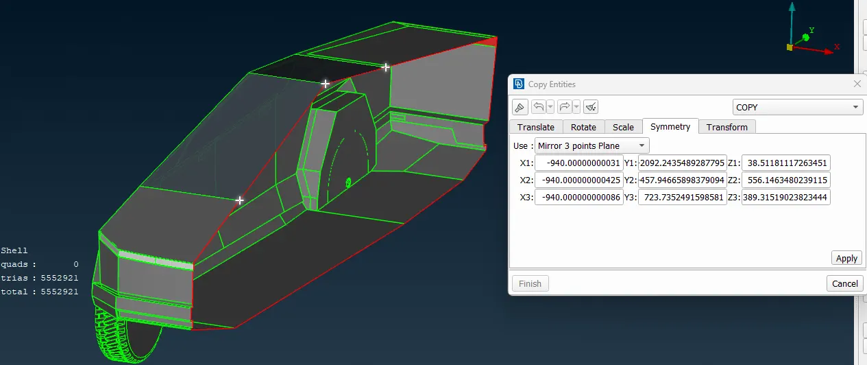
From the Single cons on the center of the car we can select 3 points and create symmetry by choosing the option of Mirror points plane. Which will create mirror copy of the selected surfaces, and select no-offset option to create surface just over the cons.
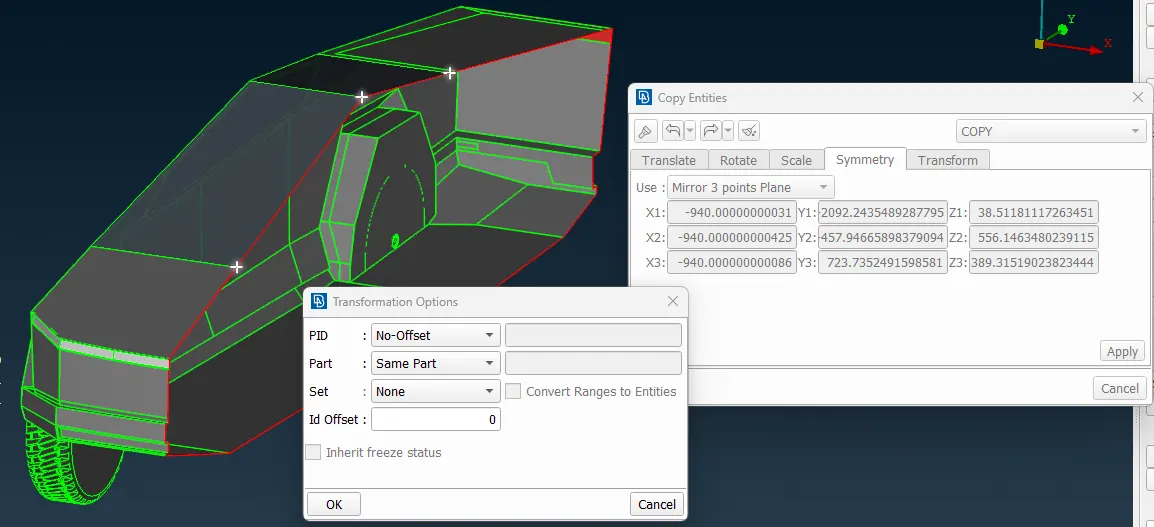
After Symmetric copy, following is the whole car surfaces & mesh
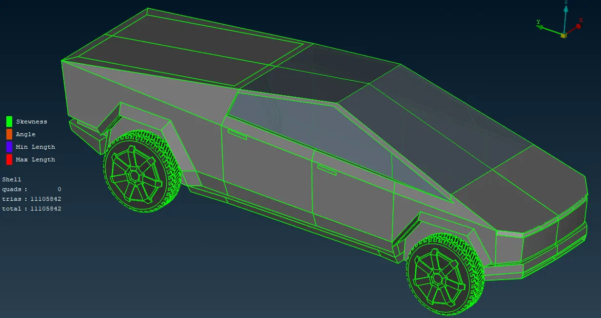
now we can use topo and paste tools in order to solve any mis-attachment. Also, we can perform a geometric check.
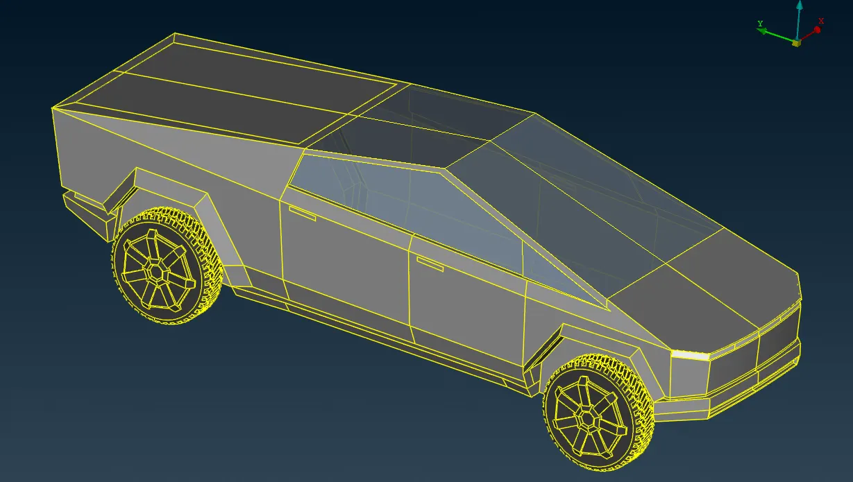
After completing the surface mesh, we can go to volume mesh deck for proceeding volume meshing.
Before creating the Domain and volume mesh, we will measure the length of the car from the front to the back.
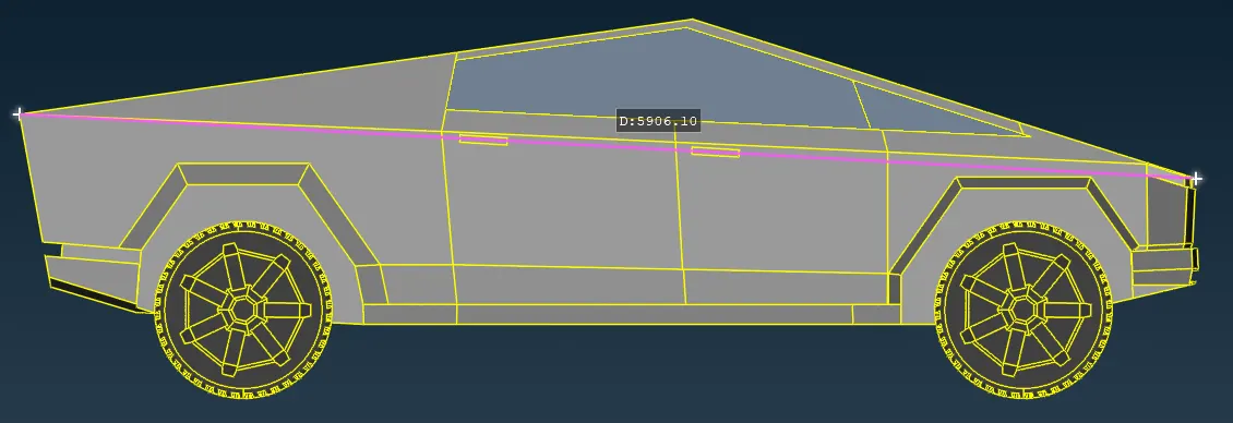
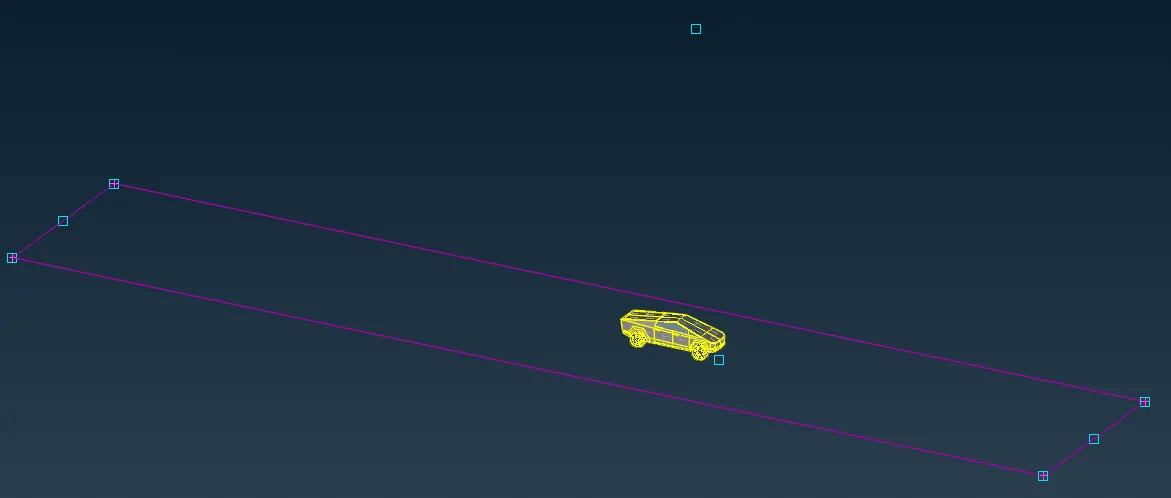
First, we will create respective reference points around the car and creating 8 corners of the Wind tunnel domain we need to create.
The wind tunnel is designed with respect to the dimensions of the model. If the model has ‘D’ mm length, then the front face of tunnel must be at ‘4D’ mm distance, the rear face must be at ‘6D’ mm distance and the top face must be at ‘3D’ mm distance from the top point, the bottom face must be below the model with a considerable gap and in the top view, the side faces of the tunnel must be ‘D’ mm on either side.
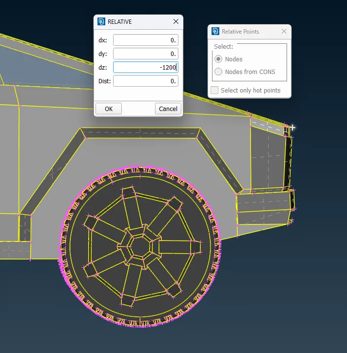
Select ‘relative’ option in ‘points’ menu and select a point at the base and in Y-axis set an arbitrary distance.
Following the point was taken from the hood the most extreme point of car to create the point below for the base.
Using these reference points we will create the Curves.
Now from these curves we will create surfaces of the wind tunnel domains, top, bottom, front, back and sides.
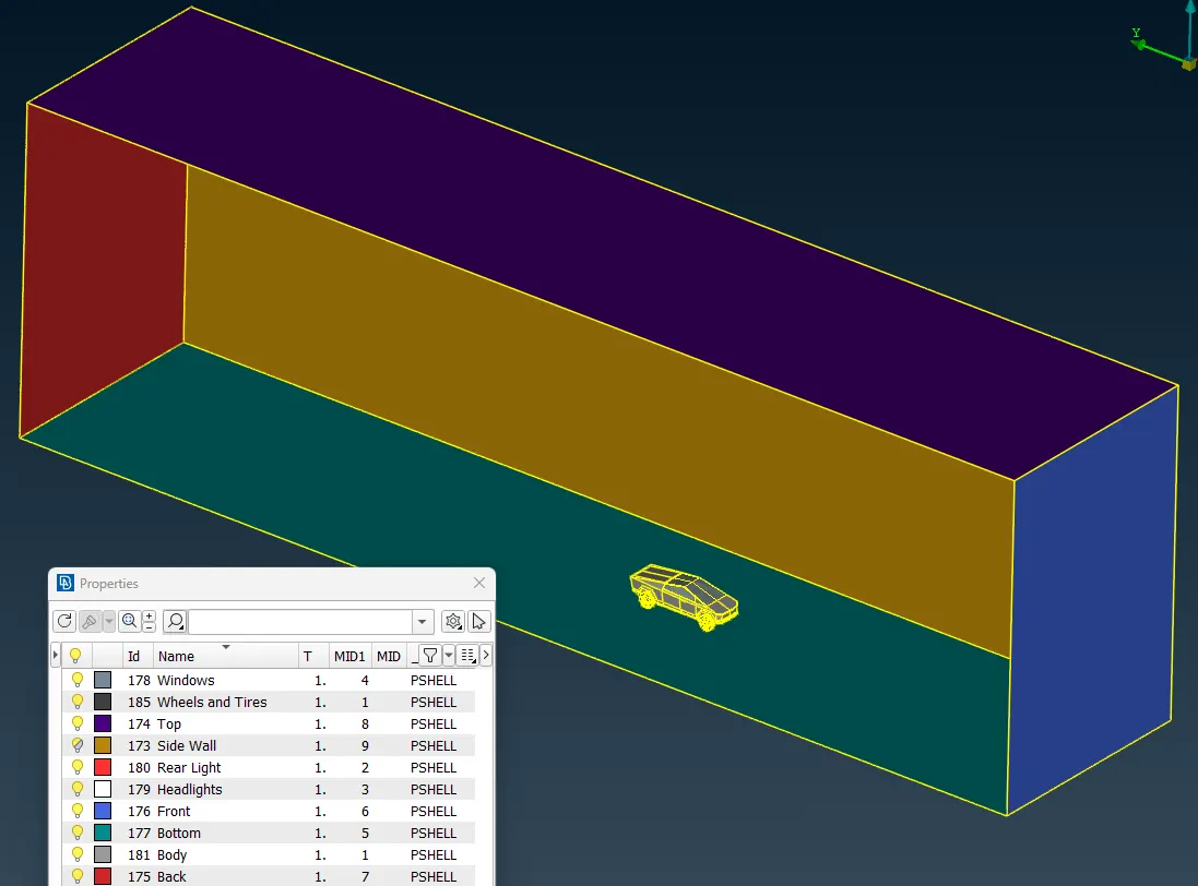
After creating the domain surfaces and assigning them PID, we will proceed to the shell/surface meshing of these domains.
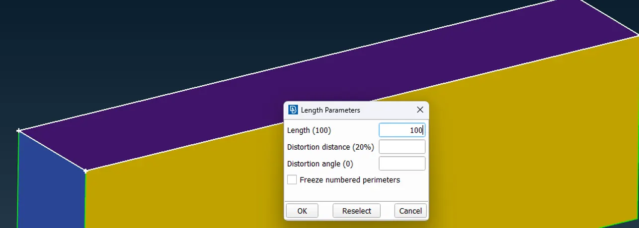
For surface meshing we will assign the lengths to the surfaces. The length will depend on how we want to generate volume mesh cells. For the Current case of Tesla cyber truck car simulation, the mesh cells near the track (Bottom surface) will be Finer than the mesh cells on the top face. Therefore, we will assign mesh lengths to be -
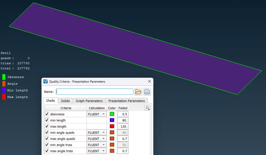
For Top face = 100 mm
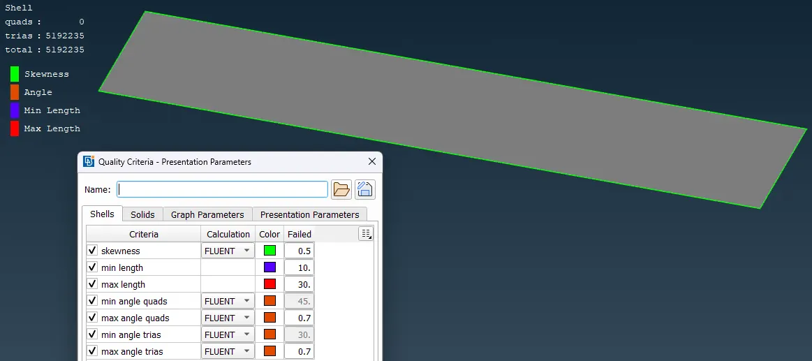
For Bottom Face = 20 mm
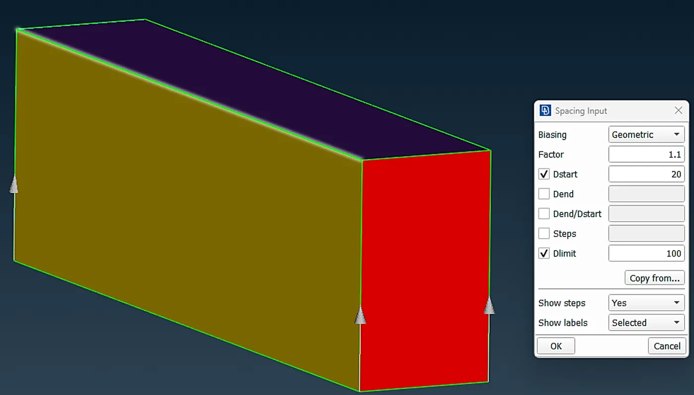
After Doing that we will create the gradient size of mesh lengths for the volume mesh, by creating and applying the gradient mesh length on the four edges between top and bottom face. So, the mesh length will be increased 20mm to 100mm with factor of 1.1 mm from bottom to Top face.
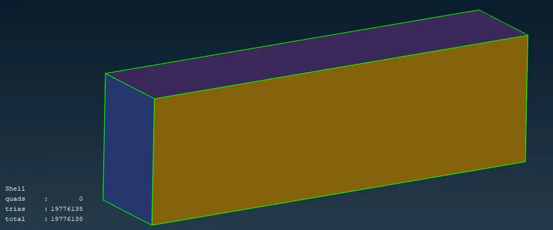
Following is the completed all surface meshing with Car + Wind tunnel , with mesh length quality criteria for all surfaces ranges from
Min. 0.5 mm to Max. 120 mm
Now Moving to the Volume Meshing
By define option we can check/scan for the volumes from the surfaced mesh geometry.
Following are the detected volumes
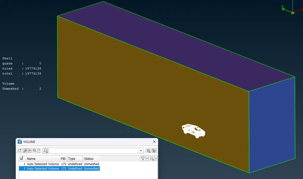
Now We will delete the Solid volumes which are the body of the Car and just keep the fluid volumes.
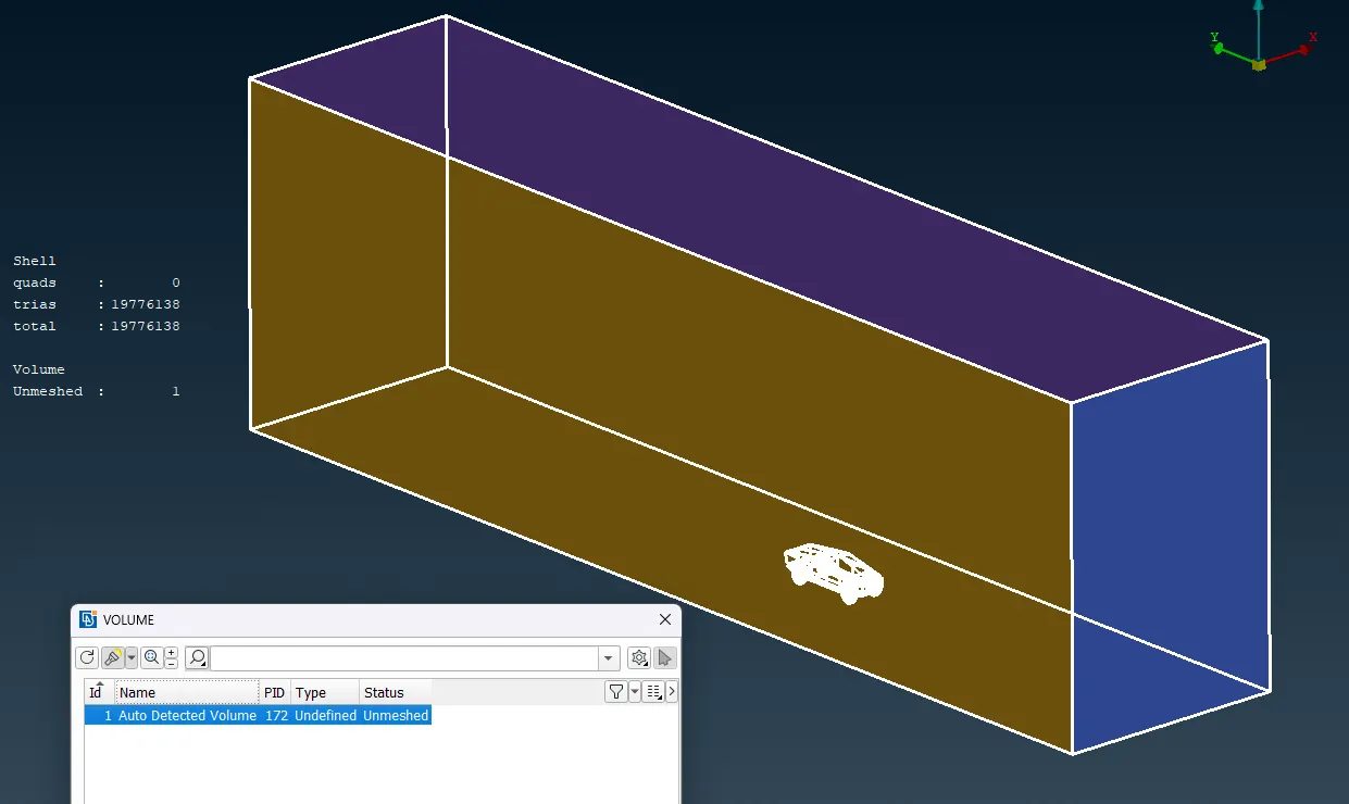
After deleting solid volumes. From the properties tab we can see the mesh status.
By clicking over the unmeshed tab, we can see different meshing option and we gonna use Tetra rapid option for optimal meshing.
After that we have to just click and generate the volume mesh.
Note: The volume mesh was not generated because of the high computational requirement and log computation time.
After generating Volume Mesh, the process is the same we need to check the mesh element quality of the Volume mesh.
CONCLUSION :
We have successfully created the mesh for the CFD of the TESLA Cybertruck .
In this project we have used different new tools in the ANSA in order to generate the volume mesh.
We have seen different tactics and ways for the surface correction and geometry optimizations in order for the optimum meshing.
Used tools like symmetry copy, points, curves etc. for creation of the surfaces.
We have seen reconstruct, grid move, etc. tools in order to improve the off-quality elements.