Project 1 : CFD Meshing for Tesla Cyber Truck
Aim:
(i)To perform the Geometry cleanup of the Tesla Cyber Truck CAD Model.
(ii)To convert the multiple volumes inside the truck CAD model into single volume.
(iii)To Perform surface meshing with different target lengths for the truck model.
(iv)To create the windtunnel over the CAD model.
(v)To Perform volumetric mesh between the Truck CAD model and Wind tunnel.
Introduction:
CFD analysis consists most commonly three stages (i)Pre-Processing (ii)Solving and (iii)Post-Processing.Pre-Processing stage includes creating geometry,Mesh,specifying the boundary and equations.Solving stage made up of algorithms implemented on the governing equations.Post-Processing will output the results by using the visualisation tools.First step of Pre-processing is Product modelling such as complex geometries are created using a specialised CAD software,Creating a complex geometries may gives raise to unwanted surfaces.Geometry cleanup is preparing the surface geometry for the Meshing by removing the topological issues (needle faces,unwanted surfaces,overlapped surfaces and recreating the missing surfaces) and for external (or) internal flows,creating the faces to separate the inner volumes from outer volume etc..,.To do the geometry clean up ANSA software is used.ANSA provides functionality from CAD import to ready to run by solver and its GUI is customisable and it can handle large model sizes.It has a feature identification tools to identify the topological issues. Meshing is a process of splitting the volume (or) surfaces into multiple elements.Collection of all these elements are grid (or)mesh.The process of obtaining the appropriate mesh is termed as mesh (or) grid generation.Meshes are created by computer algorithms,often with human guidance through a GUI,depending on the complexity of the domain and type of the mesh. ANSA provides a variety of Algorithms for the surface meshing i.e.., Advancing Front,Free,STL,CFD,4 sided,Circular,Batch,map,Spotmesh,gradual,best and for Volume meshing i.e.., unstructured meshes-Tetrarapid,TetraCFD,TetraFEM,HexaPOLY,Hexa Interior and structured meshes-Map,Layers,Extrude,glide,sweep,Dual sweep,Hexa block.Each Algorithm has a different applications.Moreover surface meshing creates 2D elements in the shape of triangular/ Quadrilateral by relavent algorithms and volumetric meshing creates 3D elements in the shape of Tetra/Penta/hexa not by all algorithms,All volumetric algorithms can create the mesh particulary one (or) one among the two shapes.Discretization schemes convert the Flow governing equations into the set of alegrabic equations based upon nodes (or)volumes.ANSA provides a lot of tools to give a better quality mesh.Mesh Quality depends on several factors such as shape,size,aspect ratio,skewness,smoothness and alignment of the grid cells.Briefly,the aspect ratio is the ratio of a cell's longest length to the shortest length.the ideal aspect ratio is 1.Calculation method varies based on the cell type.Hexahedral cell aspect ratio is the ratio of maximum edge length to the minimum edge length.Tetrahedral cell aspect ratio is ratio of maximum edge length to the product of 4.9 and radius of cell's internal sphere.Skewness is the deviation between the optimal cell size to the existing cell size.The ideal skewness is 0.Calculation method varies based upon the cell type.
Wind Tunnels are the machines where an object is held stationary inside the tube and air is blown around it to study the interaction between the object and the moving air.They are used to test the aerodynamic effects of aircraft,rockets,cars and buildings.Air is blown or sucked through a duct eqiupped wih a viewing port and instrumentation where models or geometrical shapes are mounted for study.Typically the air is moved through the tunnel using a series of fans.Instead of single fans ,an array of multiple fans is used ,it is powered by stationary turbofan engines.airflow created by fans entering the tunnel with turbulence.Mostly tunnel in the shape of circular because sharp corners will have a greater flow constriction.To view the flow behaviour through transparent portholes of the tunnel,Methods are developed,those are smoke,carbon dioxide,tufts,Evaporating suspensions,oil,tempera paint,Fog,sublimation etc..,some methods to measure they are pressure sensitive paint,PIV,MDM.There are different kinds of the wind tunnels classified based on velocity 1.Low-speed wind tunnel 2.High speed wind tunnel 3.subsonic and transonic wind tunnel 4.supersonic wind tunnel 5.Hypersupersonic wind tunel 6.high enthalpy wind tunnel
some tunnels are classified based on the aeronautical wind tunnels 1.high reynolds number tunnels 2.V/S TOL tunnels 3.Spin tunnels 4.Automotive tunnels 5.Aeroacoustic tunnels
Some tunnels are classified based in construction 1.open return wind tunnel 2.closed return wind tunnel.
Procedure:
1.Start->ANSA is selected then ANSA launcher window will appear then CFD layout is selected then changed the Additional ANSA Command arguments other from -changedir to the -performance_mode 3
Reason for changing the additional ANSA Command arguments is need to have a clear drawings
Importing the CAD geometry
2.File->open is selected then open window appears then locate the file then select the file by clicking left mouse button then select open by placing the mouse over the button and click left mouse button.
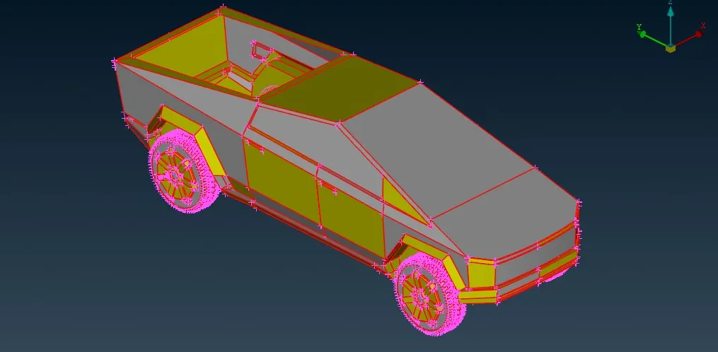
Geometry Cleanup
3.Model is displayed in the form of single CONS.To display as solid model click Drawing styles->shadow.To update (or) converting the multiple single CONS into double (or) Triple CONS of the model by selecting the Topo->faces->topo then select the whole model by using the box select then scroll mouse button is clicked to end the selection of the CONS.
4.observed the model,there is a presence of single and triple CONS.Model is splitted by creating the curves at the middle.Topo->curves->middle option is selected then selected the CONS then scroll mouse button is clicked then selecting the 2nd group of CONS then mouse scroll button is pressed.curves created at center then topo->faces->Plane cut is selected then Nodes is selected then scroll button is clicked then splitting faces is selected then scroll button is clicked.
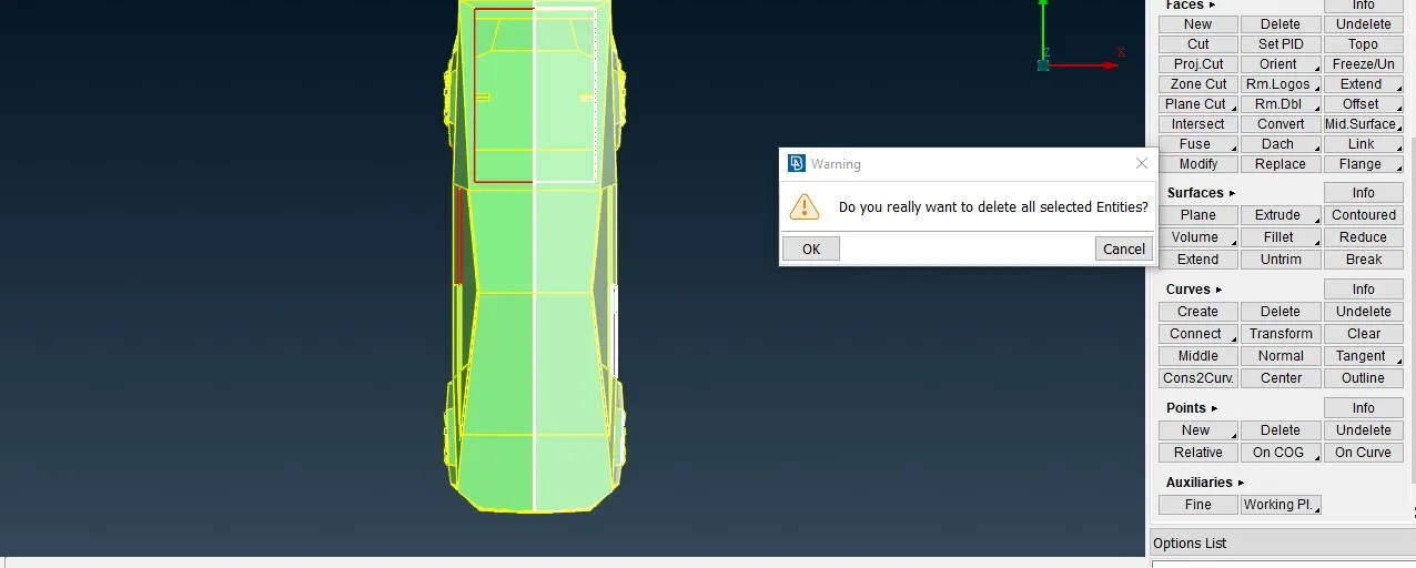
5.Now,geometry is splitted into two halves,Among that one half is deleted by selecting utilities->delete option then one half is selected using box select then scroll button is clicked then warning window appears then click ok button.
6.Presence of single CONS on this model is mostly due to the missing surfaces,so creating the new surfaces by selecting the topo->faces->new then new face options window appears then COONS algorithm is selected then CONS is selected then scroll button is clicked then COONS window appears then ok is clicked.
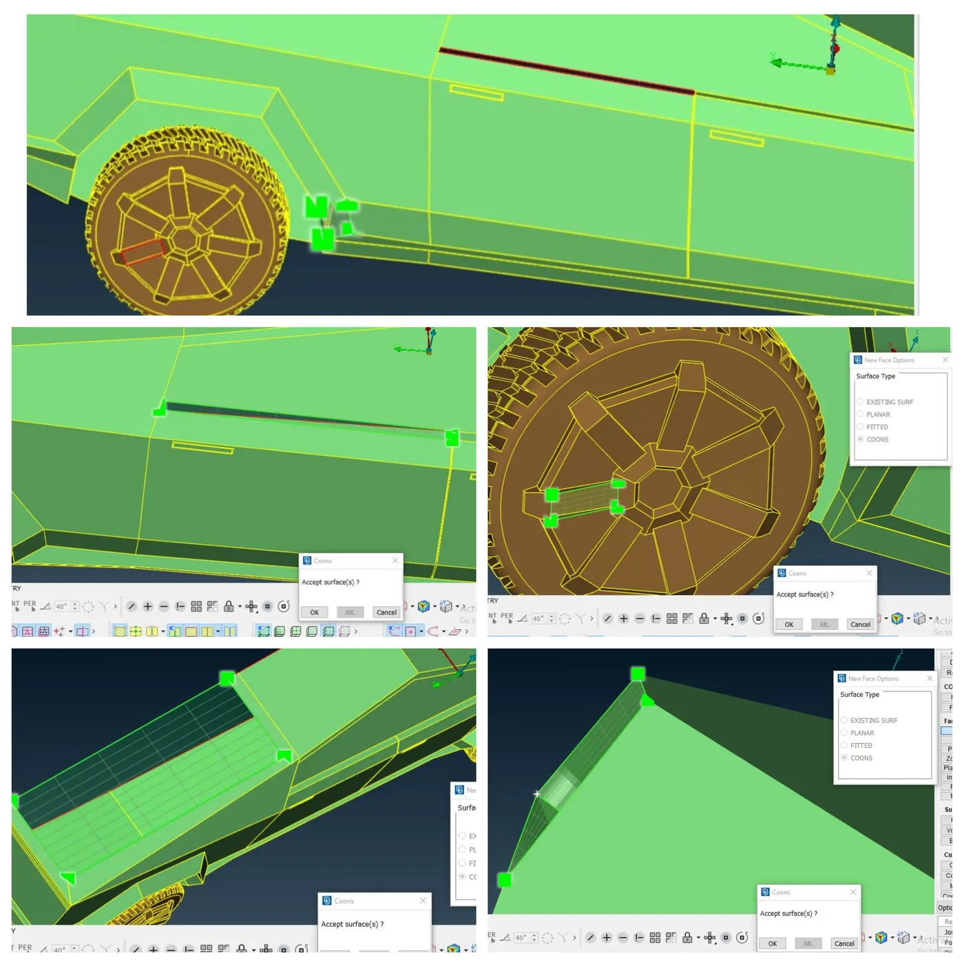
7.Presence of triple CONS on the model due to unwanted surfaces.Removed those surfaces by selecting utilities->delete option then select the surfaces then scroll button is clicked then warning window appears click ok button.
After that topo->faces->cut is selected then right-clicked to remove the Cut.
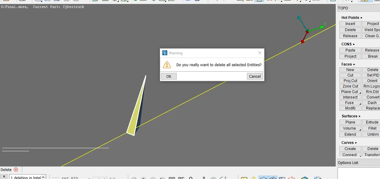
8.Deleting surfaces by selecting utilities->delete option .then surfaces is selected then scroll mouse button is clicked then warning window appears and then click ok button.
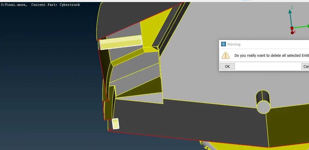
9.deleting the protuded surface by selecting topo->faces->cut option then select the points on the CONS then the splitted surface is deleted by utilities->delete option then select the face then scroll button is clicked warning window appears then click ok button.This would be repeated to delete the protude surfaces.
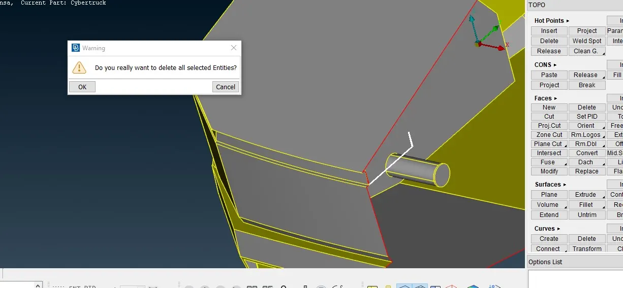
10.To make into one volume ,Deleting some of the surfaces by selecting utilities->delete option then surfaces are selected then scroll button is clicked then warning window appears then click ok button.then create the new surface by selecing topo->faces->new option then Fitted algorithm is selected then CONS is selected then scroll button is clicked then surface fit window appears then click ok button.
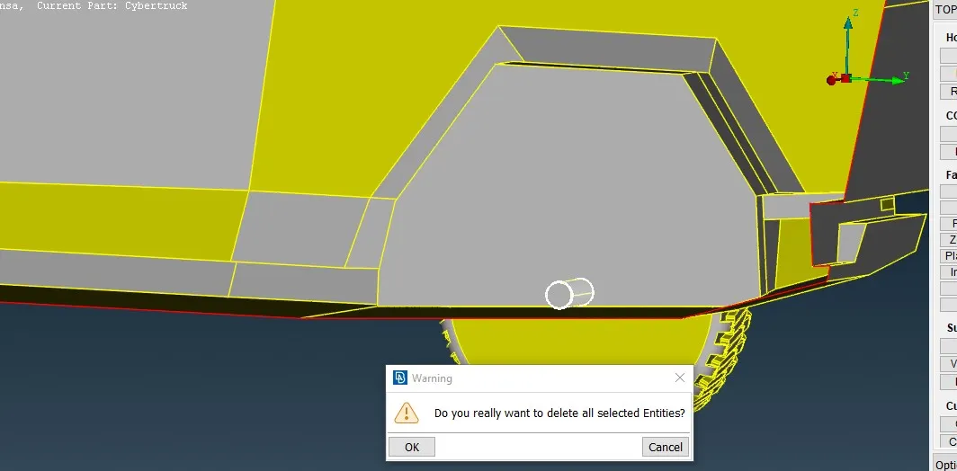
11.Tools->checks->geometry is selected then checks manager window appears then click execute.to know the presence of errors.After checking this,there is a lot of warnings present in the window then selected all those warnings to see those on the graphics window.
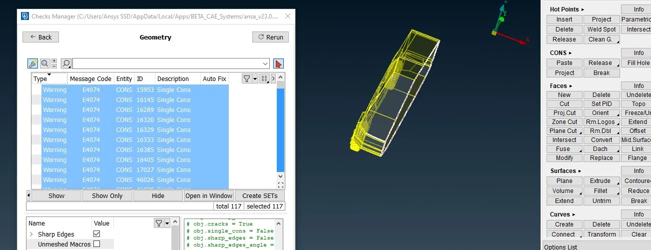
warnings are mostly due to single CONS.This will recitify once by forming full body using symmetry option.
12.Utilities->transform->copy option is selected then selection window appears entities is selected then selected the entire model using box select then scroll button is clicked then copy entities window opens then select symmetry tab on the use mirror 3 points plane is selected then manually points are selected then scroll button is clicked then on the appearing window click ok button and then finish is clicked on the copy entities window.
Assigning the PIDS:
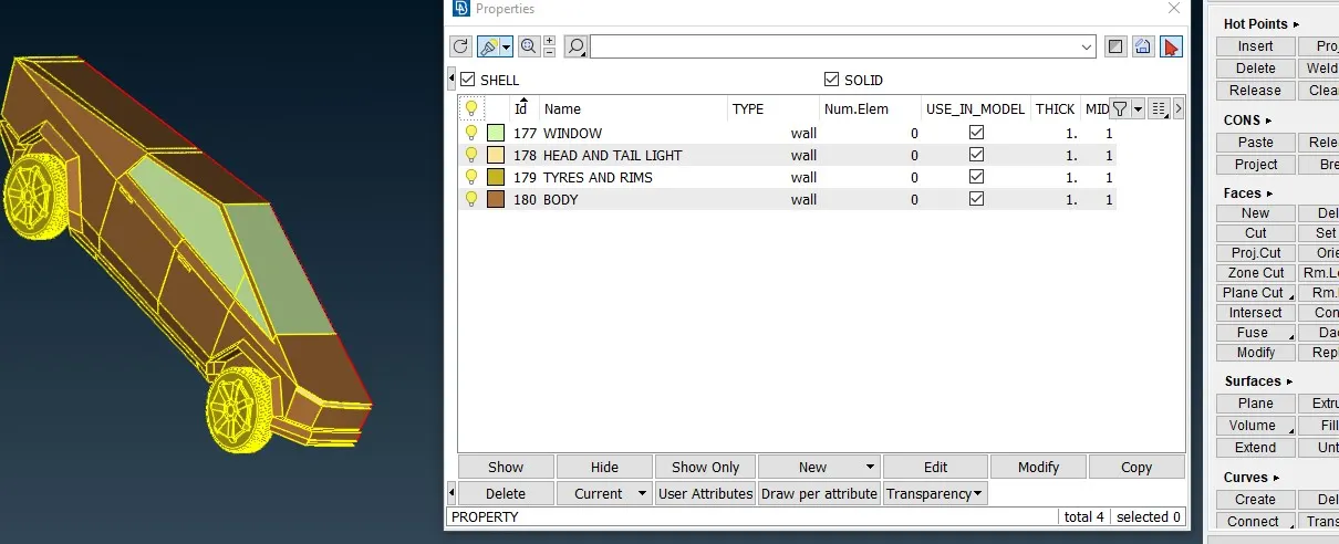
13.Property IDs are really significant for creating meshes.Initially created a four different PIDs by repeating the procedure as described below ,selecting lists->properties then properties window appears then new->shell property is selected then property window opens then enter the name and then click ok.
Each and every created PIDs is displayed on the list.selecting one particular PID then right-click using mouse then pop-up menu appears then select apply then select surfaces then scroll button is clicked.in the same way faces assigned to the PIDs
14.Utilities->compress option is selected to remove the empty PIDs present in the properties window then compress window appears then click ok.
Surface meshing
15.Before doing the surface meshing,checking the small surface measurements are necessary by using utilities->measure option is selected then selecting the nodes or CONS will displays a distance.
Based upon the distances at small area the target length for the mesh is fixed.
16.Meshing starts with small components.Module changed from topo to mesh by selecting Module->mesh then tools->properties is selected then select the PIDs then right-click on the mouse by placing the pointer then pop-up menu appears then select show only.
17.Then utilities->Quality criteria is selected.Parameters such as skewness,min length,max length,etc are selected by clicking the the left mouse button over the check box and entered the values and click ok.
values assigned for parameters are (i)skewness-0.5 (ii)Min length-0.1 (iii)Max length-6
then utilities->mesh parameters is selected then mesh parameters widow appears ,by default basic tab is selected then selecting a general (or) CFD mesh from drop-down menu (selection on the drop-down menu is depend on the algorithm of the mesh) appears .if the general is selected,for the target length drop down box appears then select empty one option then enter the value of length in it.on the curvature refinement section the minimum length value is entered then click ok.minimum length in the curvature section represents the minimum of target length.if CFD mesh is selected then values provide at minimum and maximum lengh then click ok.then mesh->perimeters->length or spacing -> auto CFDis selected then selection window appears then select perimeters then select the geometry end the selection by pressing scroll button then length parameter window appears then enter the target length in length then click ok.this is also followed for macros.
| S.No | PIDs | Target length | minimum length | maximum length |
| 1 | Windows | 1 | 0.1 | 2 |
| 2 | Lights | 3 | 2 | 4 |
| 3 | Rims and Tyres | 0.75 | 2.75 | |
| 4 | Body | 0.1 | 6 |
Select Mesh->mesh generation->spotmesh or cfd->visible.This meshes the displayed components.on the faces draw deselect the shadow and selecting the hidden will show the mesh statistics.
Meshing algorithm is choosen based on geometry complexity.meshing algorithm always choosen the spot mesh if it gives much off elements or unmeshed surface due to geometry complex shape then choosen variable elemental length meshing algorithm that is CFD to reduce the issues.
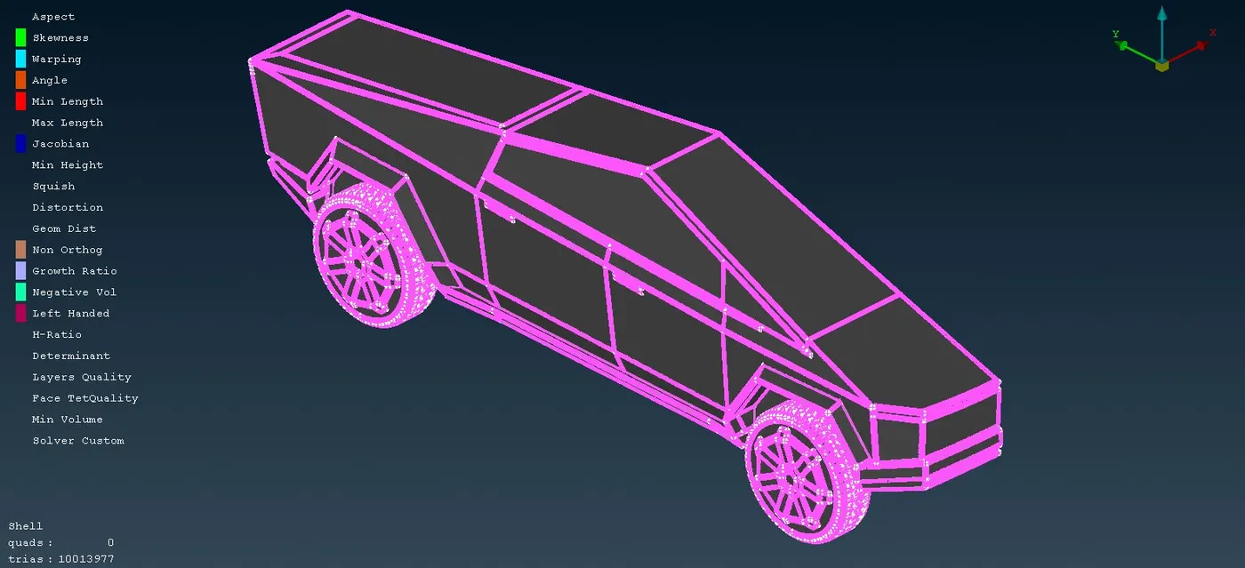
Then Mesh->shell mesh->Reconstruct->visible option is selected then reconstruct edit parameters window appears then click on the next then reconstruct preview window appears then click on the finish.(Reconstruct will be used multiple times until the off elements starts to increasing)
Then right click over the off elements wordings present on the left side of the graphics window then popup menu will appears then click improve then improve select window appears then click next then improve preview window appears then click finish.on the improve select window drop down box appears this will allow to select one among the four options i.e..,reconstruct,reshape,fix quality,smooth.(improve will be used multiple times until the off elements starts to increasing)
if still off elements are left then mesh->grids>move (or) mesh->elements->split (or)mesh->elements->delete and mesh->elements->new is used as needed single (or) multiple times.
From mesh parameters option to offelements solving will be repeated for every PIDs.
Symmetry
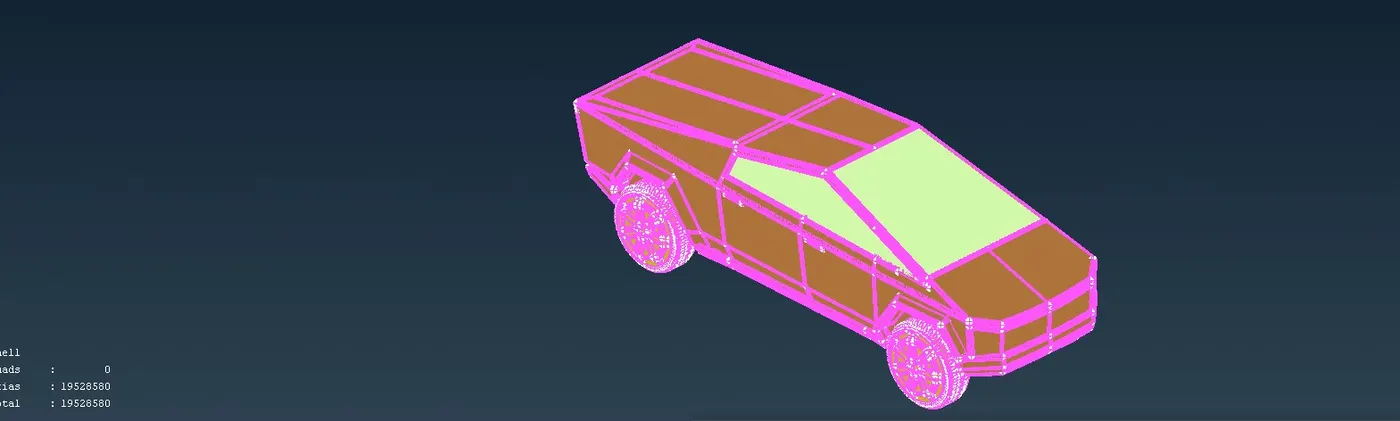
18.Utilities->transform->copy is selected then selection window appears then selecting entities then model is selected by using box select then scroll mouse button is clicked then copy entities window appears then select symmetry tab then drop dow menu appears from that selecting the mirror 3points plane then 3 points on the model is selected then mouse scroll button is clicked then transformation options window appears then click ok then click finish on the copy entities window.
19.There is some little gaps found with the presence of single CONS.those are solved by selecting topo->CONS->paste then selecting two single CONS then scroll button is clicked then paste CONS confirmation window appears then click ok.
20.After this,find some unmeshing surfaces.the faces are meshed based on PIDs parameter values.
Wind Tunnel
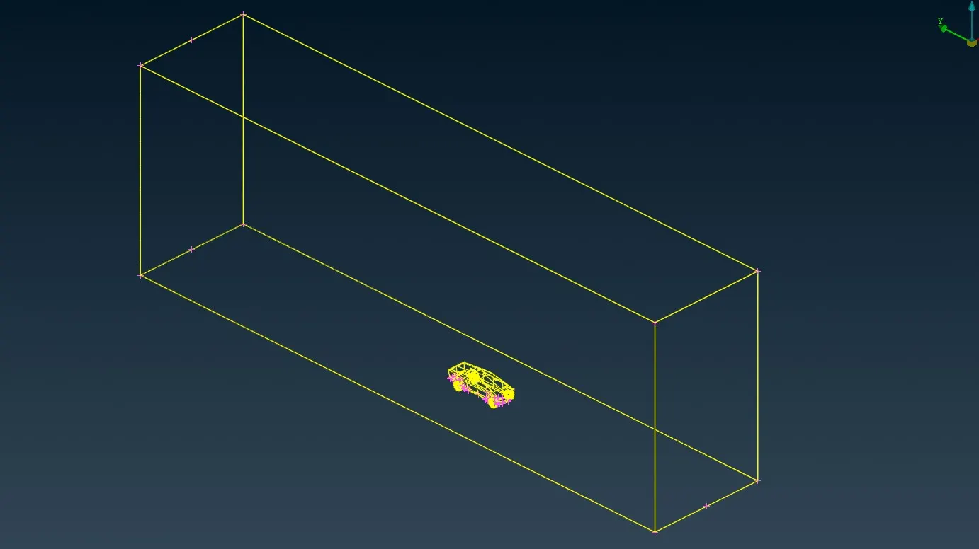
21.Creation of points by selecting topo->points->relative option then the relative points window appears then selecting the Nodes then node is selected then scroll button is clicked then relative window appears then enter the values then click ok.This procedure has be used multiple times to create the points.Below table gives the each point is created based on the reference and distance from reference point.
| s.no | Created point | Reference point | Distance from the reference point. |
| 1. | 1st point (bottom base point) | Node on the bottom side of the truck | dz--385 |
| 2. | 2nd point (Front side of the truck) | 1st point | dy=-23260 |
| 3. | 3rd point (back side of the truck) | 1st point | dy=34890 |
| 4. | 4th and 5 th point (sides of front and back point) | 2nd and 3rd | dx=5815 |
| 5 | 6th and 7 th point (sides of front and back point) | 2nd and 3rd | dx=-5815 |
22.Topo->curves->create is selected then curve create window appears then selected line and then selected each and every point to form a closed rectangular shape then scroll mouse button is clicked then topo->faces->new option is selected to create the base faces then new face options window appears selecting an algorithm then curves is selected then selection is ended by pressing the scroll button the mouse then properties window appears then right-click on the window select new->shell property then property window appears enter the name and then click ok then click ok button on the properties window then COONS window appears then click ok.
23.Topo->faces->offset option is selected then offset window appears ,select the face the direction will be generated based upon that value [19365] entered on the offset window then click ok.
24.Then creation of faces by selecting topo->faces->new then new face options window appears then CONS are selected then scroll button is clicked then properties window appears then right-click then popup menu appears then select new -> shell property then property window appears then enter the name click ok button then scroll button is pressed then COONS window appears then click ok button.
25.Creating the faces by selecting topo->faces->new then new face options window appear then select the COONS algorithm then CONS is selected then scroll button is pressed then COONS window appears then click ok.This will be used multiple times for the creating the wind tunnel surfaces.
26.Creating the PIDs by selecting the lists->properties then click new->shell property then property window appears then enter the name then click ok.This will also done multiple times for creating the required PIDS for the wind tunnel.
27.Then assigning the surfaces for the PIDs by right-clicking on the properties window then pop-up menu appears then select apply then select the faces then scroll button is pressed.This would be used for multiple times.
Meshing
28.Surface meshing to be done before creating the volumetric meshing.Surface meshing for each and every surface of the wind tunnel separately started surface meshing by selecting the base surface and isolated by seecting Lists->Properties and then right-click on the particular PID then select show only then hided the properties window by placing the mouse pointer over the top of the window and then mouse scroll button is clicked.
utilities->Quality criteria is selected then quality criteria presentation parameters window opens then required parameter is selected by selecting the checkbox,some of the parameters are deselected and the values entered for skewness,min,max lengths.skewness-0.5 ,min ,max lengths values get changes for each and every surface of the wind tunnel.Click ok on the quality criteria presentation parameters window
| S.No | Description | Maximum length | minimum length | Target length |
| 1 | Top surface | 120 | 80 | 100 |
| 2 | Base surface | 10 | 20 | 15 |
Utilities->Mesh parameters is selected then mesh parameters window appears then basic tab is selected then General is selected in the drop-down menu then value entered in the target length and value is provided for minimum length under the curvature section and then Click ok.Values for mimimum,target length provided on the above table.
Mesh->perimeters->length is selected then selection window appears then select perimeters then select the Model using box select then mouse scroll button is pressed then Length parameter window appears then element length value is entered then click ok.If selecting the macros then procedure is same.then scroll button is pressed.
Mesh->mesh generation->spotmesh->visible is selected.
After meshing,Graphics display shows a off elements then mesh->shell mesh->reconstruct->visible option is selected then reconstruct window opens then click on next then reconstruct preview window appears then click finish this process will repeat until off elements starts to increasing.
Right-click over the off elements then select improve option then improve select window appears then select the next then improve preview window appears then click finish this process will repeat until off elements starts to increasing.
This whole step would be used for base and top surface of the tunnel.
Quality criteria,mesh parameters not assigned for creating the mesh instead of perimeters->length,Perimeters->spacing->manual is selected then spacing input window opens then select geometric under the drop down menu of the biasing then factor value is entered as 1.1 then Dstart ,Dlimit value entered as 15,100 then select the CONS,will displays the direction then click ok button.This is for creating the mesh for the side,front,rear surfaces.
29.Change the module from mesh to Volumetric mesh by selecting module->V.mesh,Volume mesh->volumes->define option is selected then volumes detection window appears then whole db is selected from the drop-down menu for the detect on then click ok.
30.Volume window appears with the list of the detected volume.Among that unnecessary volumes is deleted by clicking the delete on the volume window then delete options window appears then click ok.
31.right click on the necessary volume on the volume window then select the mesh then meshing process begins.
Learning outcomes:
1.Geometry cleanup for different geometries.
2.Assigning the property IDs for various surfaces.
3.Surface meshing element length determination .
4.resolving the off elements appeared due to surface meshing.
5.creating a points relative to the model ,for creating a surfaces.
6.Splitting a model.
7.Learning the algorithm for surface meshing, to utilise under a required geometry.
8.Learning the different algorithm for meshing the volumes,understanding the application of the algorithm.
Result:
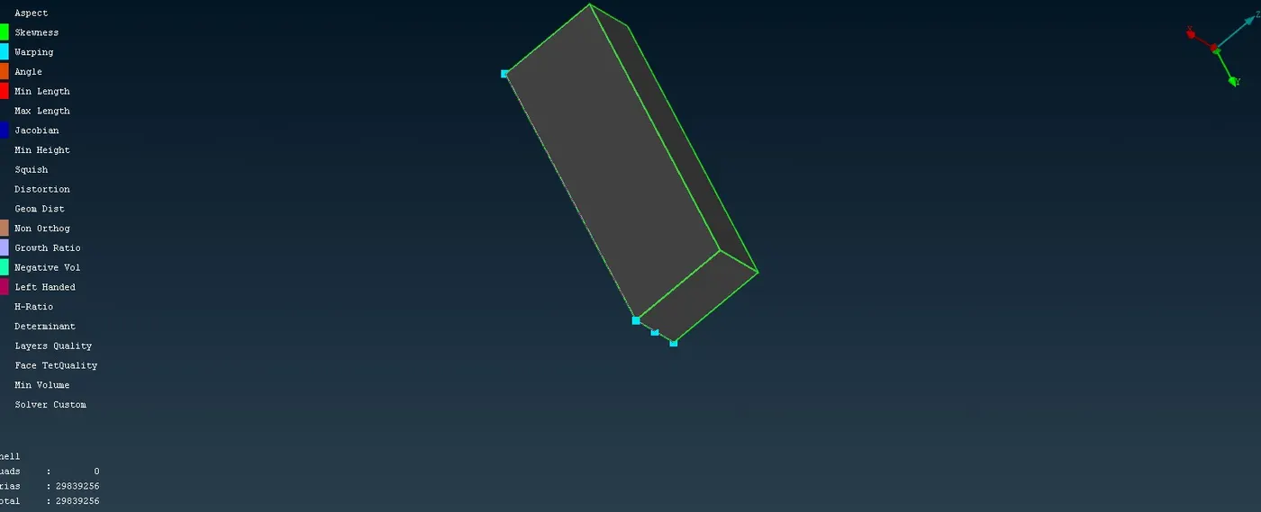
As a result of surface meshing,29.8 million Triangular elements are created.
Conclusion:
Geometry cleanup and Surface meshing for cybertruck tesla are created successfully.
Meshed model is attached in a Zip format https://drive.google.com/file/d/1GDsACFQf6xN5AiCjkFhhGbKEySsjPzkC/view?usp=drive_link