Project 1 : CFD Meshing for Tesla Cyber Truck
CFD MESHING FOR TESLA CYBER TRUCK
AIM / OBJECTIVE:
For the given model
- Check and solve all geometrical errors.
- Assign appropriate PIDs.
- Perform meshing with the suitable Target length and element Quality criteria.
- Create a wind tunnel and do the surface meshing of wind tunnel.
GIVEN:
Target length for the different PIDs are as follows:
- Tyres - 2mm
- Windows - 2mm
- Body - 3mm
- Lights - 4mm
Quality Criteria for Tesla Cyber Truck:
- Skewness - 0.7
- Min Length - 0.1
- Max Length - 10
BASIC STEPS TO BE FOLLOWED WHILE STARTING THE ANSA
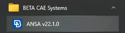
Click on the ANSA v22.1.0 in the Start Menu to open the ANSA software.
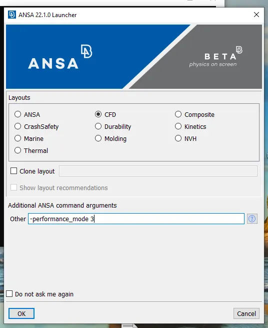
After clicking the ANSA v22.1.0 the above window pops up. In the above poped up window, select the CFD in Layouts.
In additional ANSA command arguments change the other to -performance_mode 3
Always remember not to click/tick on Dont ask me again. Finally click the OK button.
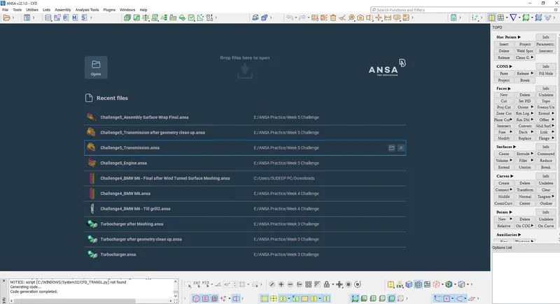
After opening the above window, right click on the top tab with icons and select the show labels and click apply to all.
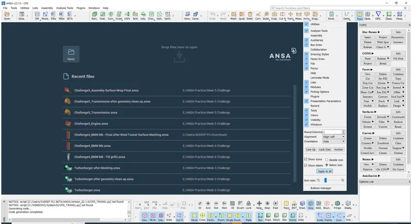
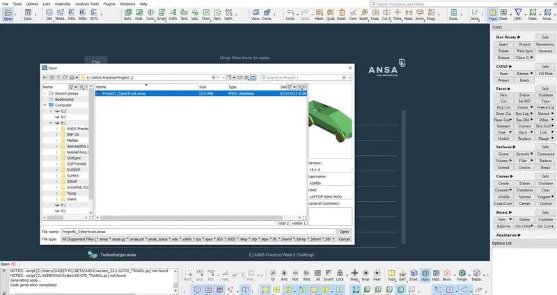
Open the downloaded Project1_Cybertruck.ansa file as shown below.
The above file is opened in wireframe mode as shown below.
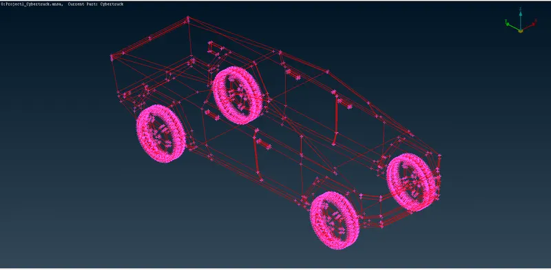
On opening the model you see the Red cons or Double cons as shown in the above image.
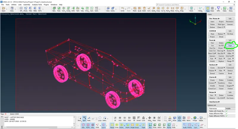
Select Topo under CONS in TOPO, left click and drag the mouse to make a selection box.
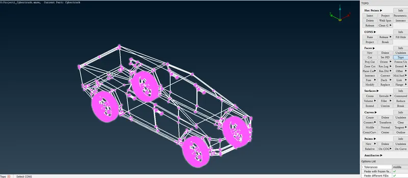
After selection as shown in the above image, press the middle mouse / scroll button.
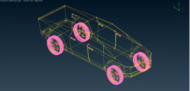
After doing Topo you can see that majority of the Red cons are resolved, except for few as shown in the above figure.
Now I attempt to resolve the remaining red cons.
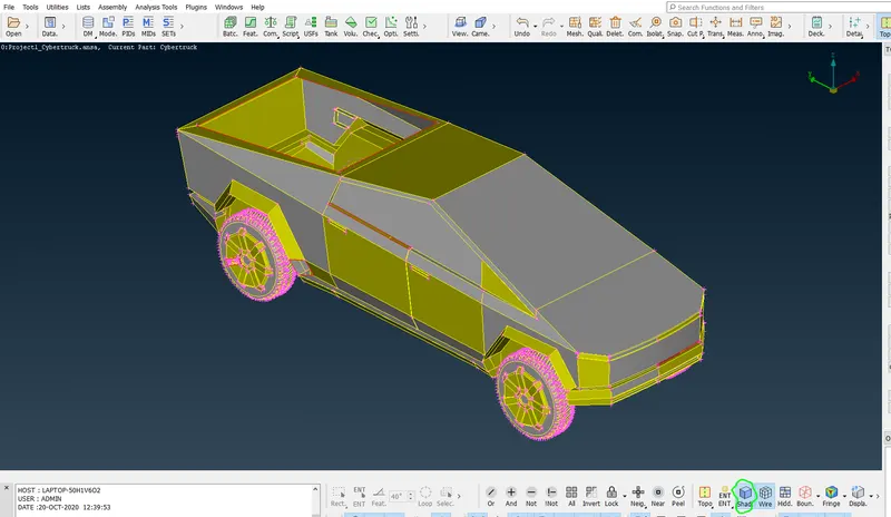
Turn on the shading mode by using the green encicled button as shown in the above figure.
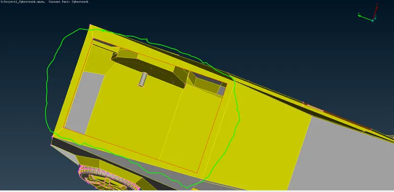
I attempt to resolve the red cons encircled in the green as shown in the above image.
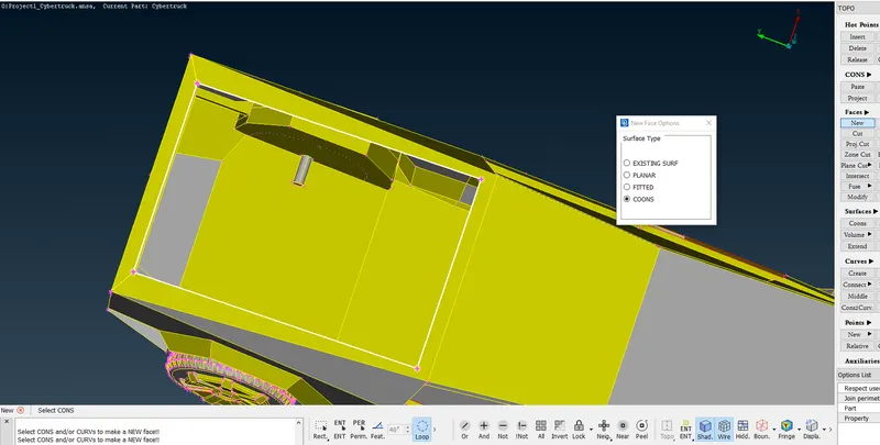
A new face is created by the selection made as shown in the above image using New under Faces in TOPO.
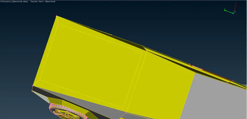
Red cons attempted is resolved.
Now I attempt to resolve the red cons in green encirled portion as shown in the below image.
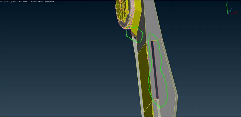
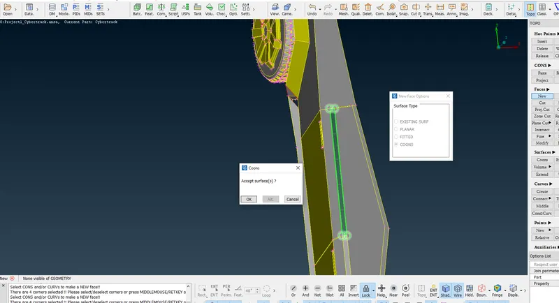
A new face is created by the selection made as shown in the above image using New under Faces in TOPO.
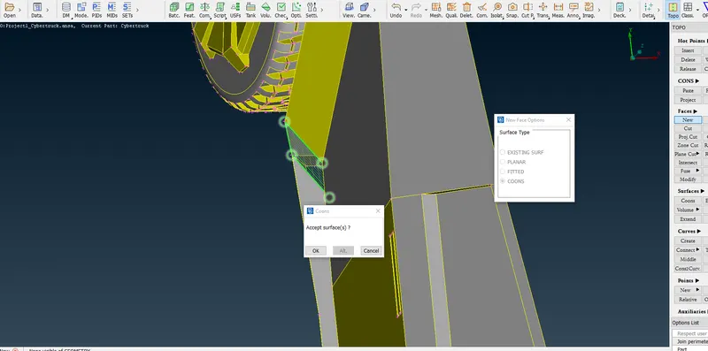
A new face is created by the selection made as shown in the above image using New under Faces in TOPO.
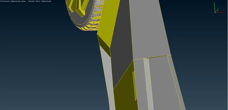
Red cons attempted are resolved.
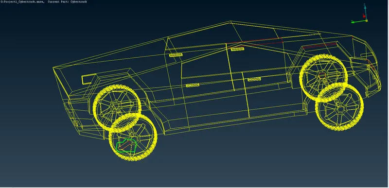
I attempt to resolve the red cons encirled in green at one of the tyres as shown in the above image.
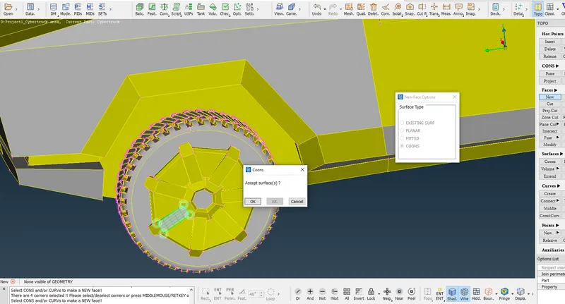
A new face is created by the selection made as shown in the above image using New under Faces in TOPO.
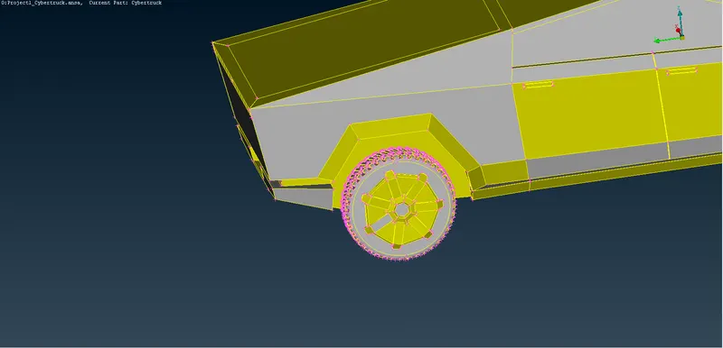
Red cons attempted are resolved.
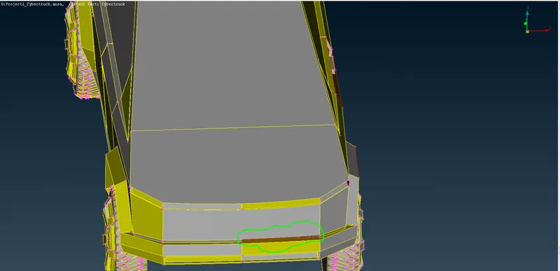
I attempt to resolve the red cons in green encirled portion as shown in the above image.
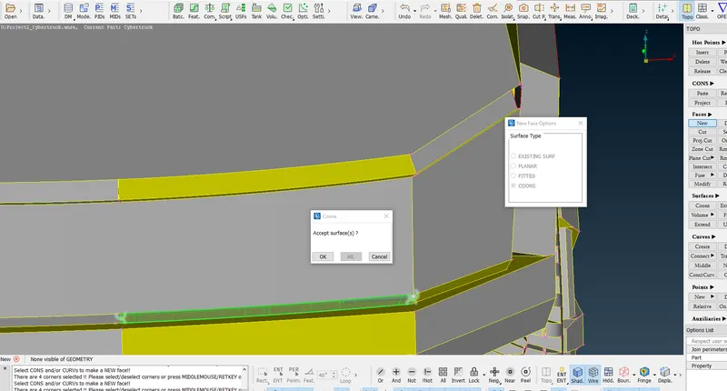
A new face is created by the selection made as shown in the above image using New under Faces in TOPO.
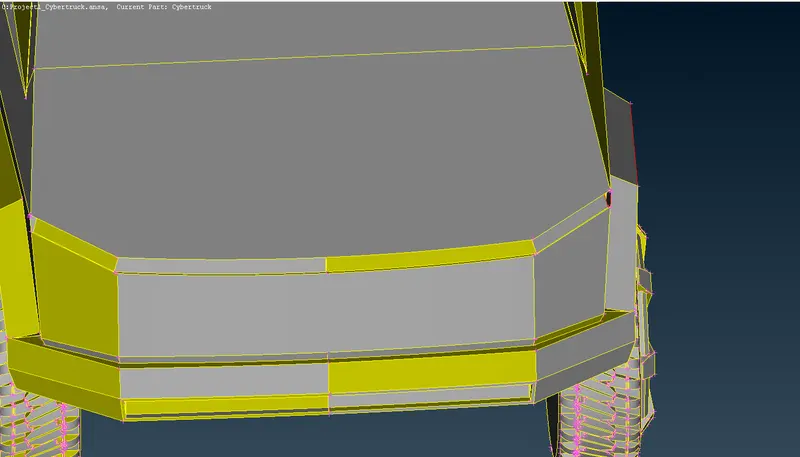
Red con attempted is resolved.
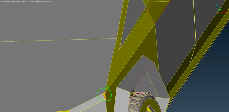
I attempt to resolve the red cons in green encirled portion as shown in the above image.
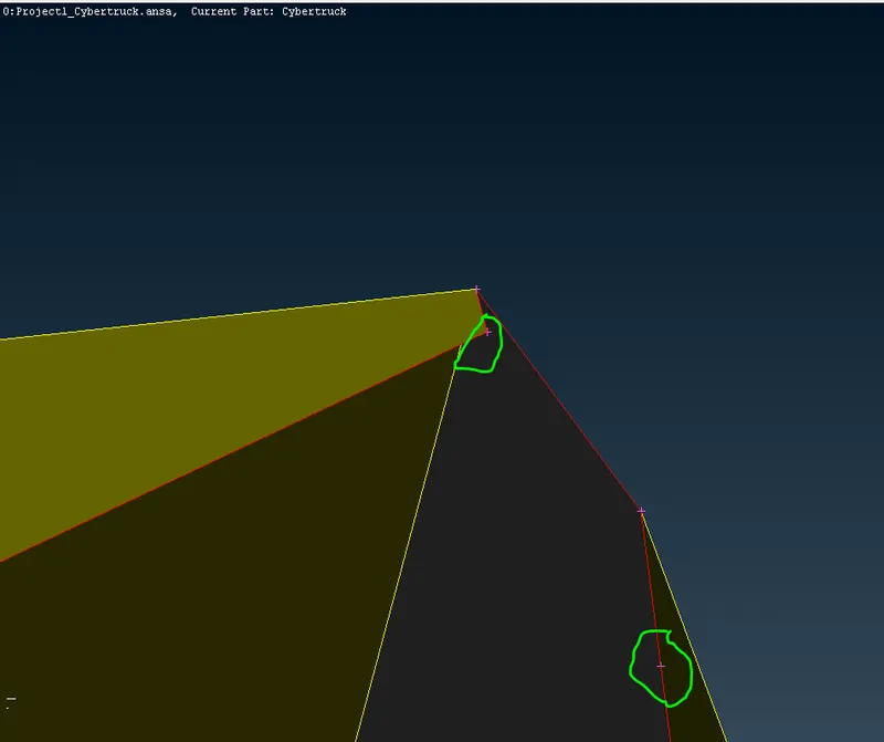
On zooming we see there are unnecessary extra hot points. The hot points are deleted using Delete under Hot Points in TOPO.
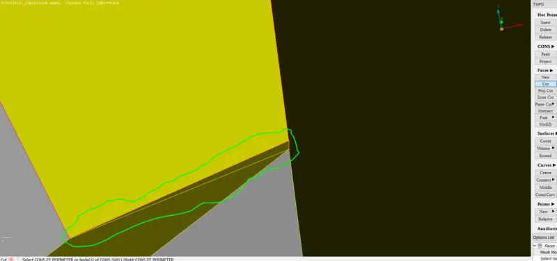
A cut is created as shown in the green encircled portion as shown in the above image.
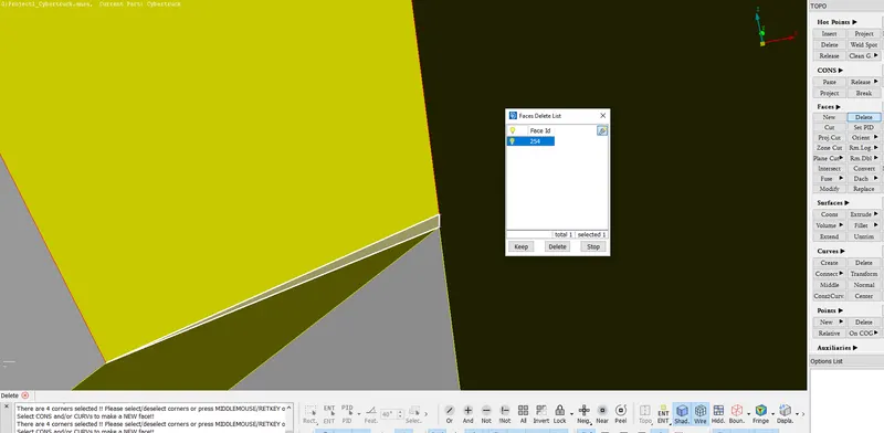
The selected surface as shown in the above image is deleted as it is not required.
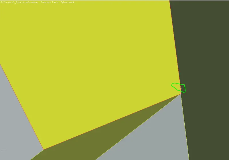
An unnecessary extra hot point encircled in green is deleted using Delete under Hot Points in TOPO.
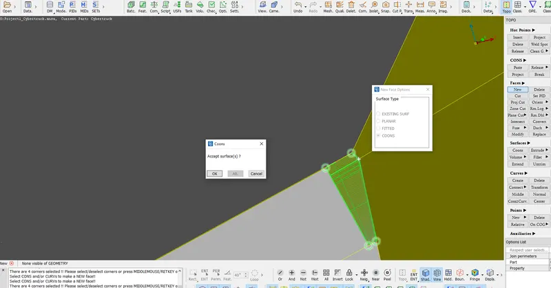
A new surface is created using New under Faces in TOPO as shown in the above image.
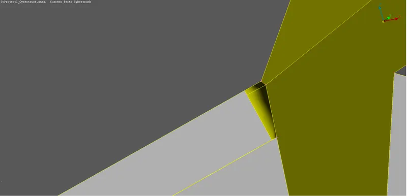
Red con attempted is resolved.
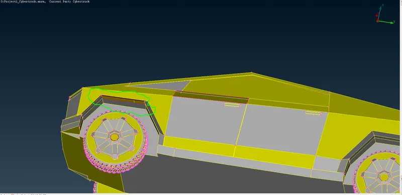
I attempt to resolve the red cons in green encirled portion as shown in the above image.
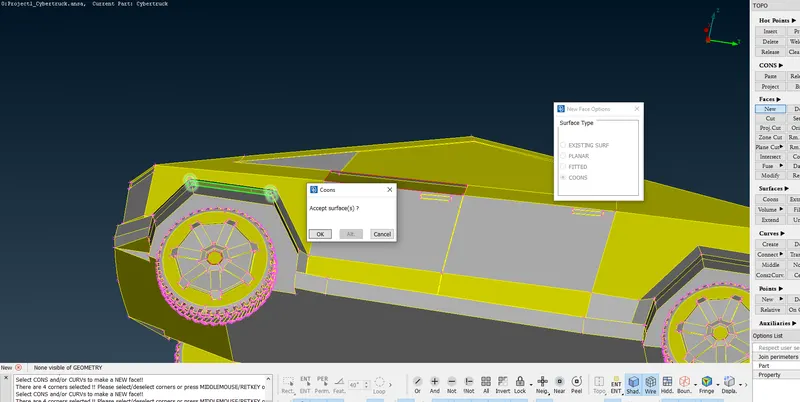
A new face is created using New under Faces in TOPO as shown in the above figure. Red con attempted is resolved.
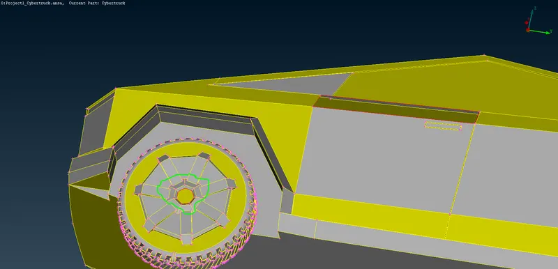
I attempt to resolve the red cons in green encirled portion as shown in the above image.
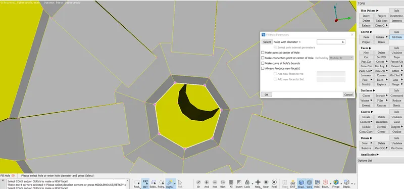
Using Fill Hole, a face is created in the red con present area.
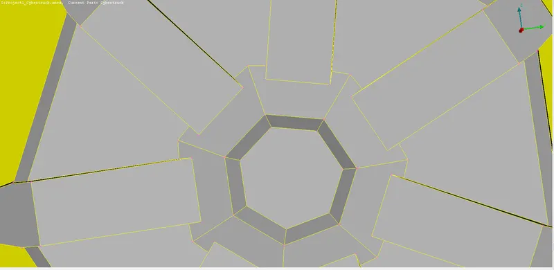
Red con attempted is resolved.
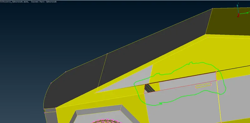
I attempt to resolve the red cons in green encirled portion as shown in the above image.
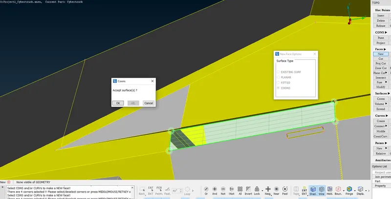
A new face is created using New under Faces in TOPO as shown in the above figure.
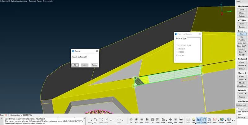
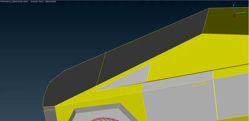
Red con attempted is resolved.
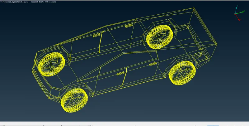
In wieframe mode, by just viewing I see that there are no red cons present visible as shown in the above image.
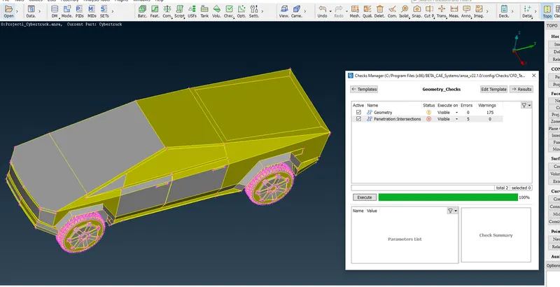
The geometry check using Checks Manager is done and found that there are 5 intersection errors which needs to be resolved.
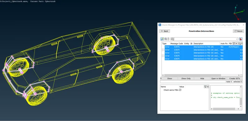
In the above image, the area of intersection can be seen. A check need to be done o identify the cause of intersection error.
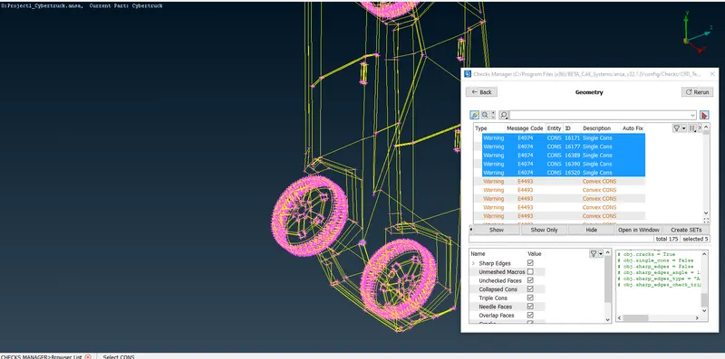
Also few single cons in the highlighted region is present as an warnings in Geometry which needs to be taken care.
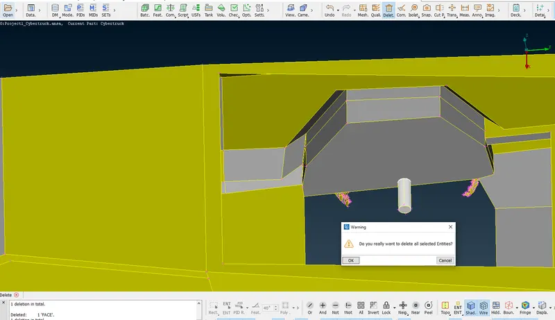
After careful observation using Not option I was able to find out one reason for intersection error was the shaft of tyre with the body.
The shaft has been deleted using universal delete. After deleteting the shaft red cons are generated where the shaft was intersecting the body.
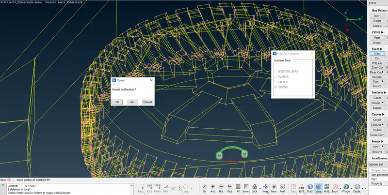
A surface is created using New under Faces in TOPO and then clicking the entity and selecting the curves.
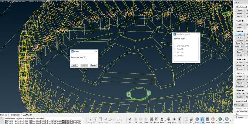
A surface is created using New under Faces in TOPO and then clicking the loop and selecting the curves.
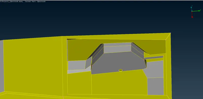
Red cons generated has been resolved.
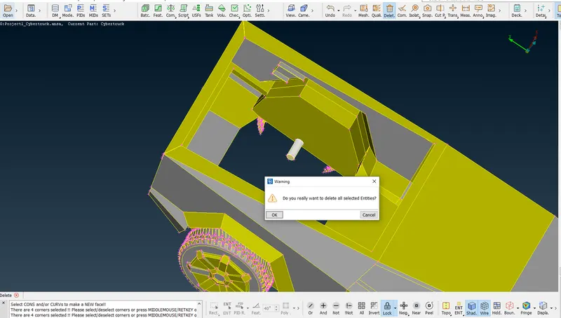
The shaft has been deleted using universal delete. After deleteting the shaft red cons are generated where the shaft was intersecting the body.
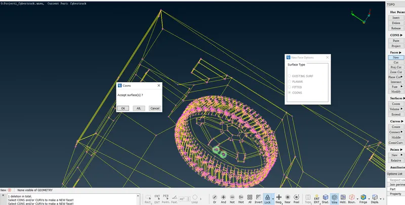
A surface is created using New under Faces in TOPO and then clicking the entity and selecting the curves.
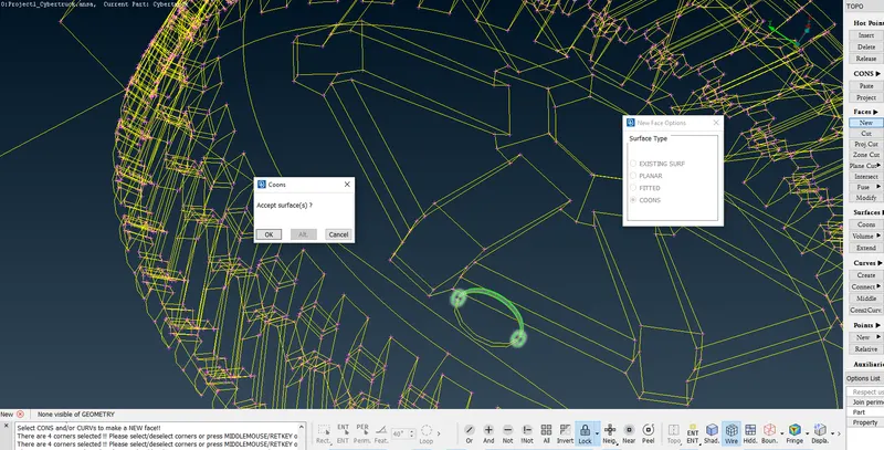
A surface is created using New under Faces in TOPO and then clicking the loop and selecting the curves.
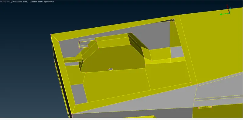
Red cons generated has been resolved.
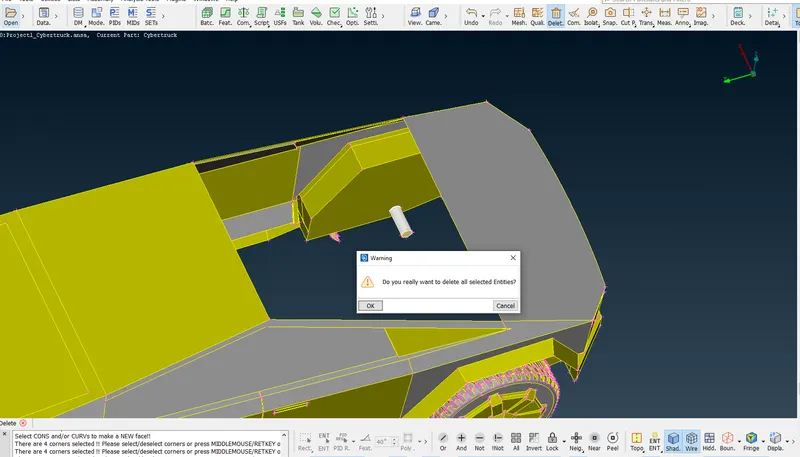
The shaft has been deleted using universal delete. After deleteting the shaft red cons are generated where the shaft was intersecting the body.
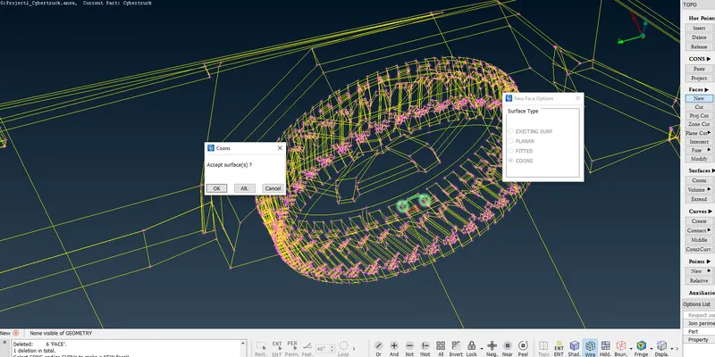
A surface is created using New under Faces in TOPO and then clicking the entity and selecting the curves.
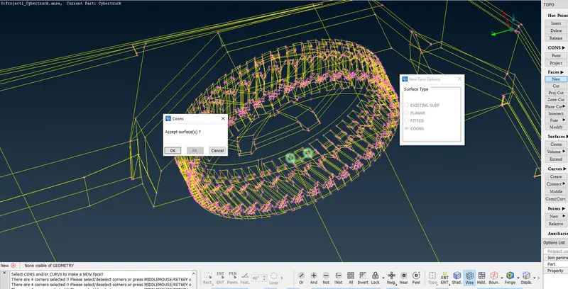
A surface is created using New under Faces in TOPO and then clicking the loop and selecting the curves.
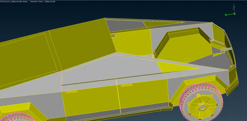
Red cons generated has been resolved.
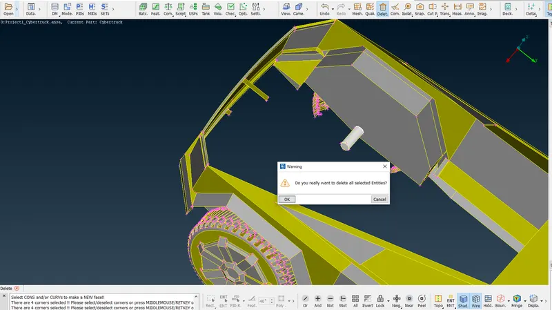
The shaft has been deleted using universal delete. After deleteting the shaft red cons are generated where the shaft was intersecting the body.
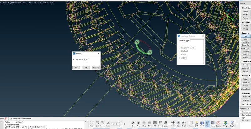
A surface is created using New under Faces in TOPO and then clicking the entity and selecting the curves.
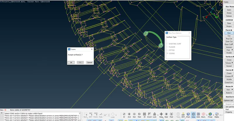
A surface is created using New under Faces in TOPO and then clicking the loop and selecting the curves.
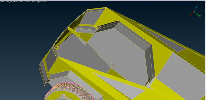
Red cons generated has been resolved.
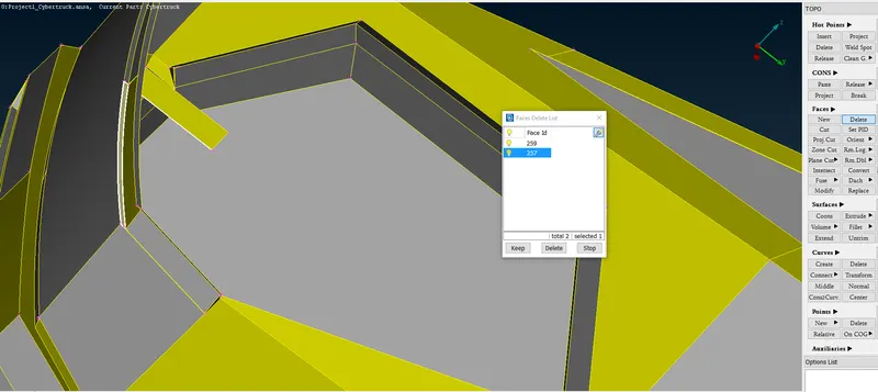
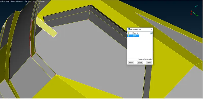
An undesired surface as shown in the above image is deleted.
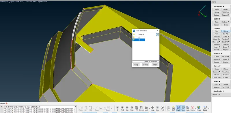
An undesired surface as shown in the above image is deleted.
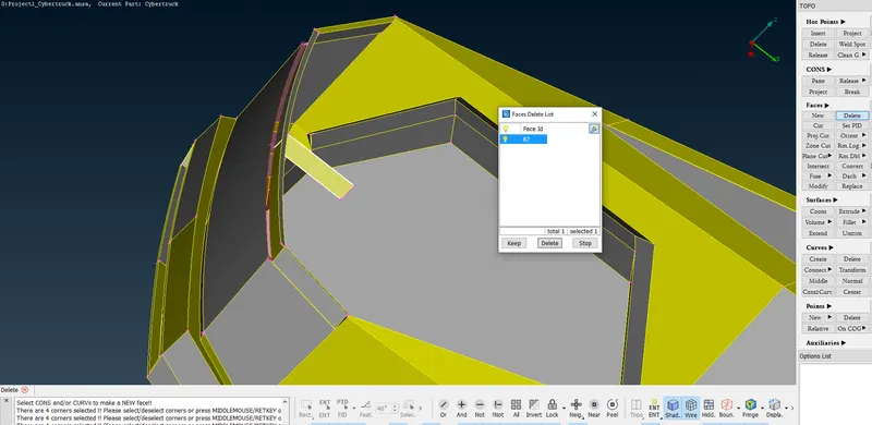
An undesired surface as shown in the above image is deleted.
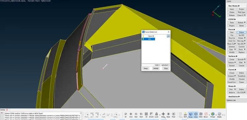
An undesired surface as shown in the above image is deleted.
An undesired surface as shown in the above image is deleted.
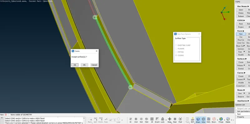
A new face is created using the New under Face in TOPO.
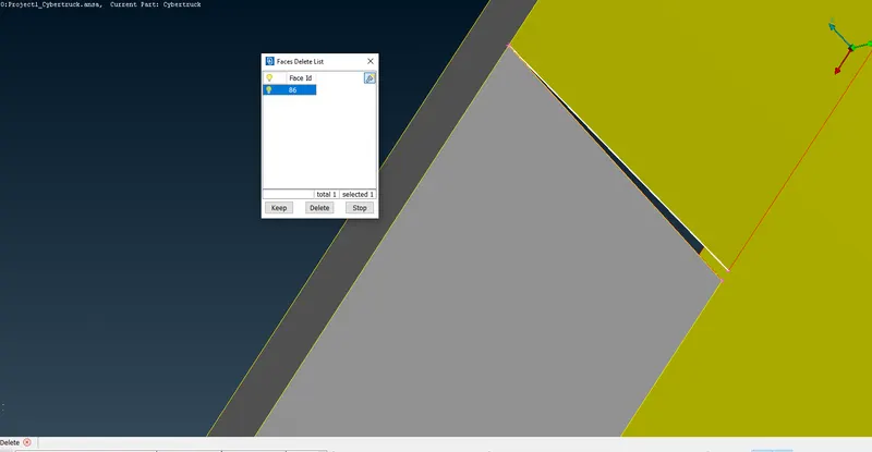
The surfaces selected in the above image is deleted as this is not required.
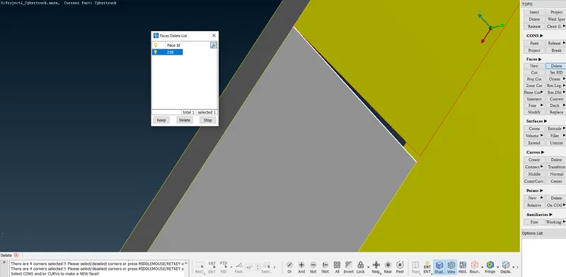
The surfaces selected in the above image is deleted as this is not required.
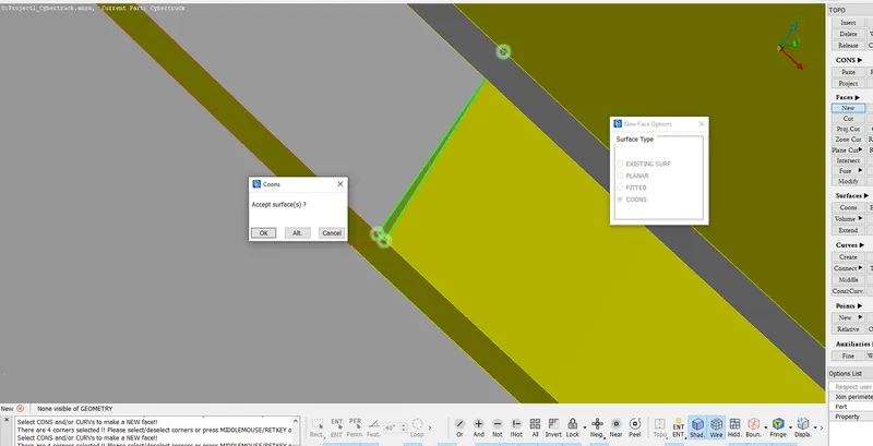
The new face is created using New under Faces in TOPO to resolve the red cons generated due to deletion of surfaces.
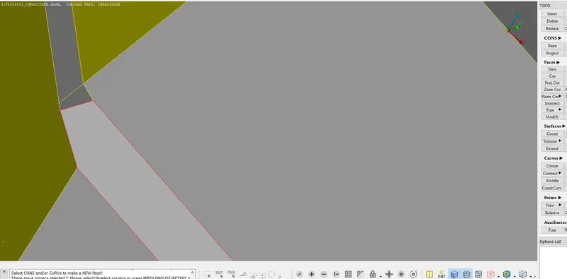
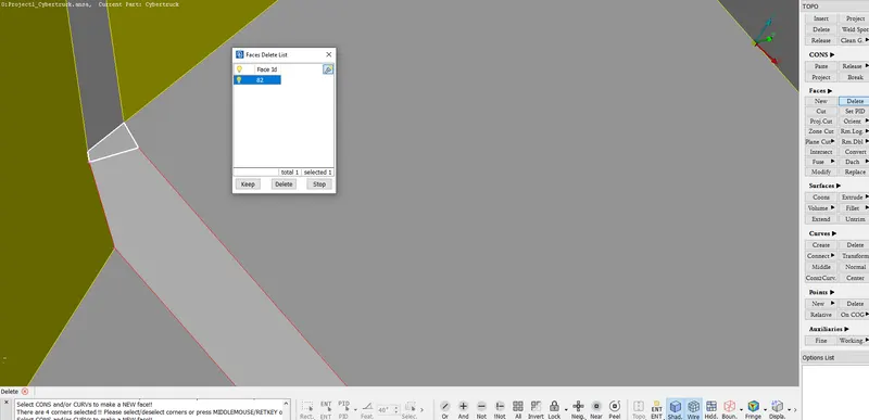
The face seleted in the above image is deleted.
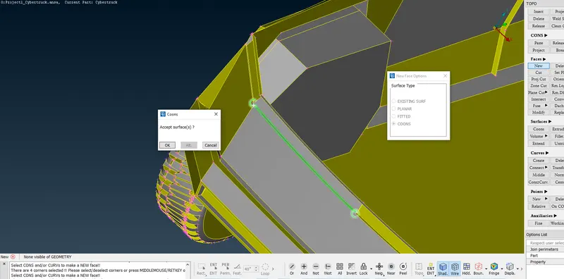
A new face is generated using the New under Faces in TOPO.
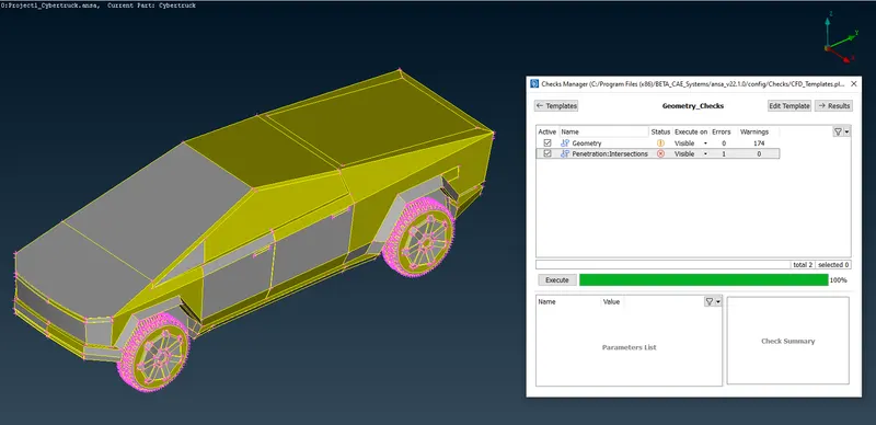
I do the geometry check using the Checks Manager.
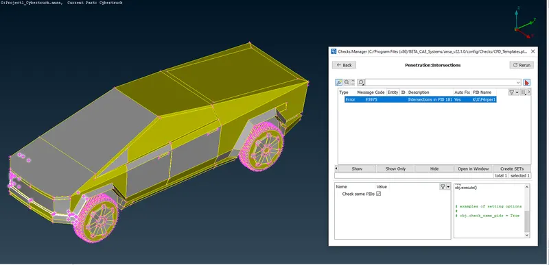
One intersection error is encountered as shown and highlighted in the above image.
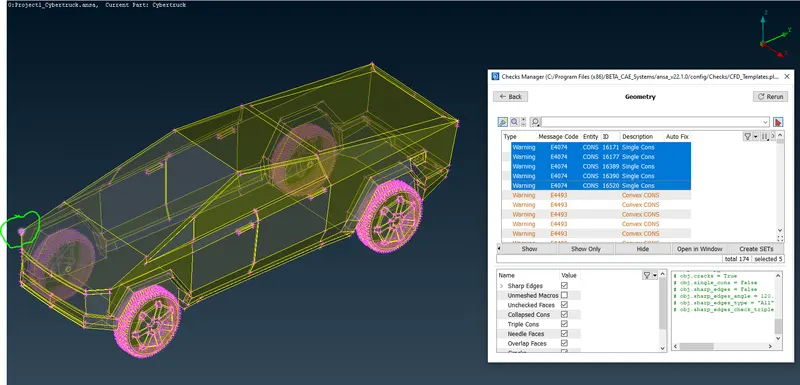
Also there is single cons highted in the geometry warnings as shown in the above image.
I attempt to resolve the single cons.
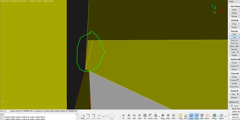
I create a cut using the Cut under Faces in TOPO as shown in the green encircled portion.
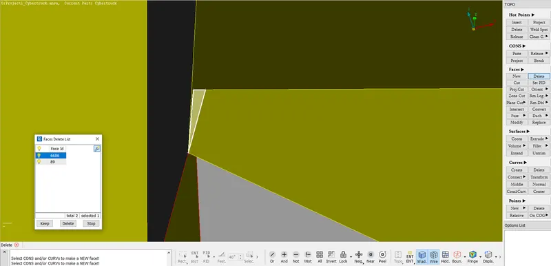
The cut surface as shown in the above image is deleted as this is not required.
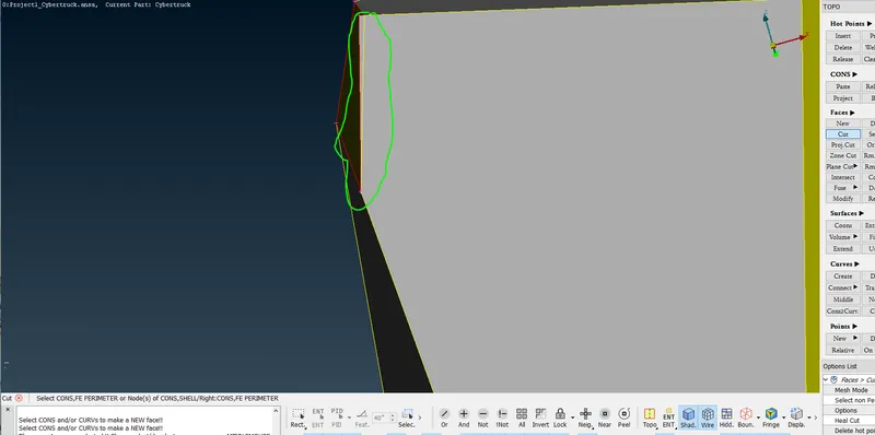
I create a cut using the Cut under Faces in TOPO as shown in the green encircled portion.
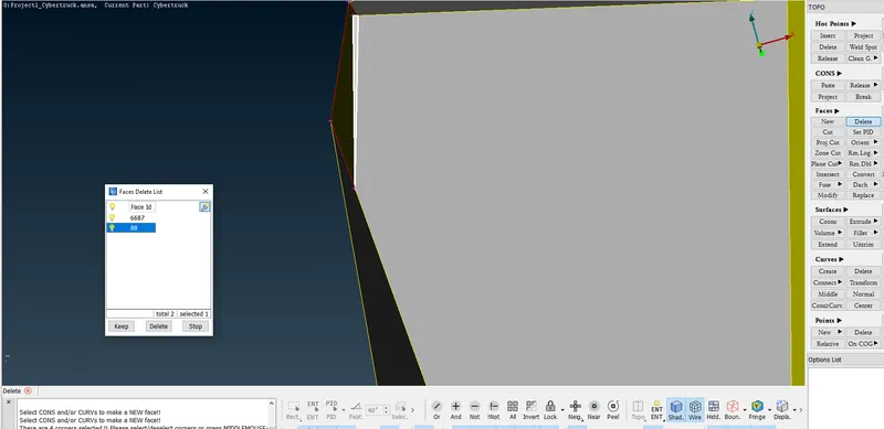
The cut surface as shown in the above image is deleted as this is not required.
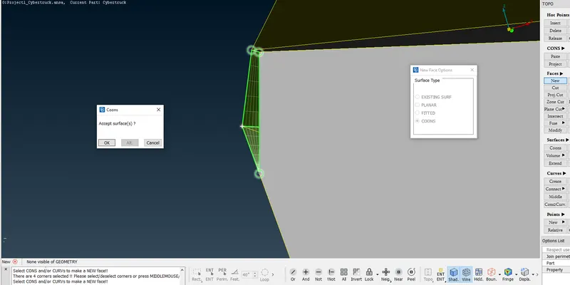
New surface is created using New under faces in TOPO.
Finally the red cons attempted are resolved.
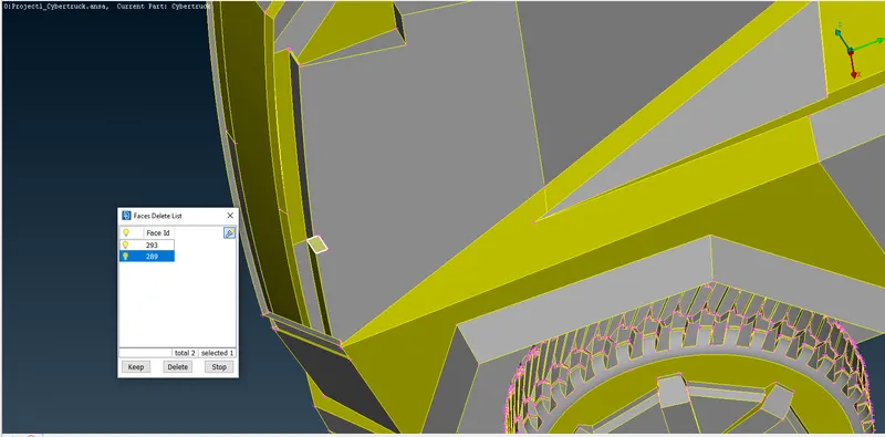
The selected surface is not required hence it is deleted.
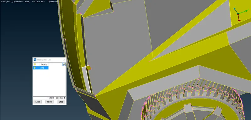
The selected surface is not required hence it is deleted.
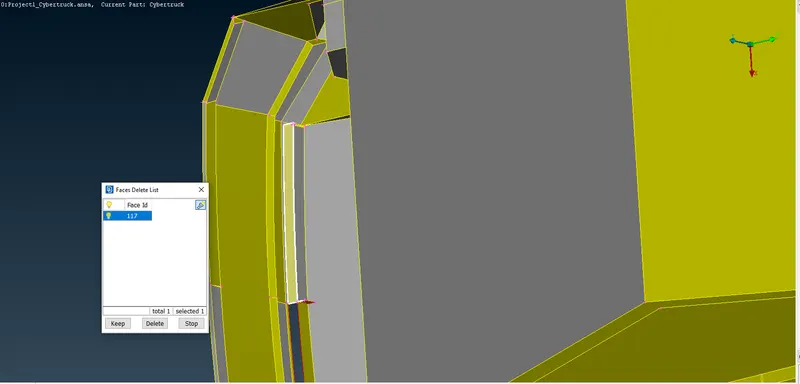
The selected surface is not required hence it is deleted.
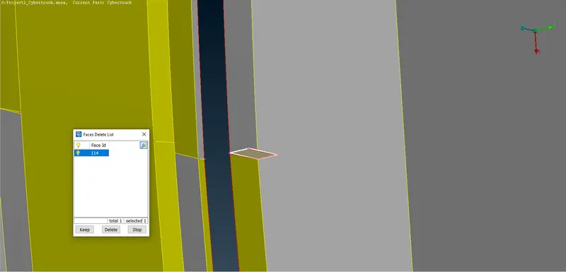
The selected surface is not required hence it is deleted.
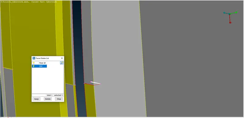
The selected surface is not required hence it is deleted.
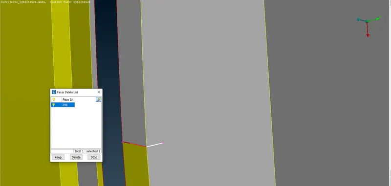
The selected surface is not required hence it is deleted.
Now I attempt to resolve the intersection error present in the geometry.
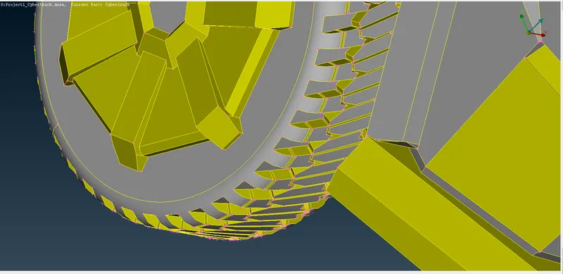
The intersection is at the tyre guard and body.
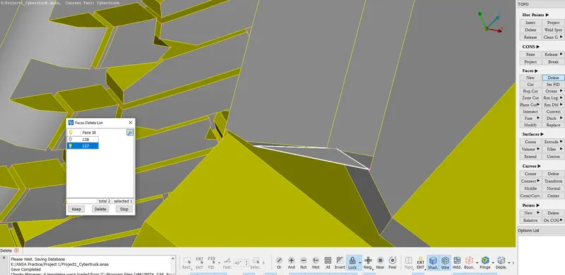
The selected surface ashown in the above image is deleted using Delete under Faces in TOPO.
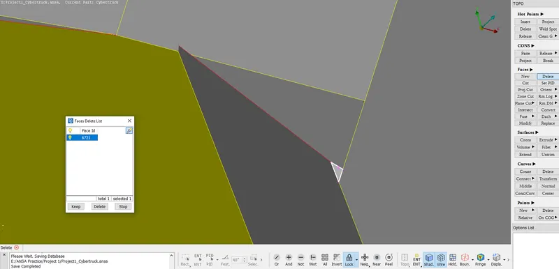
A cut is created and the selected surface is deleted as this is not required.
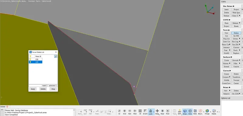
The selected surface is deleted as this is not required.
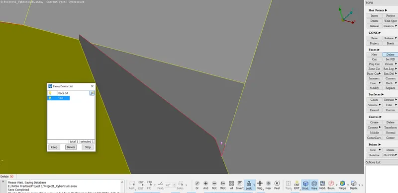
The selected surface is deleted as this is not required.
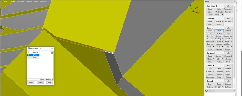
The selected surface is deleted as this is not required.
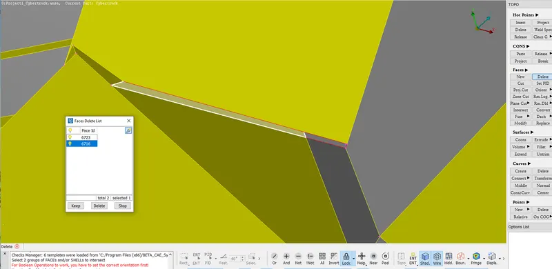
The selected surface is deleted as this is not required.
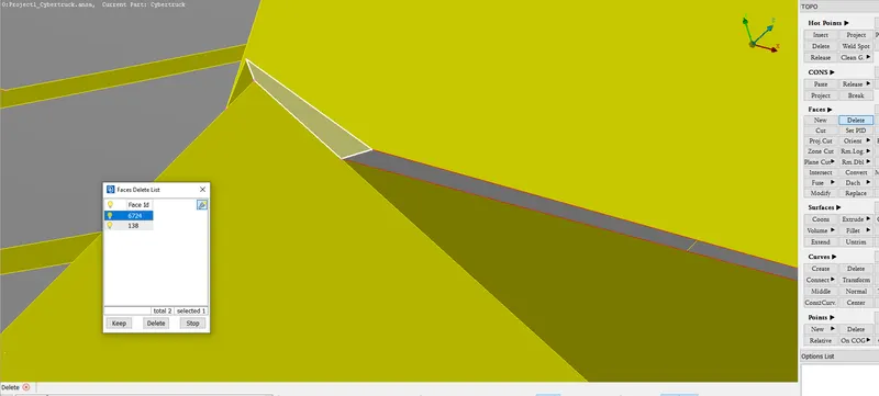
The selected surface is deleted as this is not required.
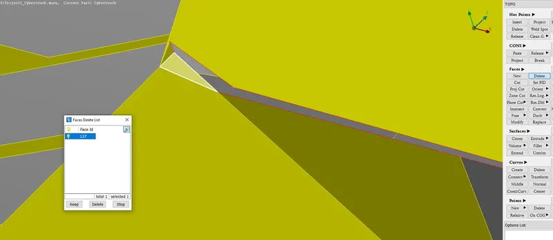
The selected surface is deleted as this is not required.

The selected surface is deleted as this is not required.
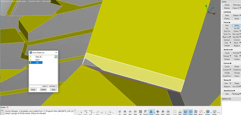
The selected surface is deleted as this is not required and to create a better face.
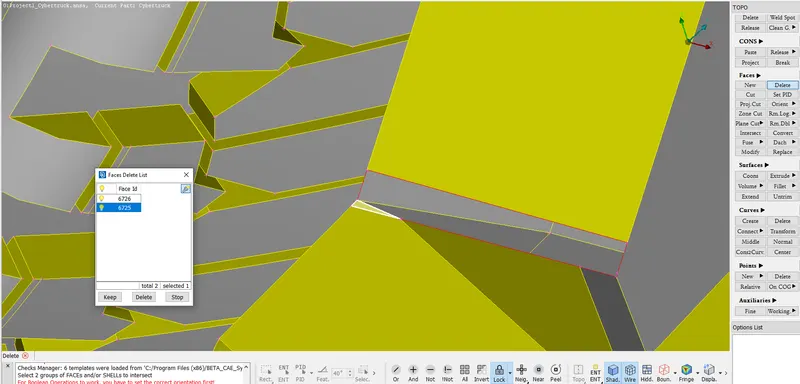
The selected surface is deleted as this is not required.
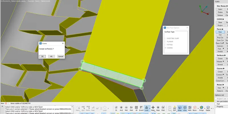
A new face is created as shown in the above image.
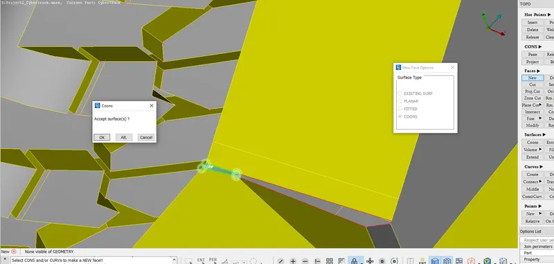
A new face is created as shown in the above image.
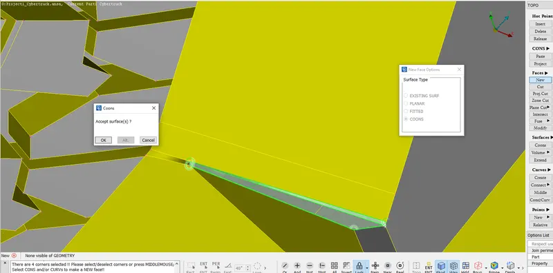
A new face is created as shown in the above image.
Similar procedure of creating a cut, deleting the faces and creating new faces to resolve the intersection error at the other front end of Tesla Cyber Truck.
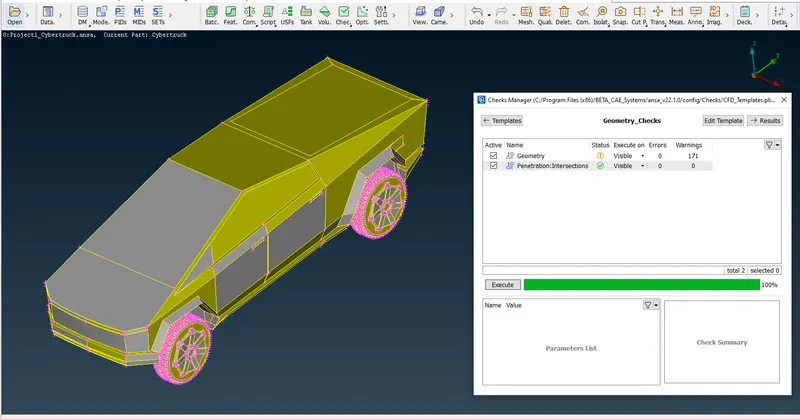
Now I perform the geometry check using the Checks Manager and found no errors.
The geometry clean up of the Tesla Cyber truck is done successfully.
Now we assign the PIDs.
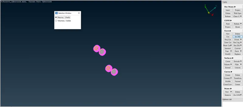
Using !Not option the tyres are isolated. Using Set PID under Faces in TOPO PID is assigned.
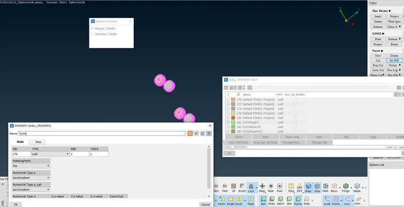
Using the methodology as shown in the above image the PID named Tyres is assigned.
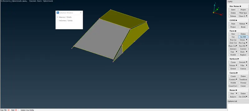
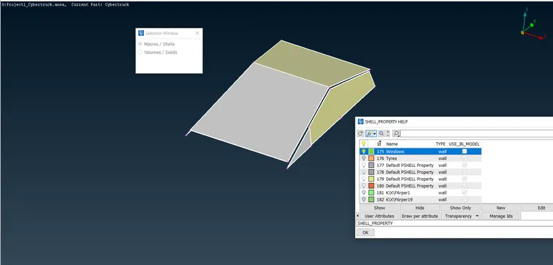
Using !Not option the windows are isolated. Using Set PID under Faces in TOPO PID is assigned.
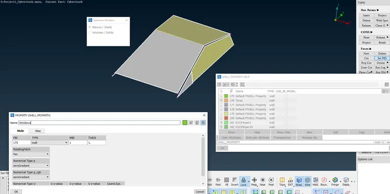
Using the methodology as shown in the above image the PID named Windows is assigned.
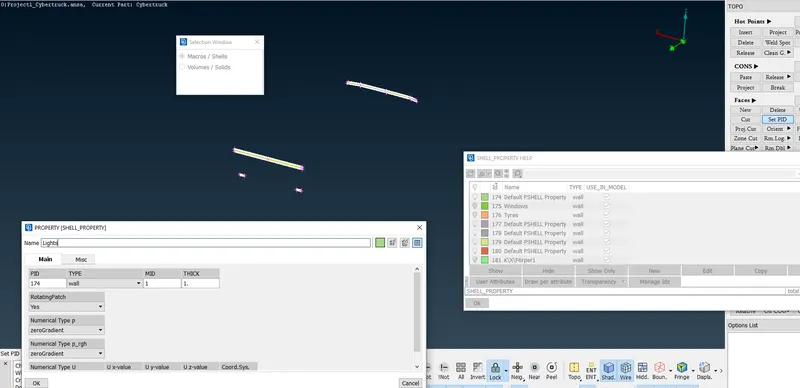
Using !Not option the lights are isolated. Using Set PID under Faces in TOPO PID is assigned.
Using the methodology as shown in the above image the PID named Lights is assigned.
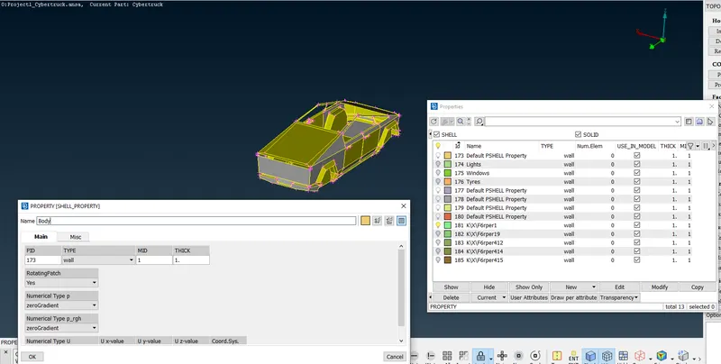
Using All option everything appears. The properties PID Manager is used to isolate the Body as shown in the above image.
Using the methodology as shown in the above image the PID named Body is assigned.
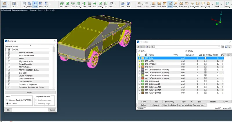
Using the Compress option the unassigned and unused default PIDs are deleted.
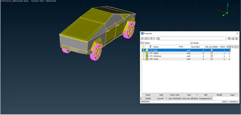
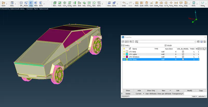
The final PIDs assigned for the Tesla Cyber Truck geometry in PID mode.
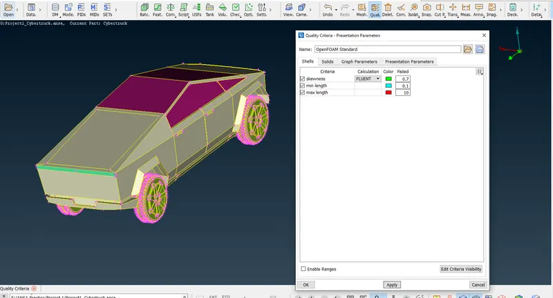
Using the procedure as shown in the above image we set the Quality Criteria for Tesla Cyber Truck.
First I attempt the CFD Meshing of the body. The Target Length for Body is 3mm.
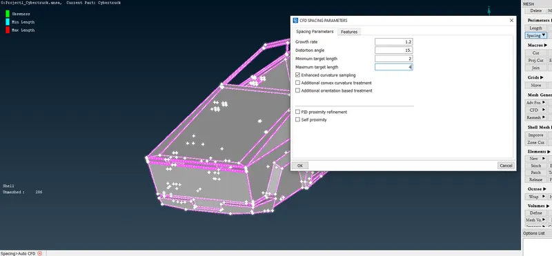
Using Spacing under Perimeters in Auto CFD we set Minimum and Maximum Target Length as shown in the above image.
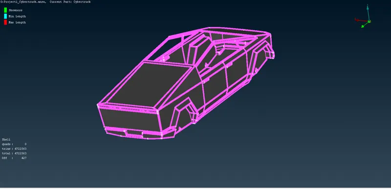
CFD meshing is done. Off elements are seen as shown in the above image.
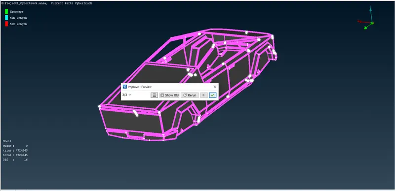
Using Reconstruct under Improve the Off elements are reduced.
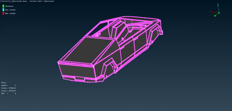
Using Reshape under Improve the Off elements are reduced.
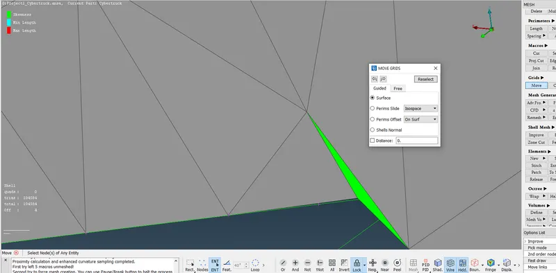
Using Move under Grids in MESH the Off element failing the skewness criteria is resolved.
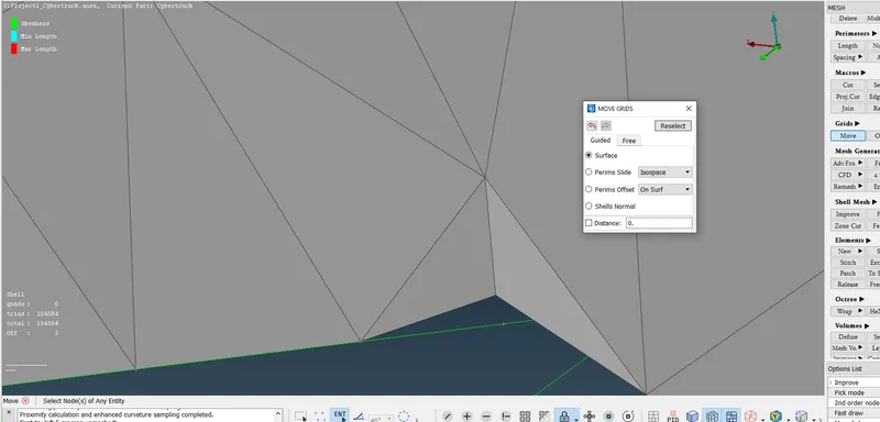
Off element is reduced.
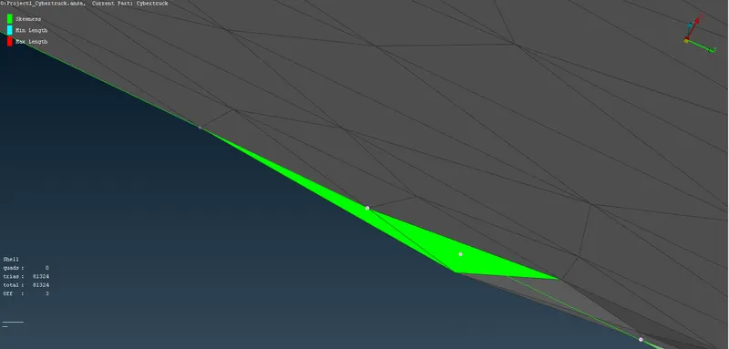
Using Move under Grids in MESH the Off element failing the skewness criteria is resolved.
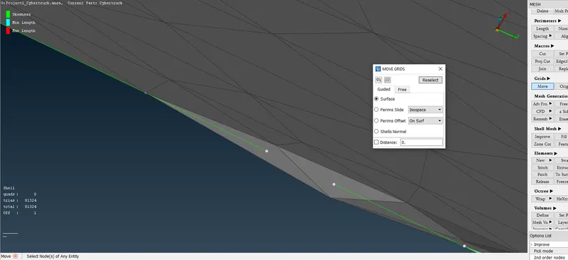
Off element is reduced to one.
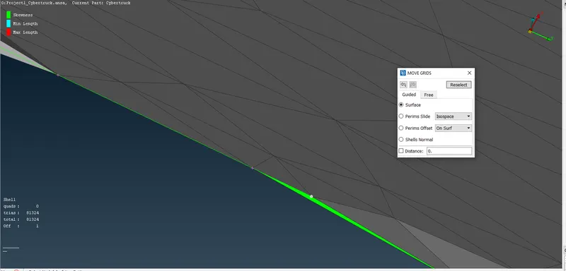
After careful observation the remaining one element is spotted which is highly skewed as shown in the above image.
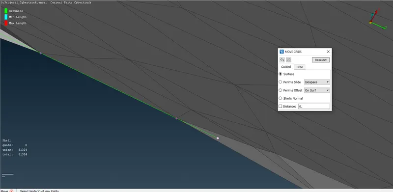
Using Move under Grids in MESH the Off element failing the skewness criteria is resolved. 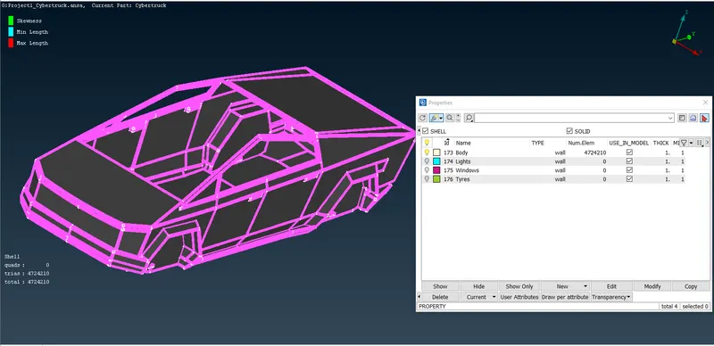
All the Off elements for Body are resolved.
Now I attempt the CFD Meshing of the Windows. The Target Length for Windows is 2mm.
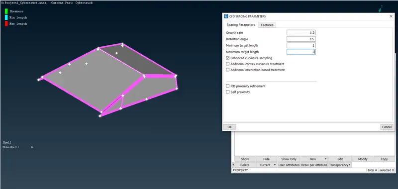
The Target length for Windows is 2mm.
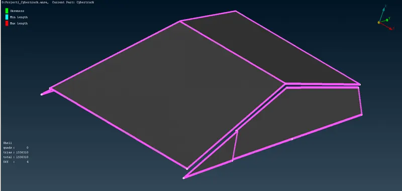
CFD meshing is done. Off elements are seen as shown in the above image.
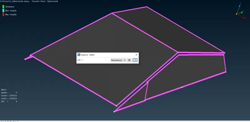
Using Reconstruct under Improve as shown in the above image we attempt to resolve the Off elements.
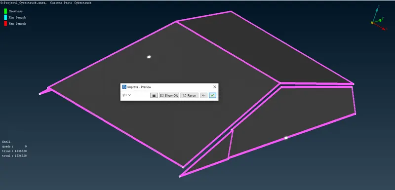
The off elements are resolved.
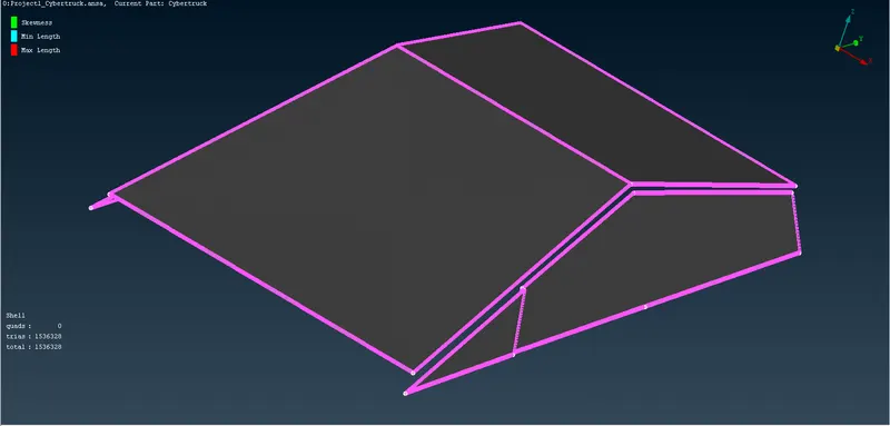
All the Off elements for Body are resolved.
Now I attempt the CFD Meshing of the Lights.
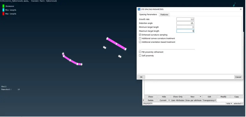
The Target Length for Lights is 4mm.
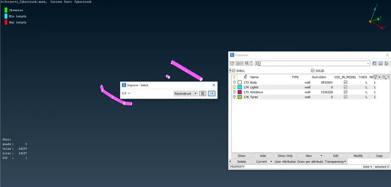
CFD Meshing is done. Off element found is resolved using Reconstruct under Improve.
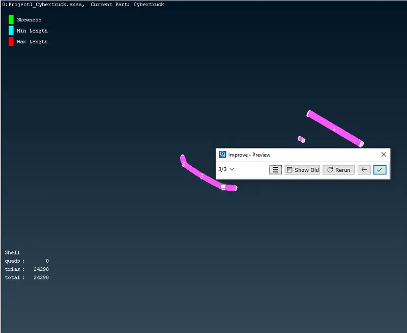
The Off elements for Lights is resolved.
Now I attempt the CFD Meshing of the Tyres.
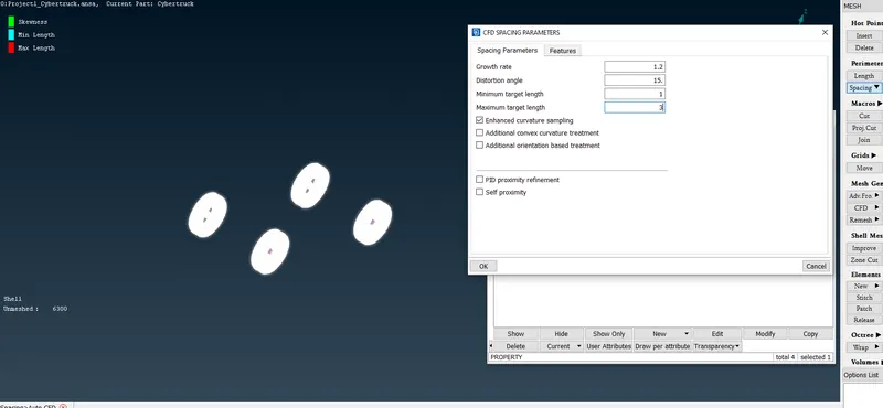
The Target Length for Tyres is 2mm.
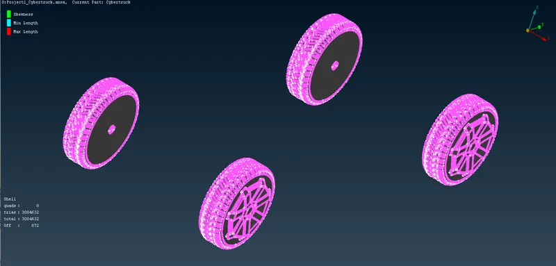
CFD meshing is done. Off elements are found as shown in the above image.
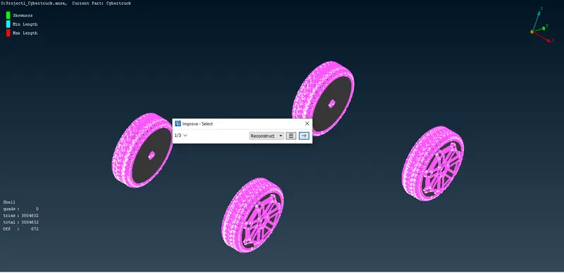
Reconstruct under Improve is used to resolve the off elements.
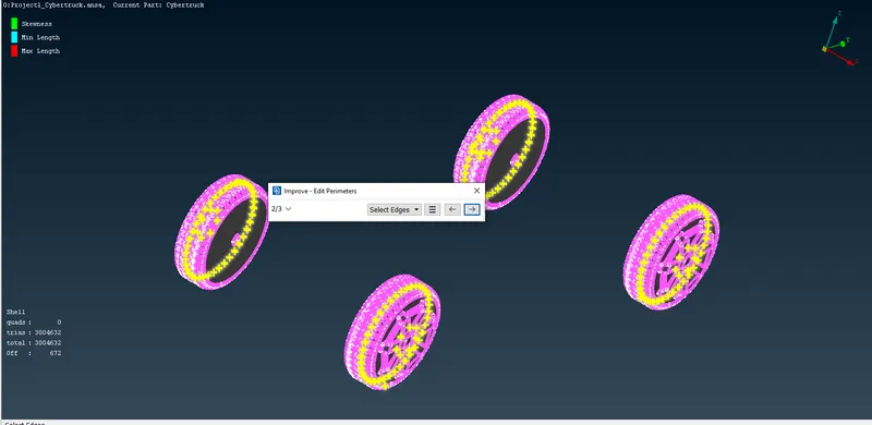
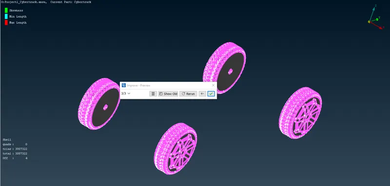
Off elements has been reduced.
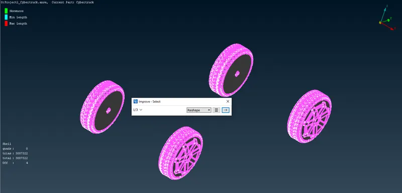
Now Reshape under Improve is used to further resolve the Off elements.
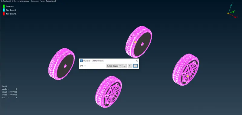
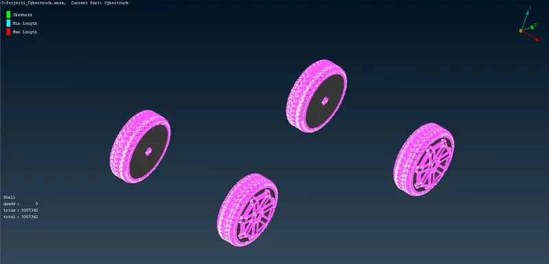
All the off elements for Tyres are resolved successfully.
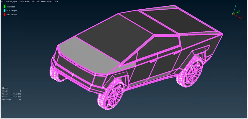
After All is used some unmeshed elements are seen as seen in the above image. Using Free under Mesh Generation in MESH, meshing for the unmeshed surfaces are done.
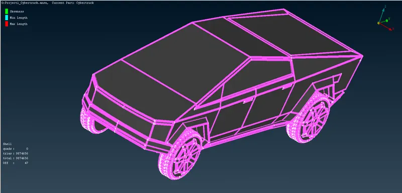
Off elements are seen.
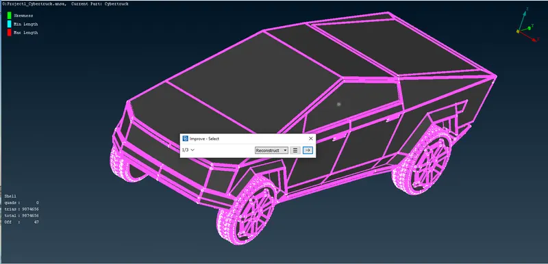
Using Reconstruct under Improve, an attempt is made to resolve the Off elements.
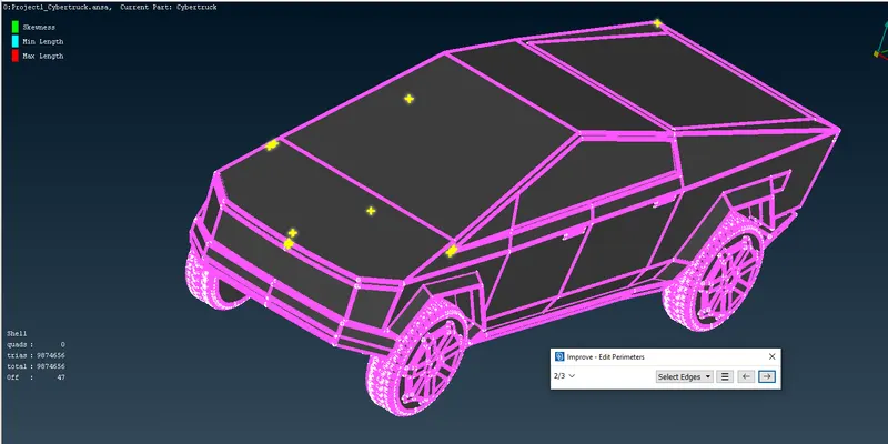
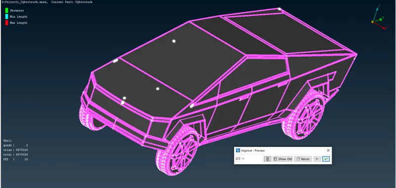
Off elements are reduced as shown in the above image.
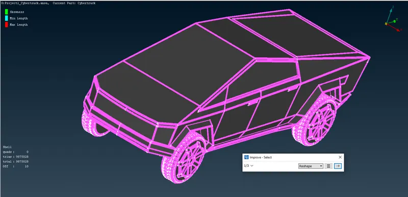
Using Reshape under Improve, an attempt is made to resolve the balance Off elements.
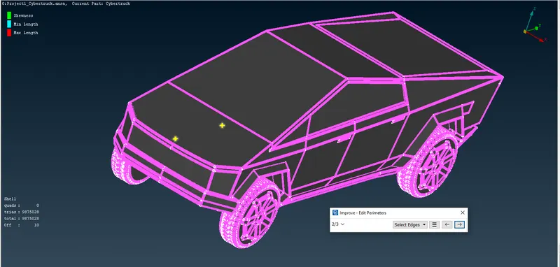
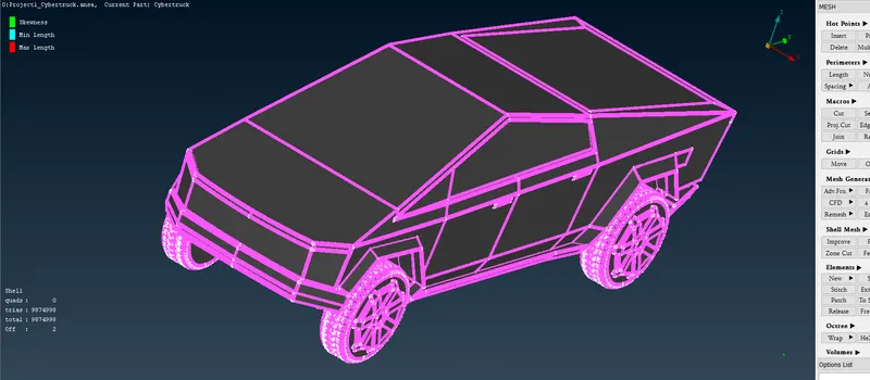
Off elements are reduced to two.
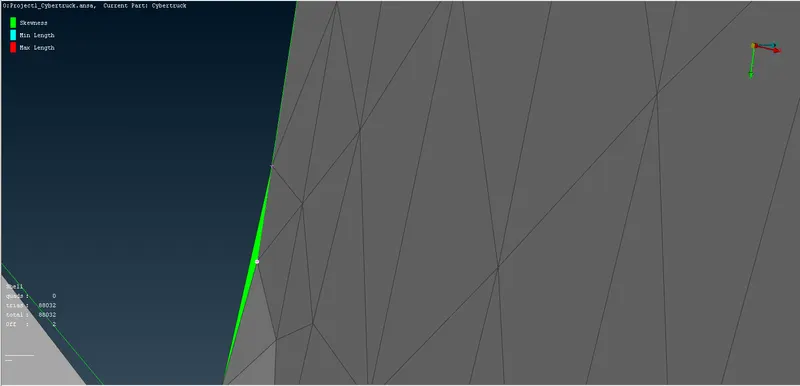
One of the two highly skewed element is located as shown in the above image.
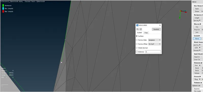
Using the Move under Grids in Mesh the located off element is resolved.
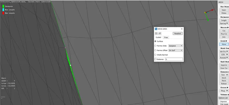
The remaining last Off element is located as shown in the above image. It is also a highly skewed element.
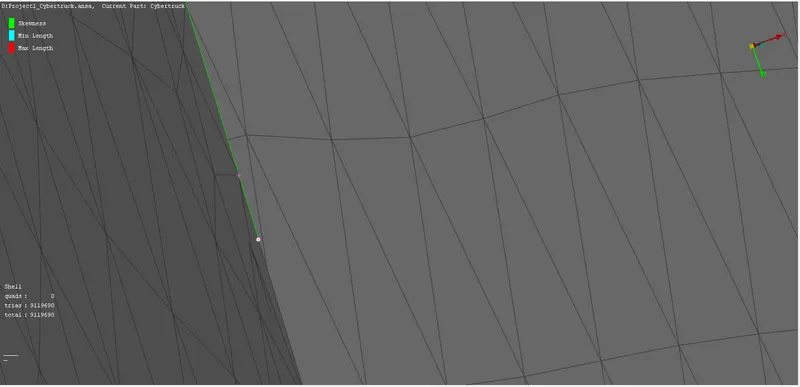
Using the Move under Grids in Mesh the located off element is resolved.
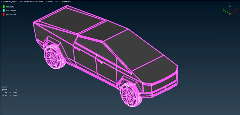
All the off elements are resolved.
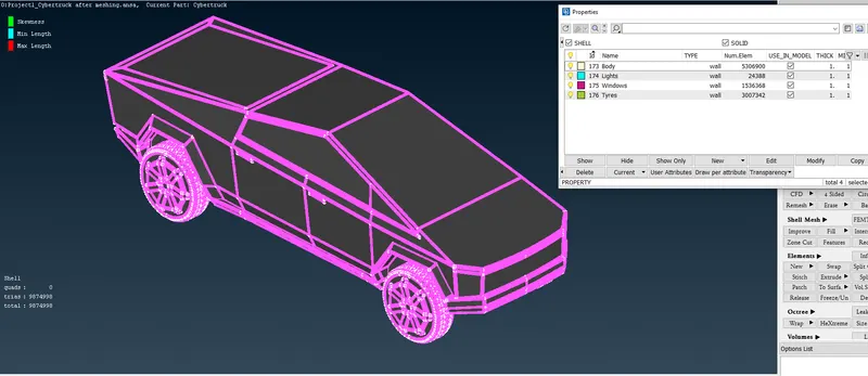
Finally the CFD meshing of the Tesla Cyber Truck is completed.
I am done with meshing now I need to create wind tunnel with given parameters now.
WIND TUNNEL CREATION AND MESHING
The parameters are as follows-
- 4x from front of the Tesla Cyber Truck
- 6x from rear of the Tesla Cyber Truck
- 3x from top of the Tesla Cyber Truck
- Bottom close proximity with tyres
- 1x from the centre plane for left and right sides
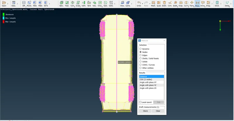
The measured length of the car is 5953. I am considering the length as 6000 for calculation purpose.
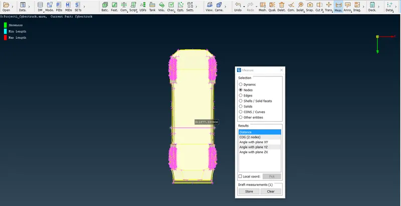
For calculation purpose I am taking the width as 1900
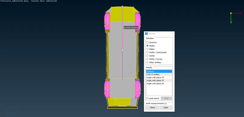
For calculation purpose I am taking the above measured value as 2530.
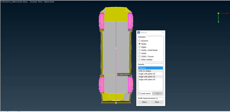
For calculation purpose I am taking the above measured value as 3530.
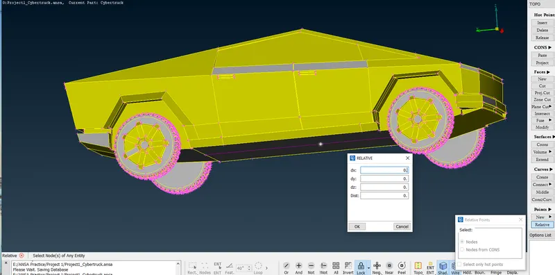
A relative point is created as shown in the above image.
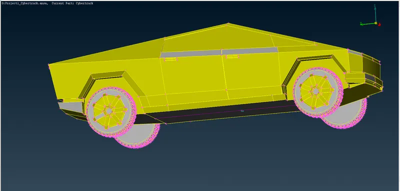
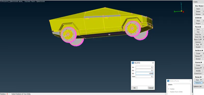
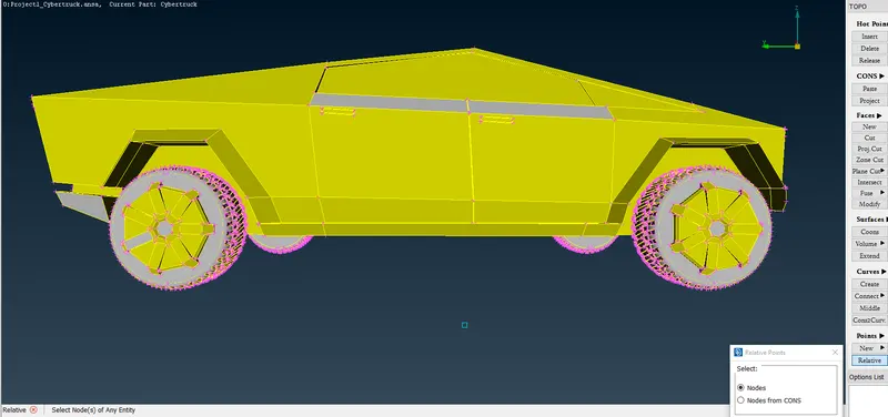
A relative hot point is created as shown in the above image to create a bottom face of the Wind Tunnel.
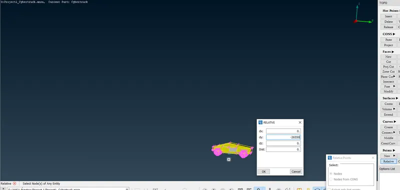
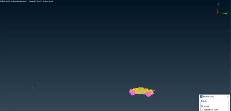
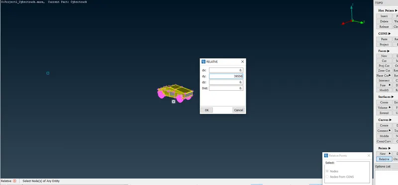
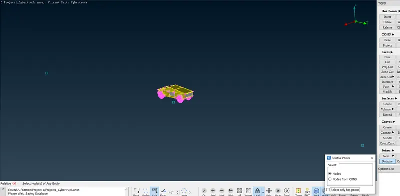
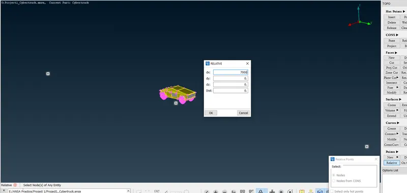
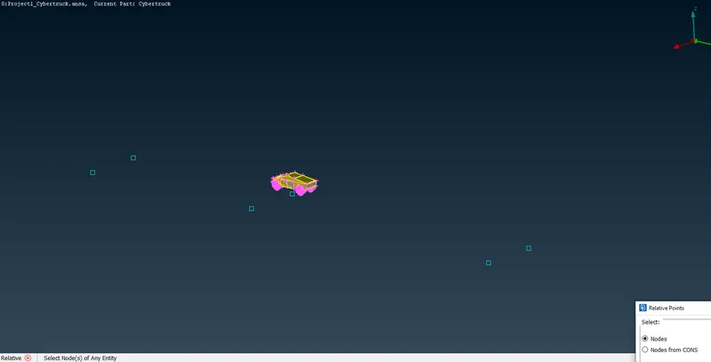
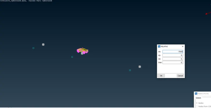
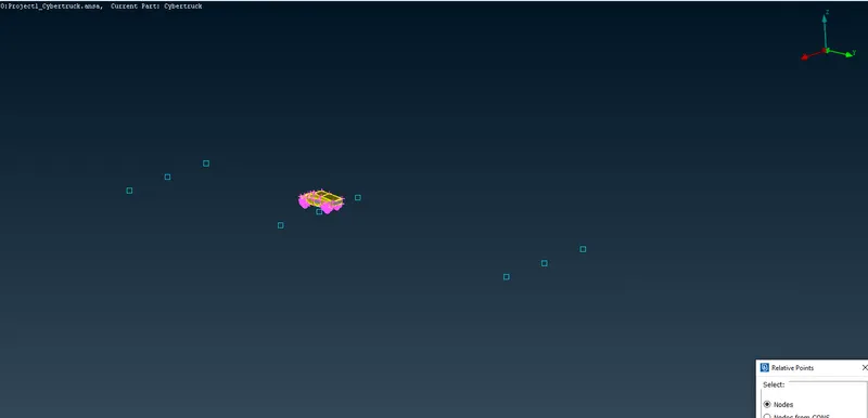
All bottom relative points are created.
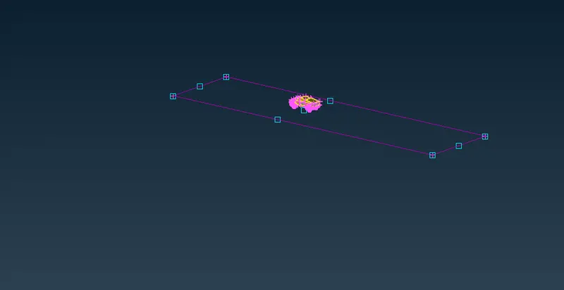
Using create curves and relative points curves are created.
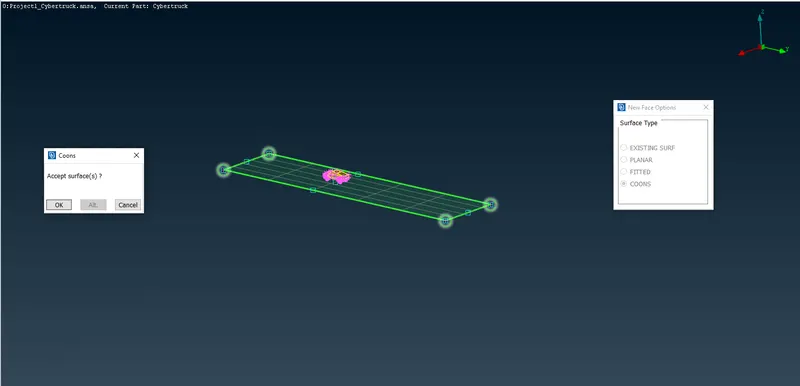
Bottom face of the wind tunnnel is created as shown in the above image.
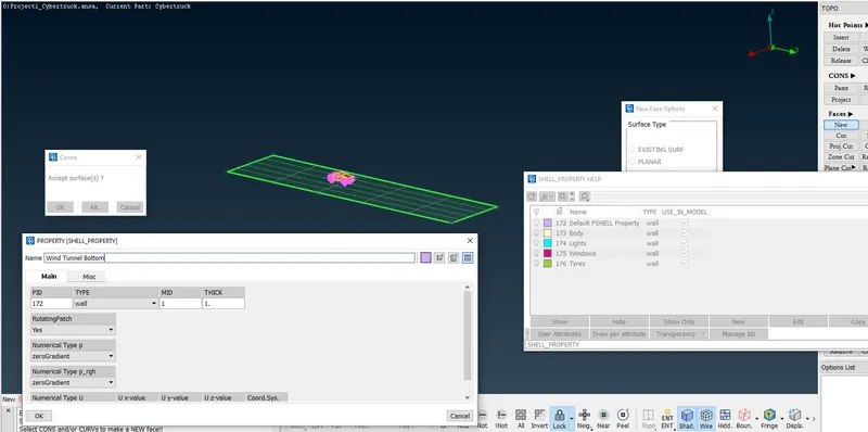
A PID is assigned to bottom face of the wind tunnel named Wind Tunnel Bottom as shown in the above image.
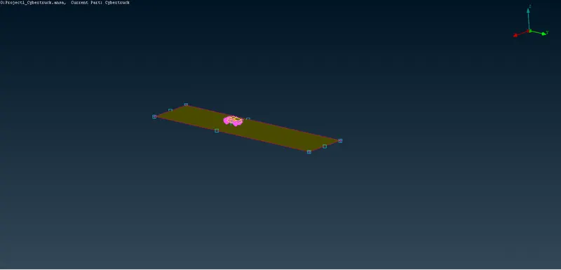
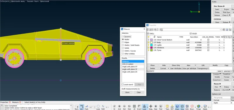
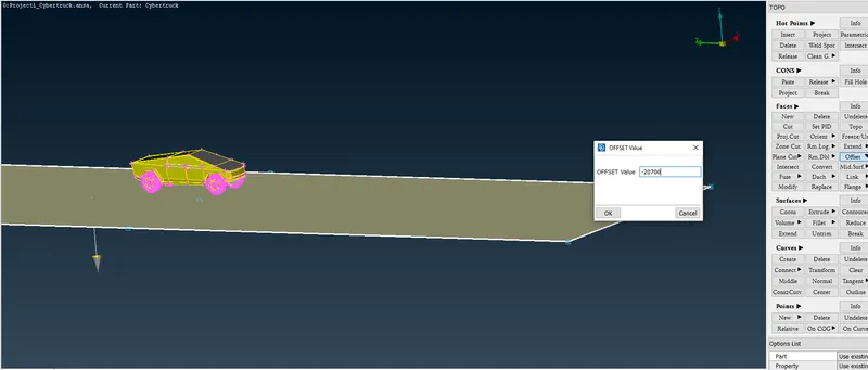
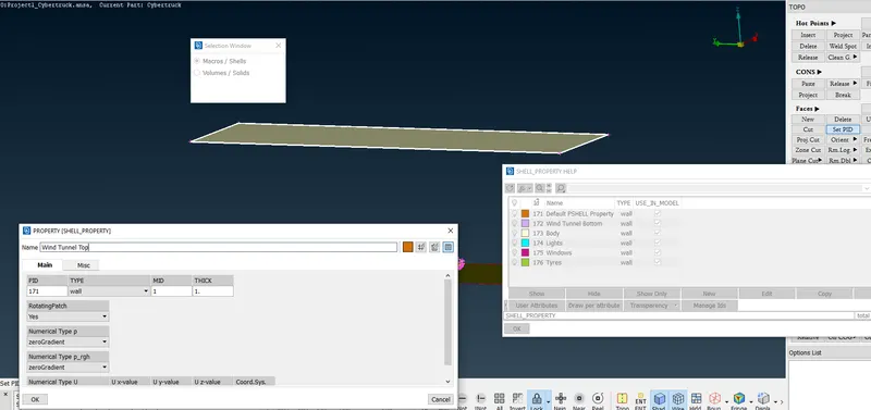
Top surface of the wind tunnel is created and PID is assigned as shown in the above image.
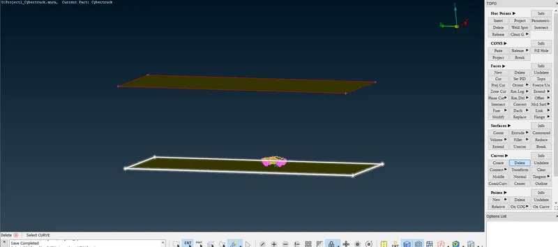
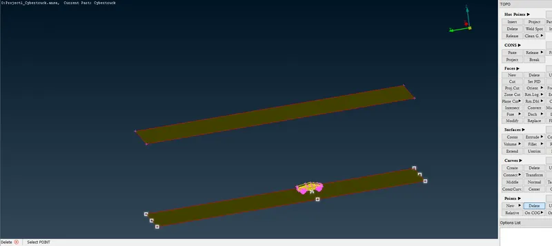
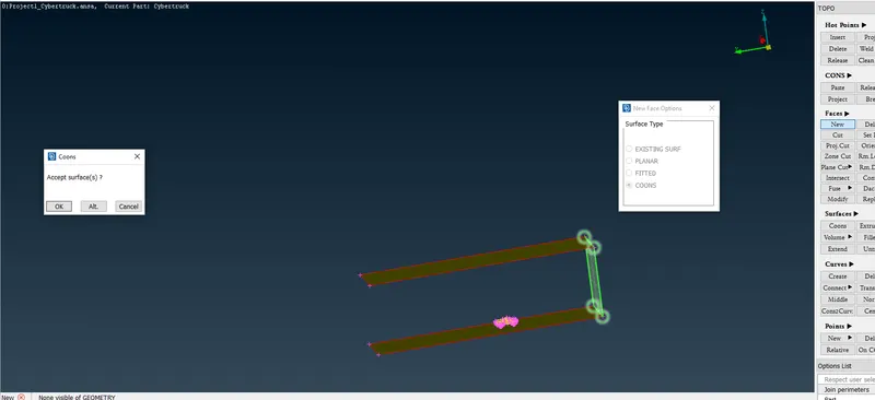
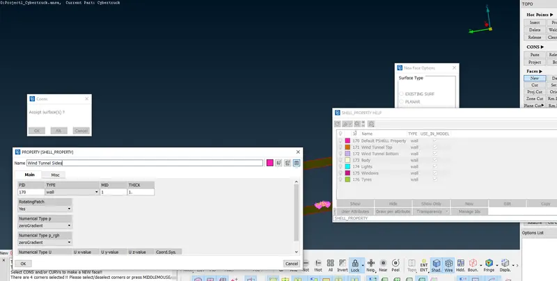
Side surface is created and PID is assigned asshown in the above image.
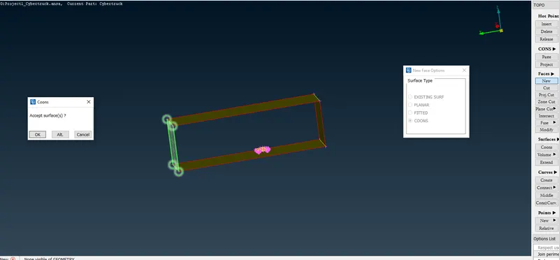
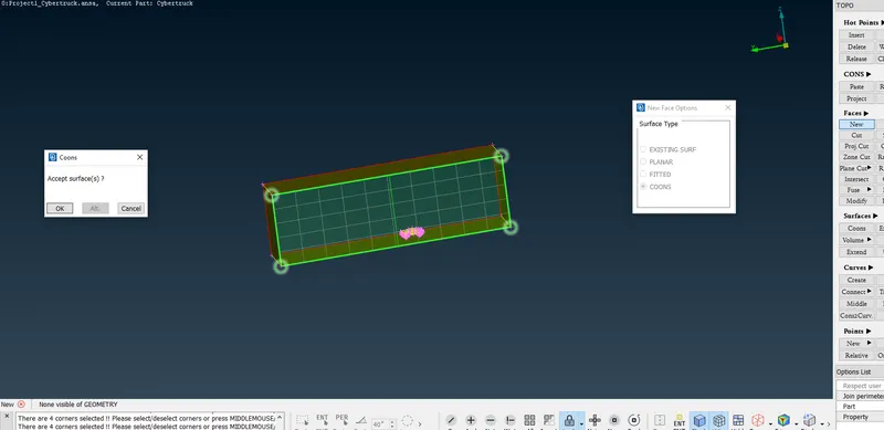
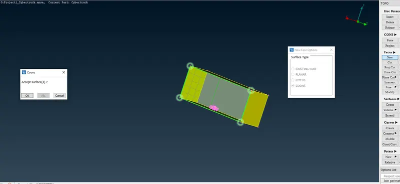
All the side faces of the wind tunnel are created and assigned to PID named Wind Tunnel Sides.
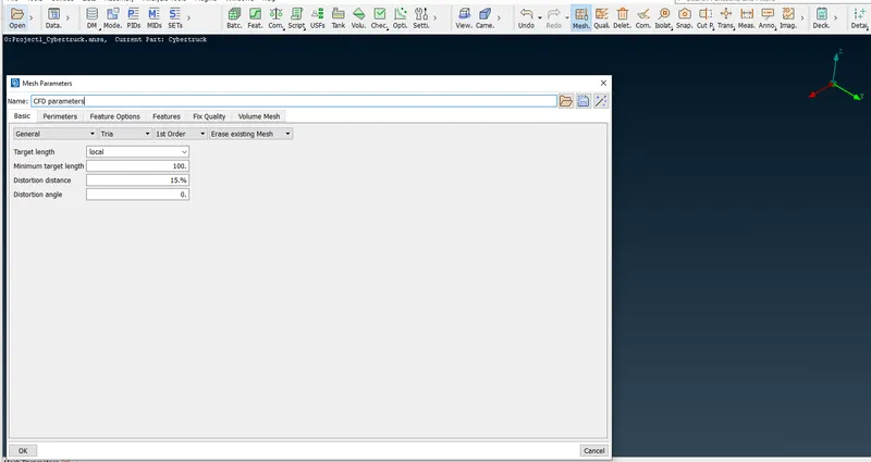
Mesh Parameters are set. Target length for Wind Tunnel Bottom is 100mm.
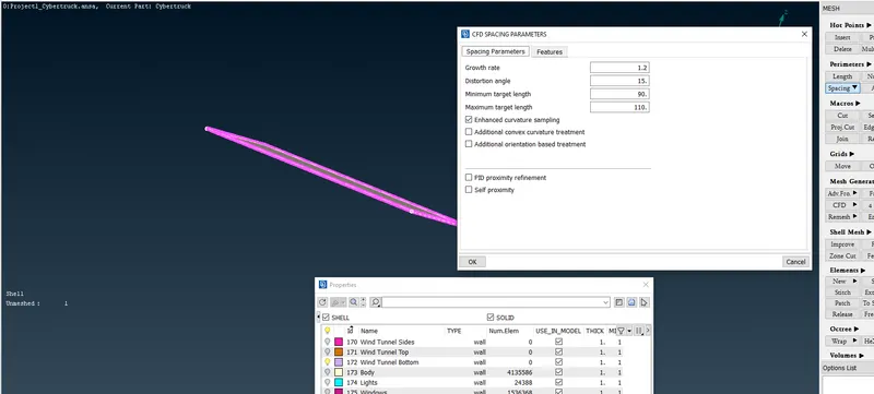
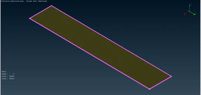
Wind Tunnel Bottom is meshed successfully
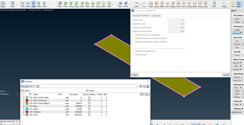
Meshing Of Wind Tunnel Top is attempted.
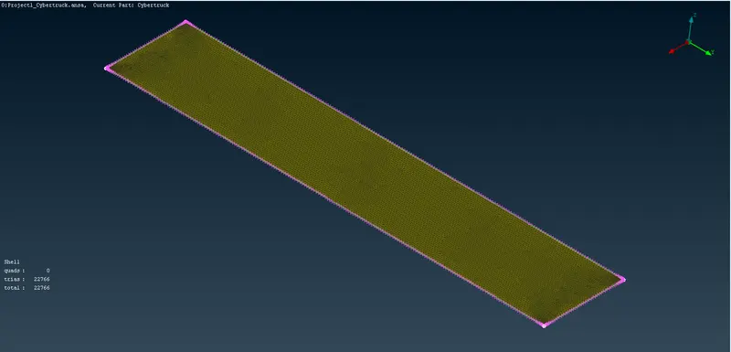
Meshing of Wind Tunnel Top is done successfully.
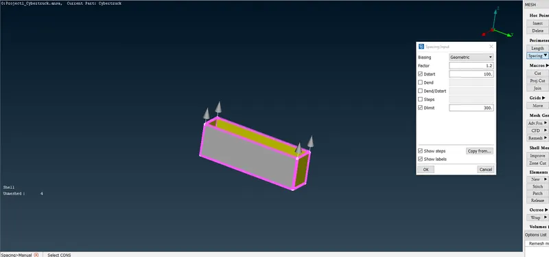
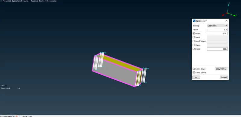
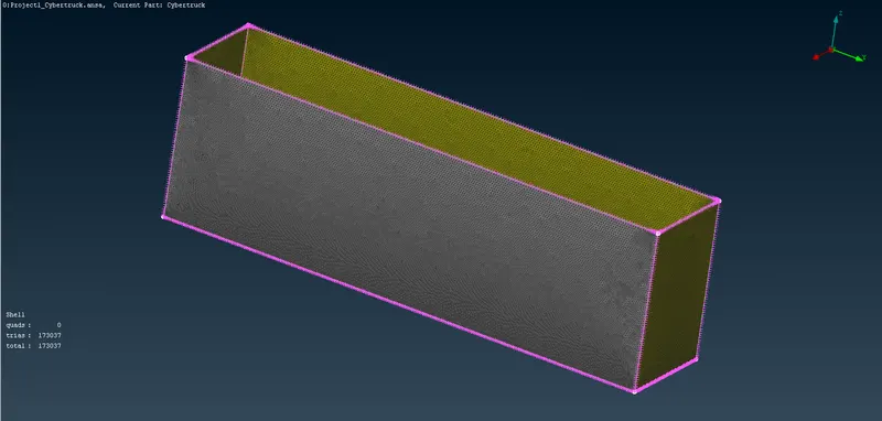
Meshing of Wind Tunnel Sides is done successfully.
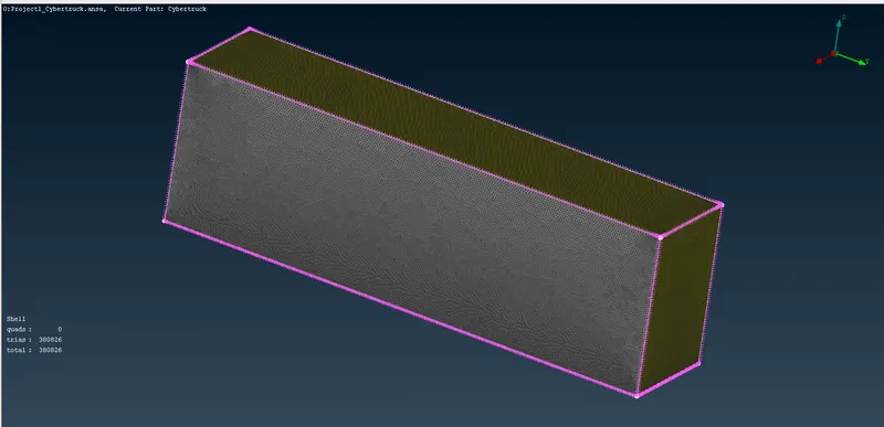
Surface Meshing of the wind tunnel is done.
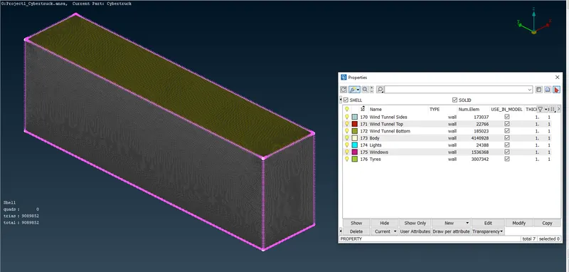
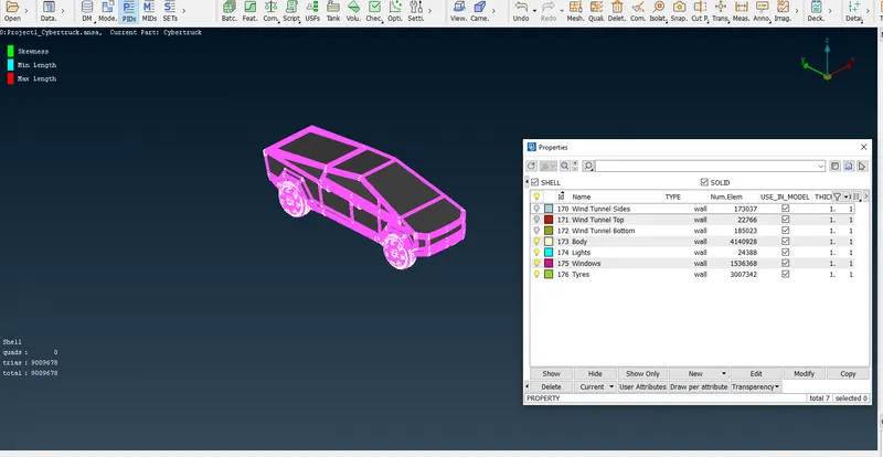
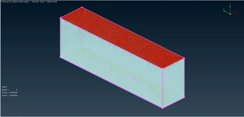
After doing All no off elements or Unmeshed surface were found.
Hence we conclude that CFD Meshing of the Tesla Cyber Truck is done along with Wind Tunnel creation and it's Surface Meshing.
To view Project1_Cybertruck after geometry clean up.ansa file click below link
https://drive.google.com/file/d/1r6svchiflCmWTi0tCWWZfyJaYUg_Jaql/view?usp=sharing
To view Project1_Cybertruck after meshing.ansa file click below link
https://drive.google.com/file/d/15Va9XAWF1qWLlKhm4s3ICEhU2IkSFFtn/view?usp=sharing
To view Project1_Cybertruck after wind tunnel meshing Final.ansa file click below link
https://drive.google.com/file/d/1zrA3huPYOVlsYmbfONP7BK4IUOFqTumH/view?usp=sharing
Conclusion:
- Geometry clean up of Tesla Cyber Truck is done.
- Surface Meshing of Tesla Cyber Truck with Quality Criteria is done.
- Wind Tunnel creation is done.
- Surface Meshing of Wind Tunnel is done.