CFD Meshing for Tesla Cyber Truck using preprocessor ANSA.
Objective :
- To identify & clean up geometrical errors present in the given automotive geometric model.
- To create a surface mesh.
- To Create a wind tunnel around the automotive body.
- To create a volumetric mesh to perform an external CFD simulation for studying the aerodynamical effects of the vehicle body.
Procedure :
- Import the CAD model.
- Identifying & clean up the topological/geometrical errors.
- Geometry close inspection.
- Set up relevant PIDs for assigning different target lengths to different vehicle parts.
- Defining the element size or length.
- Setting the mesh parameters, selecting of meshing algorithm, and generating a surface mesh on the external surface of the model.
- Resolving mesh quality parameters and refining elements according to the given range.
- Creating the wind tunnel for external flow CFD analysis and surface mesh of wind tunnel.
1. CAD Import:
To open a model in ANSA, go to file--> Open--> Browse for the given ANSA file--> Select and click Open. After importing model appears in wireframe mode as shown below.
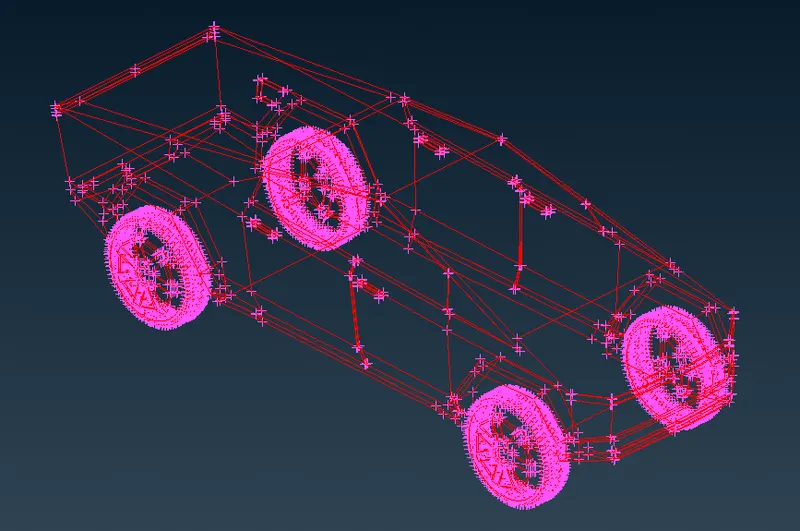
In this geometry, all cons are released, appearing as single/red cons. To join cons and form double cons use the Topo command. Under the Faces option, use the topo command by clicking on the Topo button, selecting geometry, and then confirming using the middle-click button. After this application major red cons were eliminated. The below image shows the geometry after this operation.
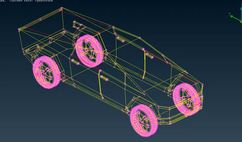
Enable shadow mode to see surfaces. Use the checks manager to identify all red cons and intersections present in geometry.
------------------------------------------------------------------------------------------------------------------------
2. Topology clean-up
Geometry has several topological errors, and missing faces which are indicated by single cons & triple cons, but for the CFD analysis only the double cons should be present. Not even the triple cons are acceptable because they may lead to forming of local volume which will try to form a volume mesh.
It created the whole car inside part as one volume, here tyres are inserted into the body but not attached. Here we can go with two approaches either we can delete the common extra part and perform topo and make the whole car and tyres as one volume or the common part will be deleted and close the holes of tyres such that only the car forms one volume and as tyres are not attached, then each of them forms one volume means 4 tyres 4 volumes. Here the second approach is used. And with these 5 volumes, another volume forms between the car and wind tunnel, which is the volume on which analysis will be performed. So all other volumes would be deleted and the final volume would be kept for doing external flow analysis.
As the only focus is on outside features of the configuration and not on inside features. Requisite modifications were of all the features such that the inside part would form a volume exclusively. Any surface which is causing an intersection error inside would be deleted.
Any small surface should be removed and merged with its neighbour surface and create an absolute surface such that it would not cause a quality error while the mesh generation process. The image shows the red cons present which would be cleared subsequently.
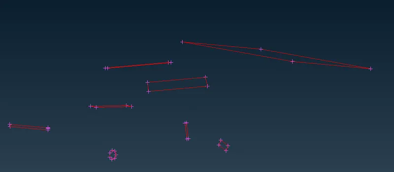
Front left part:
Switch to PID mode for better visuals of red cons
The below image is of the front left part of the body part from outside before topo cleanup.
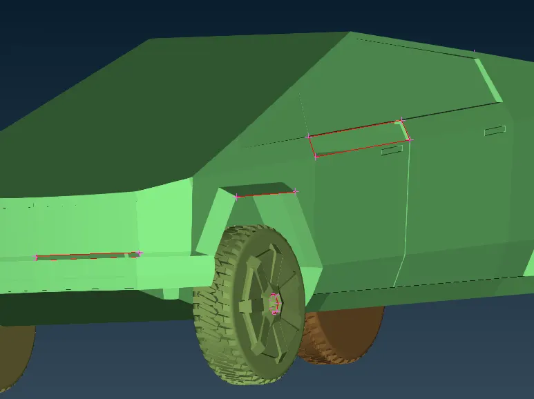
All these red coons were joined using Faces--> New--> Coons option.
Near the window, a pane connecting the window from the body it is joined as a sharp surface which would have created skewness errors in meshing. It is shown below.
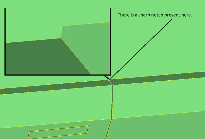
This was rectified using the following procedure:-
| 1. Use the Faces--> Cut option to cut from the top edge present in between windows up to the ending of the edge. | 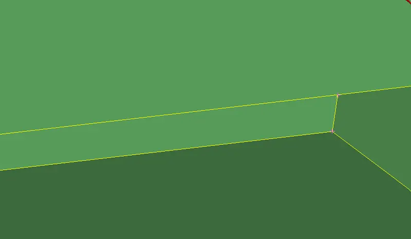 |
| 2. Delete this small surface and bottom adjoining surface using the Faces--> Delete option. | 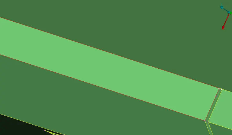 |
|
3. Make a new surface using coons option. |
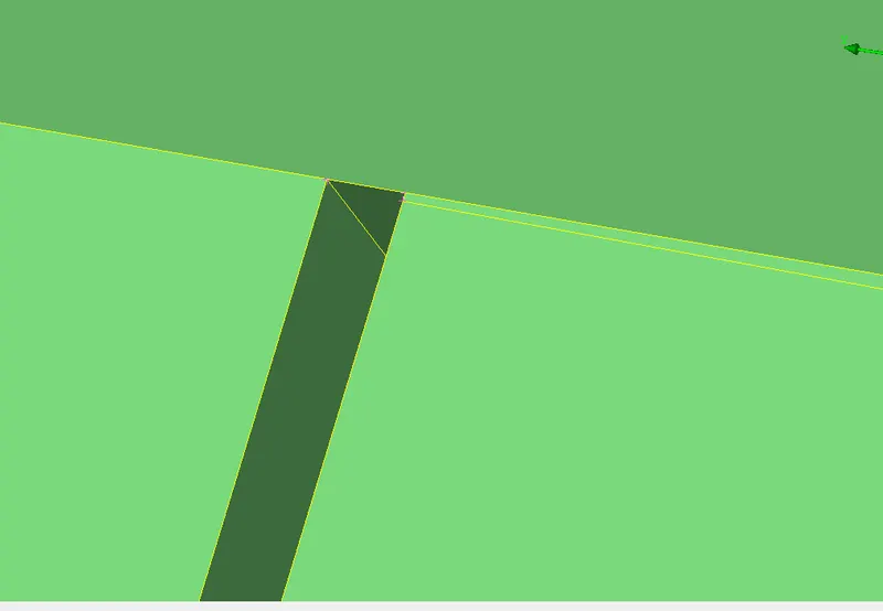 |
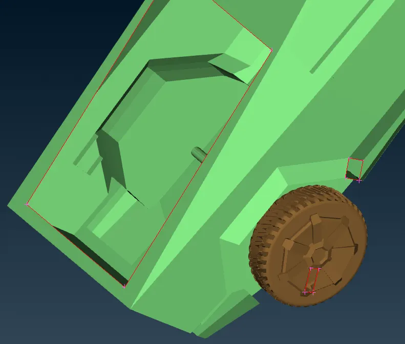
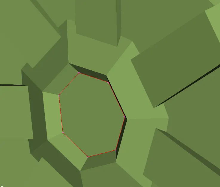
Below shown single cons were easily patched by New--> Coons or fill-hole option.
 |
 |
After clearing all single cons go to the checks manager to check for intersection errors.
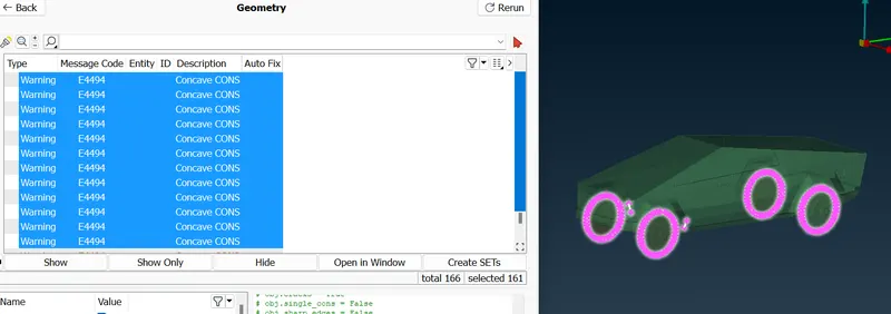
Only convex, concave and a few mixed cons were shown as warnings which could be neglected. Intersections errors were visible between wheel shafts and chassis.
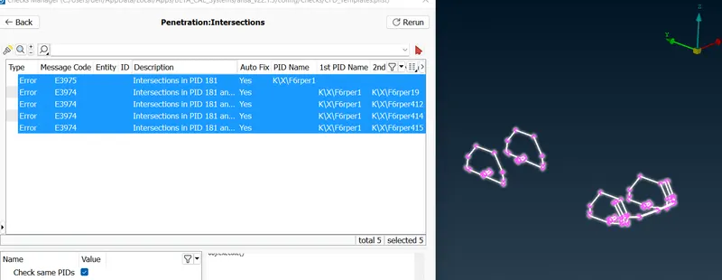
Some intersection errors were present between the front bumper and side skirts of the front side.
Clearing the intersection errors from the front side:
Delete these small intersecting surfaces and then make a face cut as shown below in this image. And then delete that surface.
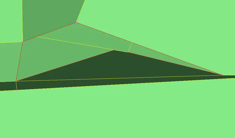
Cut this surface and deleted a small triangle present at the corner.
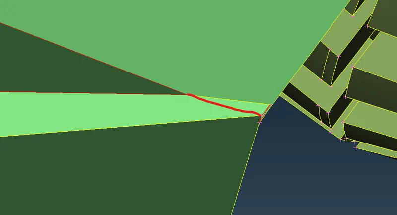
Cut and delete this face as shown below.
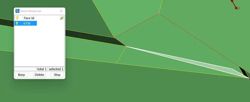
Finally, try to form a new surface and start checks manager. In the checks manager, it displayed 5 intersections, now similarly from the other side intersection errors were removed.
These shafts were deleted with universal delete selection and the surfaces which left were patched using the fill hole option.
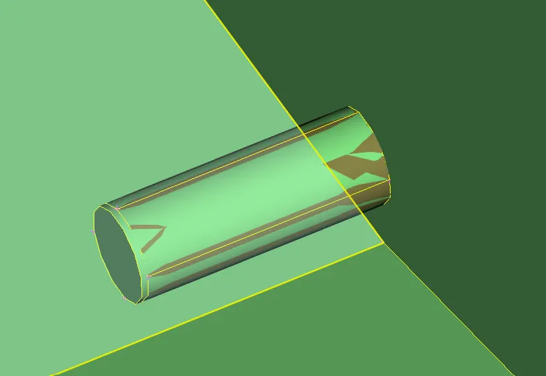
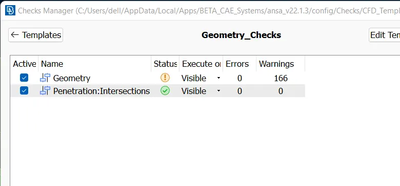
Now again go for the checks manager, 0 intersections and 166 warnings were displayed. All errors had vanished.
But before doing these tasks, we will follow the following steps so that we don't have any off elements later in the meshing stage. Remove small surfaces that were smaller than the minimum mesh length, and directly remove the cut, which was unnecessary if found small. If that cut or feature line is necessary if removed that cut may lose shape. The new cut should also satisfy the minimum length criteria. If not able to cut or that feature line is very important to maintain the shape of geometry, then reduce the min length value so our element length would not fail. By following these steps evaluation of all the PIDs / components was done.
For body PID there were small unnecessary surfaces which were causing off elements in meshing.
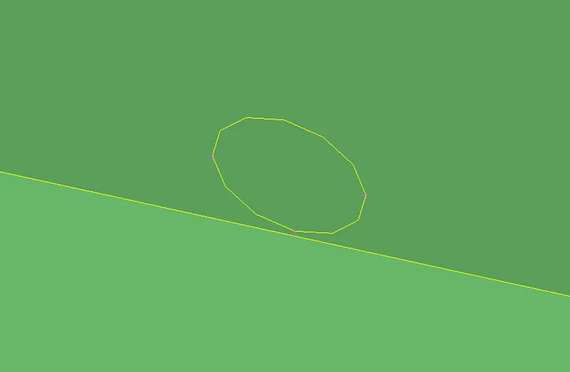
It was found that two extra surfaces which are protruding inside. On the top side, the surface was at two separate lights. It may not form a separate volume but let us clear those extra surfaces and create a new surface over there such that it won't create any minimum length error after meshing. In the below image we can see the extra surfaces.
------------------------------------------------------------------------------------------------------------------------
3. PID Assignment
In this step PIDs were assigned, the PID for different parts and give a name and colour to differentiate between the components and ease up the working on the components individually.This is also done to specify names to different boundary conditions for various parts. We need to activate cross hatches before setting-up PIDs.
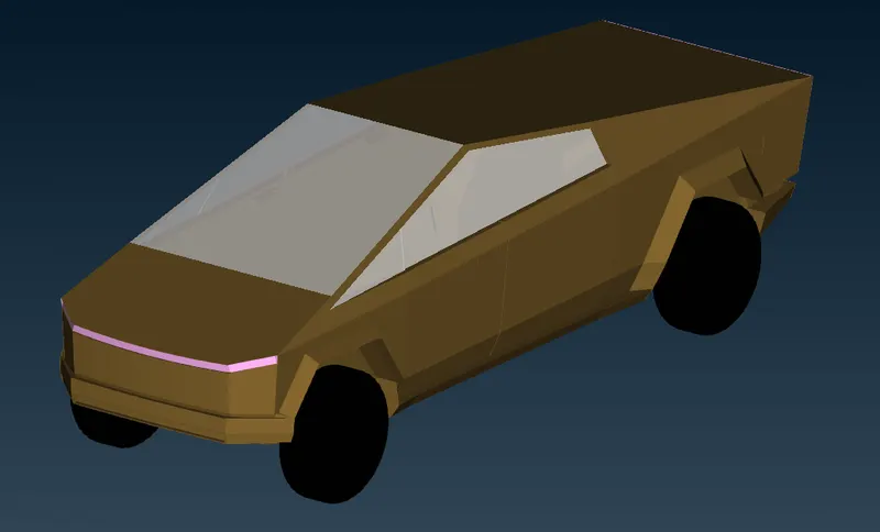
Go in set PID option available is faces flag. Select the faces to be flagged as PID. Press middle mouse button to assign PID. In PID list option. Create new PIDs select and click OK. PID would be assigned to respective surfaces. Given example illustrates PID assignment for body, windows, lights and tyres.
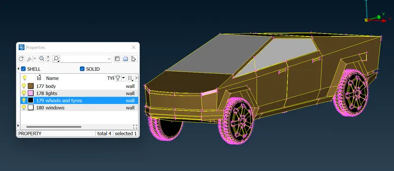
Use compress PID tool for deleting dispensable PIDs.
For aesthetic purpose we also add 20% transperancy for windows to be more realistic in the colour box in PID--> double click PID--> In miscellaneous--> Color--> set transparency as 20--> Click on OK.
------------------------------------------------------------------------------------------------------------------------
4. Meshing
Go for split geometry for saving meshing time application and cpu power. Use Plane Cut option for under faces flag. Before using plane cut add a hop point at top edge and create a hot point at the end edge of body.
Here we perform all the three tasks ,defining the element size or length and setting the mesh parameters, selection of meshing type and generating surface mesh of the CAD model and resolving the errors in the surface mesh by selecting each PID one by one and perform above tasks .
Before meshing we have to give quality criteria .Here we select openFoam solver deck,so that we get the quality criteria of that solver .
Quality criteria was set as 0.5mm skewness with minimum element length as 1mm and maximum element length as 7mm.
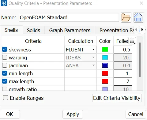
Meshing from largest to smallest component was attempted.
We isolate each component/PID and give above quality criteria(target, min and max length ,skewess etc. ) in quaity criteria and then in mesh parameters . Skewness and give value as 0.5 for all the PID's and also min angle trias as 0.7 . For different parts target length is mentioned in respective table.
| PID | Target Length | Minimum Length | Maximum length |
| 1. Body | 3mm | 2 | 4 |
| 2. Windows | 2mm | 1 | 3 |
| 3. Lights | 4mm | 3 | 5 |
| 4. Tyres | 2mm | 1 | 3 |
If selected the perimeters attached to other PID , it may lead to erase of mesh at that location .
Here if value of length was not given by selecting the required perimeters and mesh directly by giving 3 mm in the mesh parameters ,then whole model will be meshed with 1mm as element length, as 1mm at the start for resolution .So it is necessary to give length in perimeters .
Length is assigned by making all PID's visible, this is done to select properly the required perimeters such that the mesh of other PID's is not erased .
All the visible errors of minimum length and maximum length can be overcome by reconstruct and then remaining errors can be corrected by a combination of mesh improvement tools .
------------------------------------------------------------------------------------------------------------------------
BODY
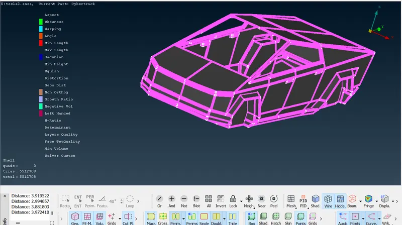
CFD mesh algorithm was used on body. Perimeters and macros for body were assigned as 3mm. For clearing OFF elements reshape, reconstruct algorithms were utilised. For clearing some remaining off-elements manual MOVE option was used for adjustment of elements using node control points. Minimum target edge length allowed was given as 2mm and maximum target length as 4mm.
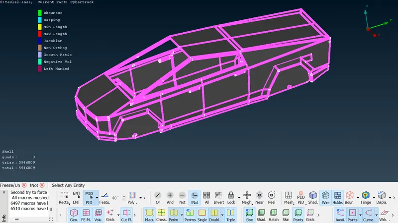
Total number of elements is body were 5946009
------------------------------------------------------------------------------------------------------------------------
WINDOWS
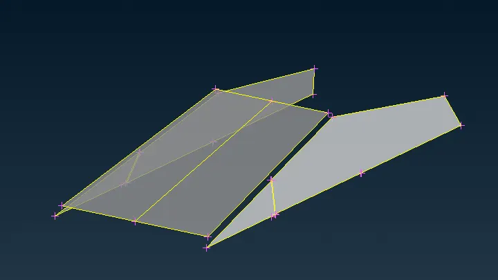
Window was isolated using !NOT option. Target length for windows is given as 2mm. In Mesh Parameters, Minimum target edge length allowed was assigned as 1mm and maximum target length as 3mm.
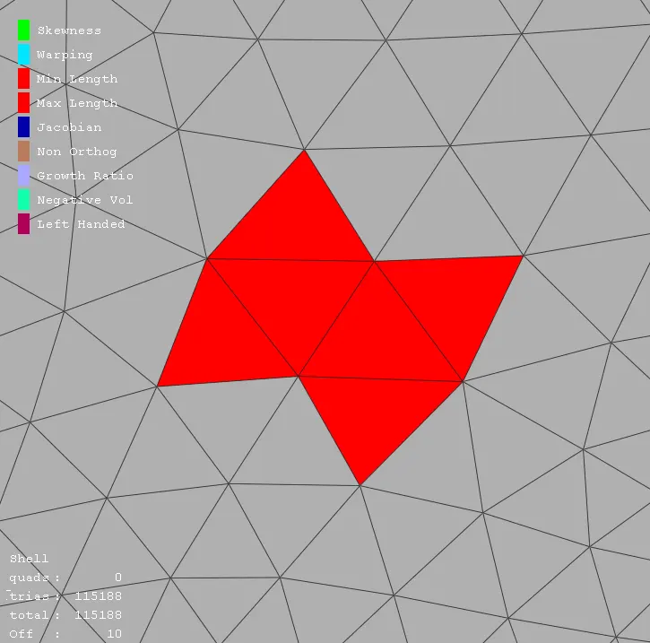
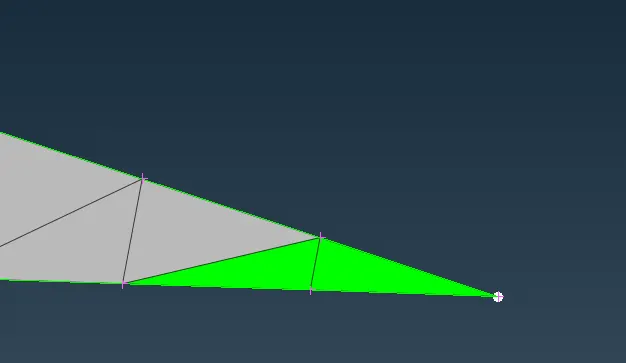
These off elements were repaired using Move, Reshape and reconstruct tools.
 |
 |
After reconstructing off elements mesh was completed with ~2mm elements. 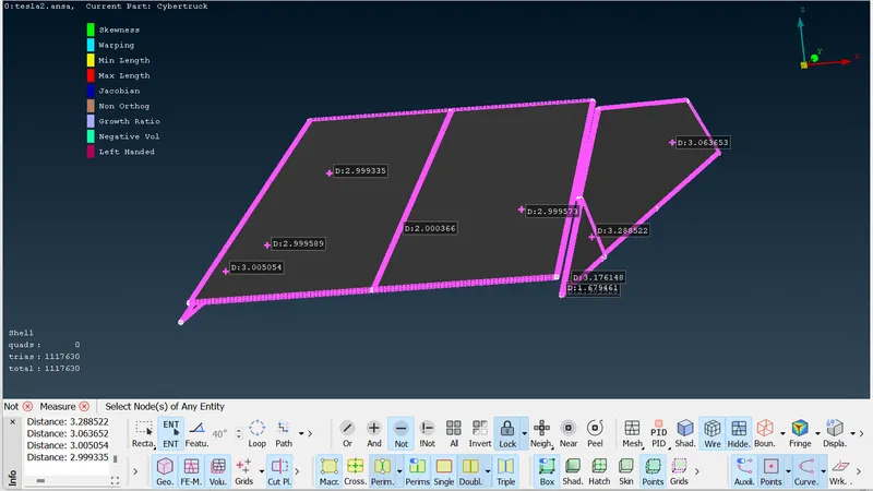
Total number of elements in windows were 1117630
------------------------------------------------------------------------------------------------------------------------
TYRES
With windows tyres were also meshed because both were having same target length that is 2mm.
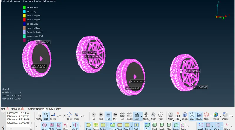
Total number of elements in tyres were 4501738.
------------------------------------------------------------------------------------------------------------------------
LIGHTS
Target length as 3mm same operations were performed as above. Target length was 4mm and min=3 max=5.
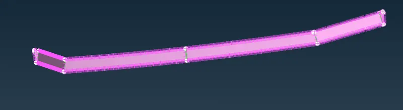
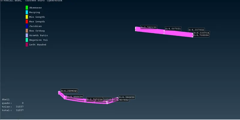
Total number of elements in light were 31037.
Finally check for any remaining off elements if present. Remove them using reshape and move. Unfreeze elements and apply meshing on parts which were remained unmeshed using Free algorithm.
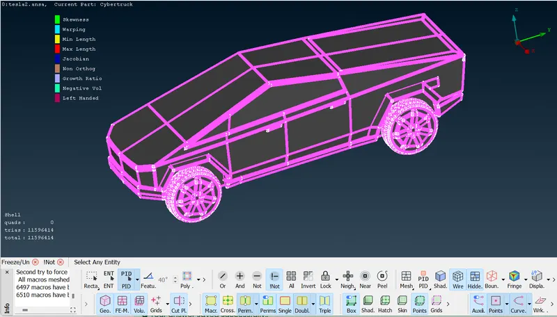
Meshing is completed with 0 off elements and total elements of 11596414. (~1.16 crore elements).
------------------------------------------------------------------------------------------------------------------------
Wind Tunnel :
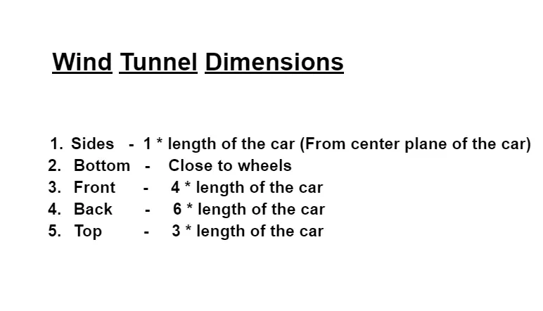
To perform external flow CFD analysis a wind tunnel has to be created around the car. It is created in TOPO mode as a Rectangular box. The Dimensions of the wind tunnel is also important so as to capture the exact flow around car. The dimensions are as follows:
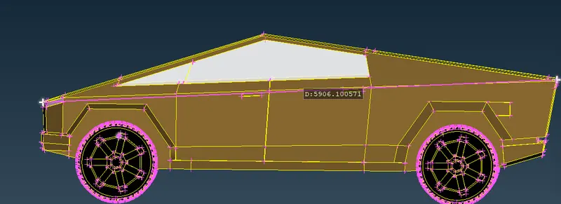
In order to create a Wind tunnel, first create points by selecting relative at 650mm from body to bottom by selecting a hot points of middle central length at a distance of 650 mm to bottom as shown.

Vehicle length can be taken as ~5910.
By taking that point as reference , we create anotheer point to front of car at a distance of 4* 5910 = 23640mm ( 5910 mm is length of car).
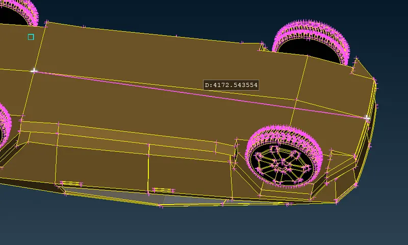
Relative to this point vehicle forward length is taken as 4180 which is also addel in forward point now the expression becomes.
`=4x+4180=23640+4180=27820`. Using relative point option forward point is created.
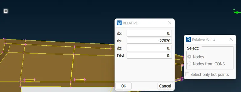
Similarly backward point was also created.
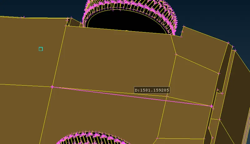
Backface length`=6x+1582=35460+1582=37042`
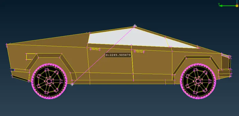
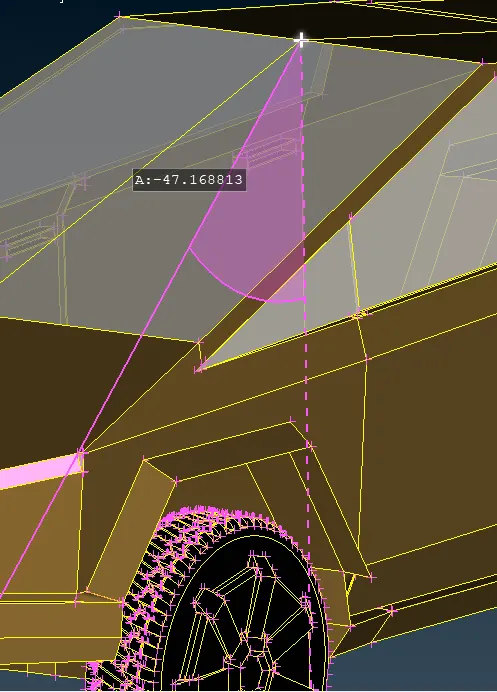
Vehicle height can be calculated by given dimensions as `L*cos(theta)=2250*cos48=1505.543`.
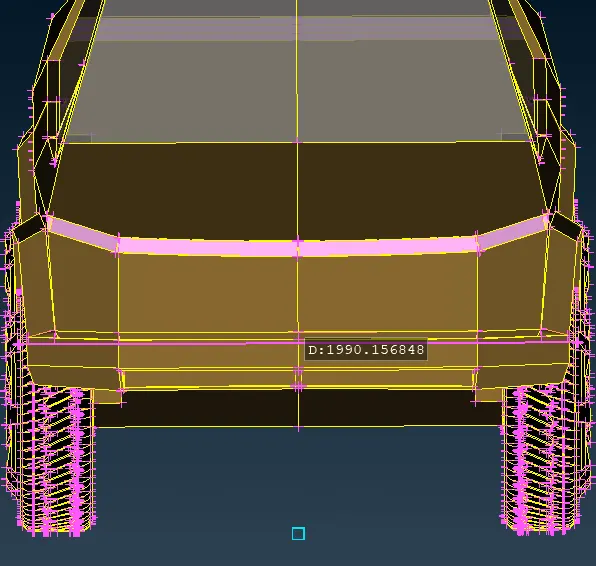
Side to Side length of vehicle can be considered as 1990. Offset these points for vehicle length and adding half of the side length 995. Use relative option to offset these points in both left hand and right hand side.
Offset point length=`5910+995=6905`
Use these points and create curves so that surface can be made. Use New--> Coons option to create a new face under faces option. Assign PID named bottom for new face.
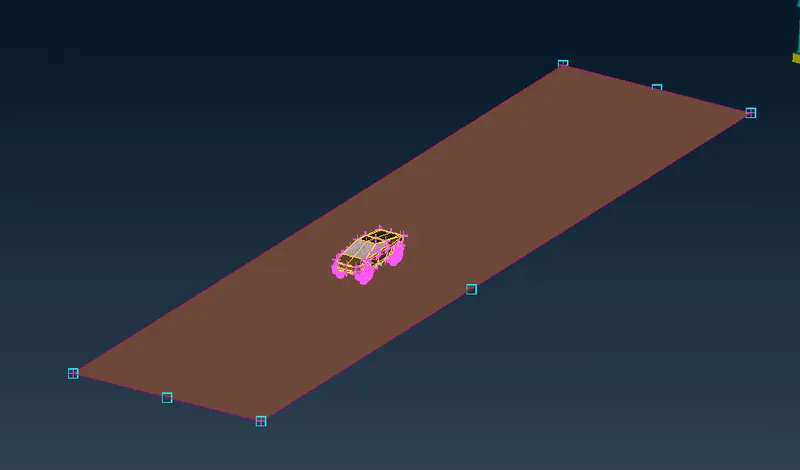
Delete these points and curves as their work is completed.
Height of vehicle is given as: `2250cos48^@=1505.5`
Add this height, height of base of vehicle from bottom of wind tunnel and desired wind tunnel height from top of truck i.e 3 times length of the truck.
| Measuring car length from base to Top point. ~2250. | Measuring tilt angle of length with vertical for accurate measurement. Angle=~`48^@`. |
 |
 |
Expression for offset copy dimension calculation with respect to bottom plane for top plane: `3x+1505.5+650=17730+1505.5+650=20535.5`
Use transform--> copy option for making top plane. Top plane is created and assigned PID name as 'top'.
Created other surfaces i.e inlet, outlet and side-walls of wind-tunnel and proceeded for wind tunnel meshing.
Windtunnel is completed and visible as shown below:
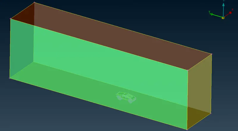
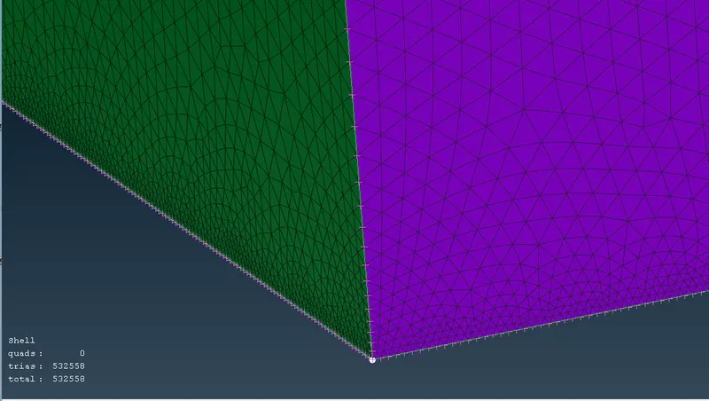
From side walls mesh would grow in vertical direction and get coarsened with increasing height of tunnel. This is done due to the fact that near the walls of object we want to capture aerodynamic effets and variables, so mesh should be refined below to increase accuracy of results and coarsened above to reduce computational time.
This can be done by using the spacing (manual) option under perimeters in mesh utility menu.
Hide the vehicle geometry and start meshing on windtunnel.Geometry biasing option is used & set the dmin value as 30 and dimit value as 120 and factor as 1.1 and select all the four vertical perimeters. Arrow should pointt at the growing direction of mesh, here upwards. Target length for CFD mesh would be given as 25mm to 125mm.
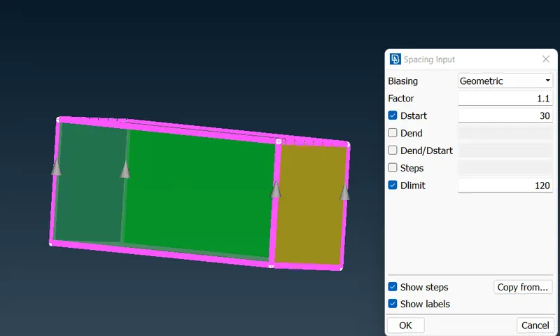
But before that we surface the top part by giving a length of 120 mm and bottom part with a length of 30 mm .Then generate surface mesh.
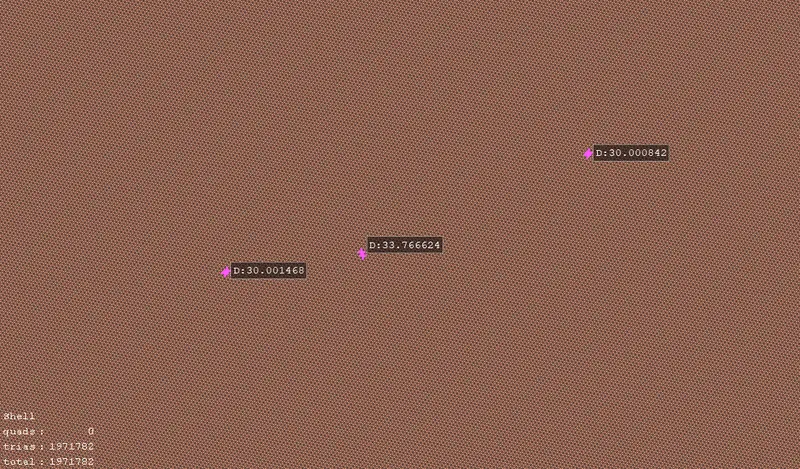
Maximum target length for bottom face is kept as 35mm and minimum target length as 25mm
Surface mesh for bottom face.
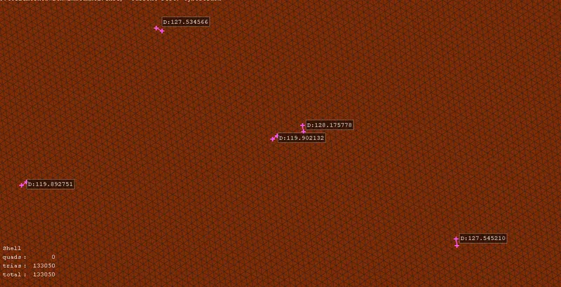
For top face maximum target length was given as 130 and minimum target length was assigned as 115mm.
Surface mesh for top face.
In the below image we can see that the mesh length is varying and increasing from bottom to top .
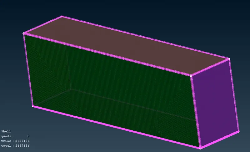
Total 3637186 elements were involved in surface meshing of wind-tunnel.
------------------------------------------------------------------------------------------------------------------------
ANSA File link: https://drive.google.com/file/d/1lbg2VICzqExdSC-9MixohWTuAcn8YOcO/view?usp=sharing
Learning outcome:
In this process of working on this project we have learned how to,
- Cleanup of the topological errors .
- Geometry check-up and setting-up PID's and defining the element size or length.
- Setting the mesh parameters and quality criteria, selection of meshing type and generating surface mesh of the CAD model .
- Quality criteria tool and quality parameters.
- Resolving the errors such as skewness, min & max lengths using various tools.
- Set-up Wind Tunnel as per given dimensions for external flow CFD analysis and surface mesh of wind tunnel.
Conclusion :
- The imported CAD model of Tesla cyber truck was Topologically Cleaned & Corrected.
- Surface mesh was generated with the required element size.
- Reconstructed the mesh as per the mesh quality required at sharp edges, small surfaces, Corners & at Intersection of edges.
- Errors occured were rectified in the Mesh by using Move.
- Created a wind tunnel for external aerodynamic analysis.