Project 1_Analyze and design a steel building to 10T CRANE as per IS standard code using TEKLA STRUCTURAL DESIGNER.
Aim - To calculate the 10T crane loading based on the inputs
Model the structure according to givel drawings and apply loads
Procedure
Given data
Crane capacity is 100KN
Self weight of crane - 160KN
Weight of crab - 35KN
Approx min approach of the crane hook to gantry girder - 1m
C/C dist b/w gantry rails - 20m
c/c dist b/w coloumn - 6m
Wt of the crab - 35KN
Yield stress of steel - 250N/n2
Wheel base is 3m
Calculation
Max wheel load
Max concentrated load on crane - 100+35 = 135KN
Self weight of crane will act as UDL 160/20 = 2.86
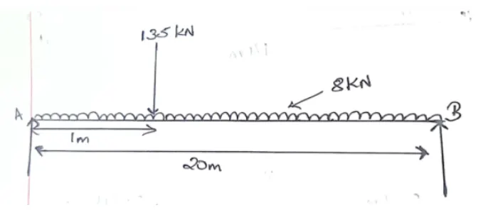
Taking moment about B
Ra x 20-135 x 19-8 x 20 x 10
Ra = 208.25Kn
Rb x 20 -135 x 1-8x20x10
Rb = 86.75KN
Ra + Rb = 295 Kn
The reaction from the crane girder is distributed equally on two wheels at the end of the crane girder
Max wheel load on each wheel of crane = 208.25/2 = 104.125KN
Max BM
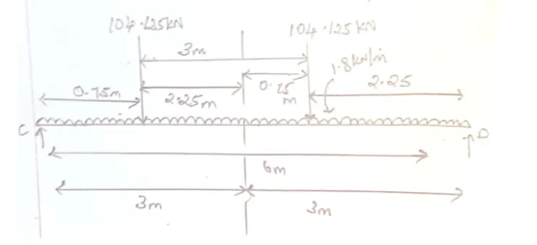
Assume self weight of gantry girder as 1.5m
Total dead load = (self wt of rail + self wt of gantry girder)
300+1500 = 1800N/m
1.8Kn/m
Taking momentum about about D
Rc x 6 - 104.125 x (2.25+3) - 104.125x2.25
Rc = 130.15KN
Rd x 6-104.125(0.75+3)-104.125x0.75
Rd = 78.09 KN
BM under wheel due to live load = Rd x 2
78.09 x 2
= 156.18KN
BM due to impact = 0.10 x 156.18 (10% increase)
15.618 KNm
Total BM due to live load and impact load =
= 171.79KNm
BM due to dead load = Wl2/2 = 1.8x 6x6/8 = 8.1
Max BM
=171.79+8.1 = 179.89Kn/m
Max SF
For max SF one of the wheels should be at the support
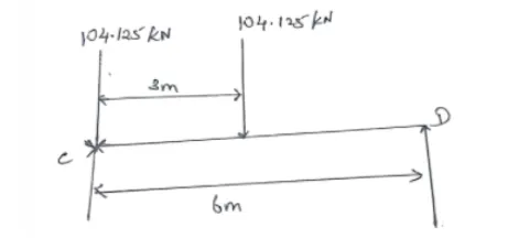
Rc x6-104.125x6-104.125x3
=156.18 KN
The max SF due to wheel load is 156.18 KN
Lateral forces
Lateral force transverse to rails = 5% of the wt of crab & wt lifted
0.05 x 135
= 6.75KN
Lateral force on each wheell F1 = 3.375 KN
Max horizontal reaction due to the lateral force by proportion at C
lateral force x reaction at c due to vertical load / max wheel load due to vertical load
3.375x130.15/104.125
=4.21KN
At D
3.375x78.09/104.125
=2.53KN
4.21+2.53 = 6.74KN
BM due to lateral load by proportion = 3.375x15.18/104.125 = 5.06KNm
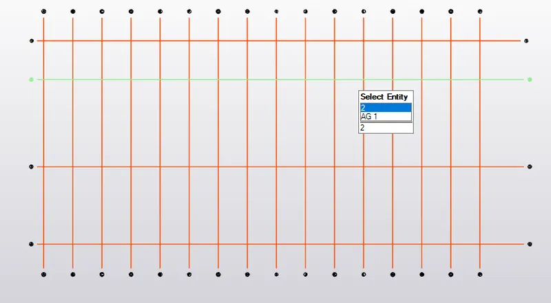
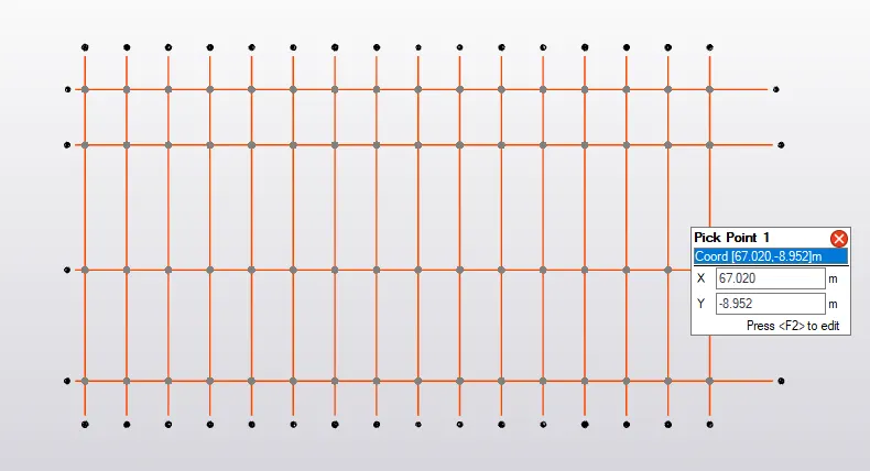
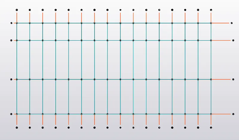
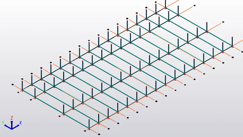
 -
-
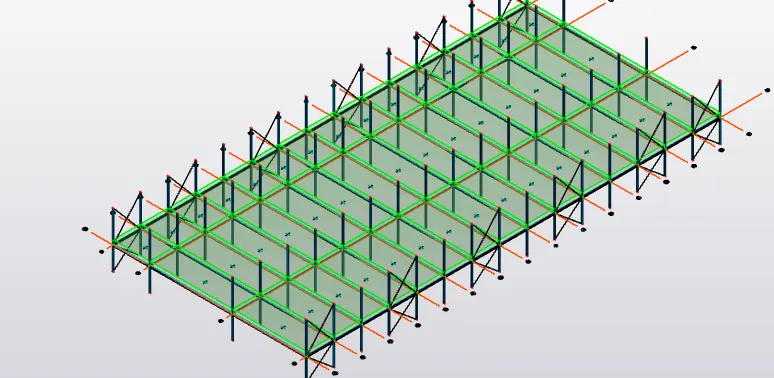
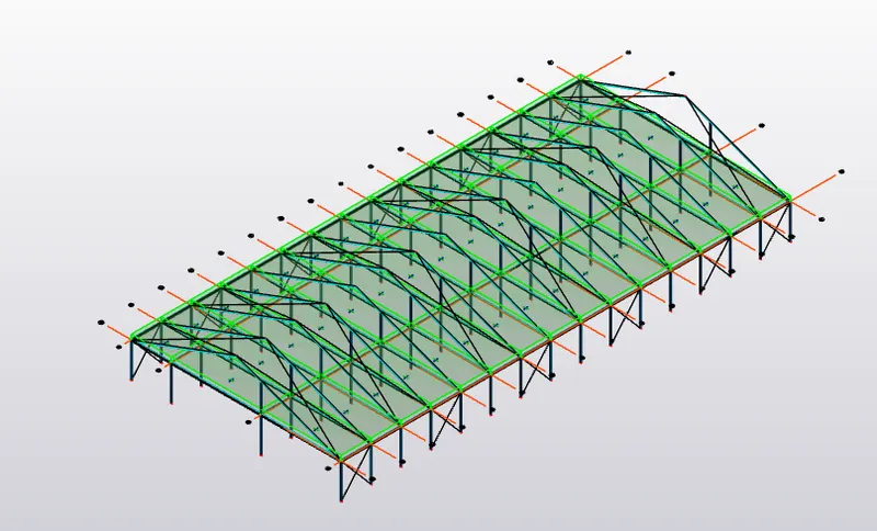
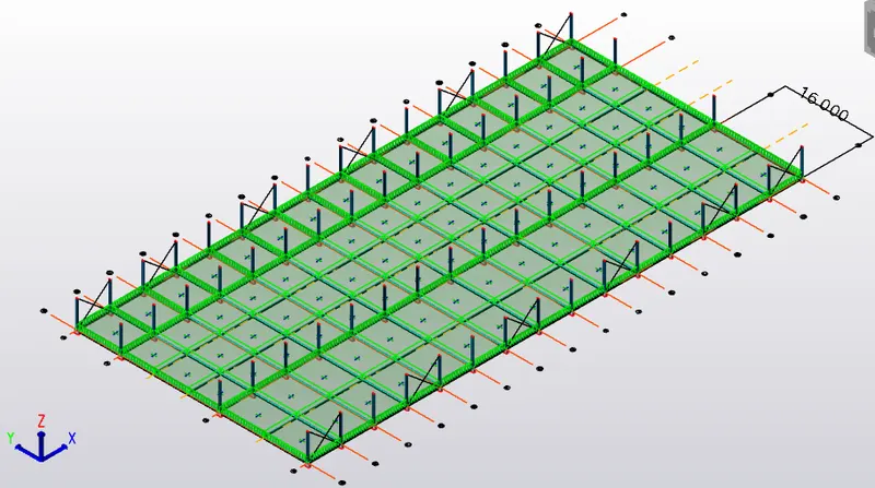
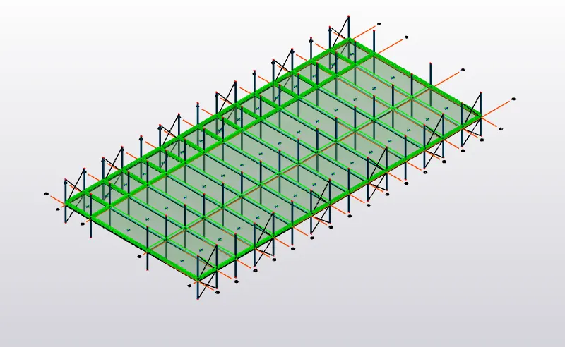
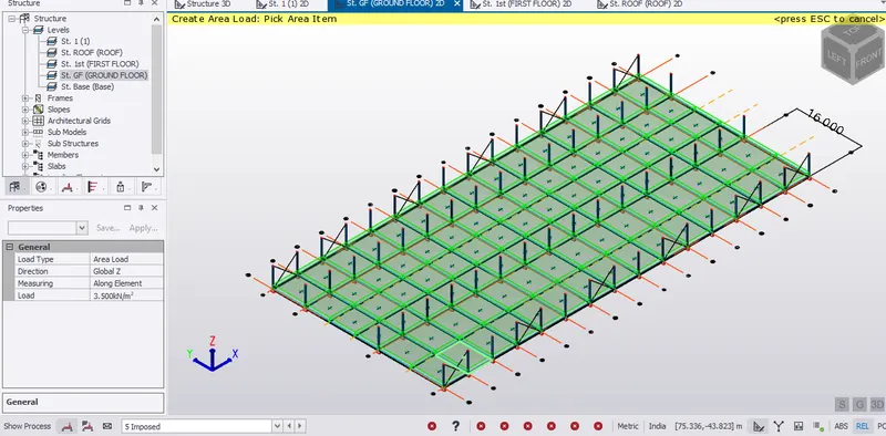
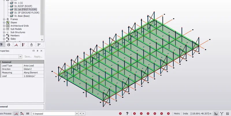
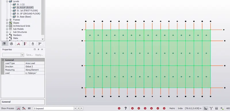
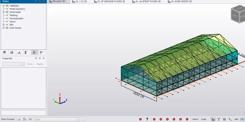
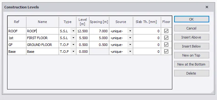
Levels
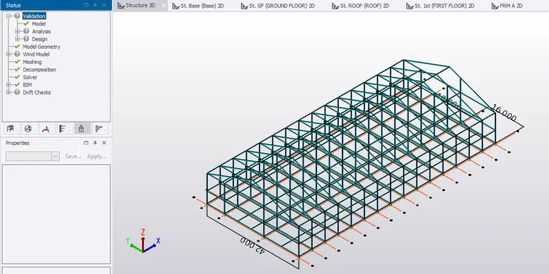
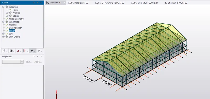
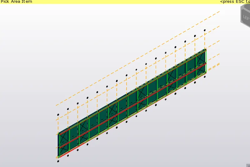
In the models there is construction lines invoke that command
Then add levels one by one
Base as foundation at 500mm from base
Then first floor at height of 5
Second at height of 7
Then roof at spacing of 6
Grids
In the same tab there is grids tool
Then draw first grid line
Then select parallel grid line and give distance by clicking F2
Do same to all the grids
The give perpendicular distance
Then give parallel to all the grids
Pedastrals coloumns
manage property sets then new then concrete coloumns
Give size of 400x800
Then model in the grids
Give base as base and top as GF
Then steel coloumns
Manage property sets and then steel coloumns
Give properties as UB 356 and you can change it later if not satisfied
Add in the model whereever required
Base as GF and top as roof
Beams
Primary and secondary beams
Nwe and steel coloumn give properties as UB838x292x226
Add in the model in all the floors
Rafter
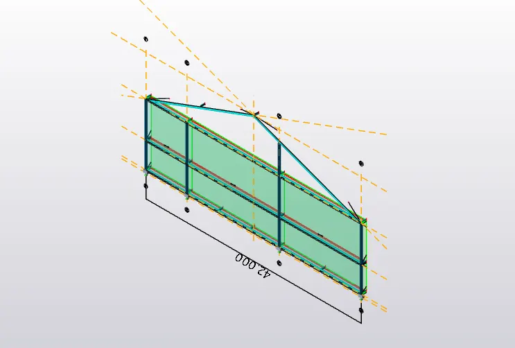
In the same way give rafter
Add new dteel beamm and name it as rafter
Give properties as the coloumn properties
Give in on of the frame and copy to all the coloumns
In the same way connecting beams are added
Noe bracings
Add new property as stell brace
Give property as 150x150x10 as equal angle
Add in all the floors and roof at the ends and in the intermediate whereever you feel is required
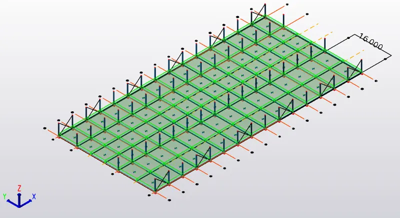
Slabs
Add new property as general slabs and
Give as slab on the beams
Then give thickness of 250 or 300 and OK
Model in all the floors as per the drawings
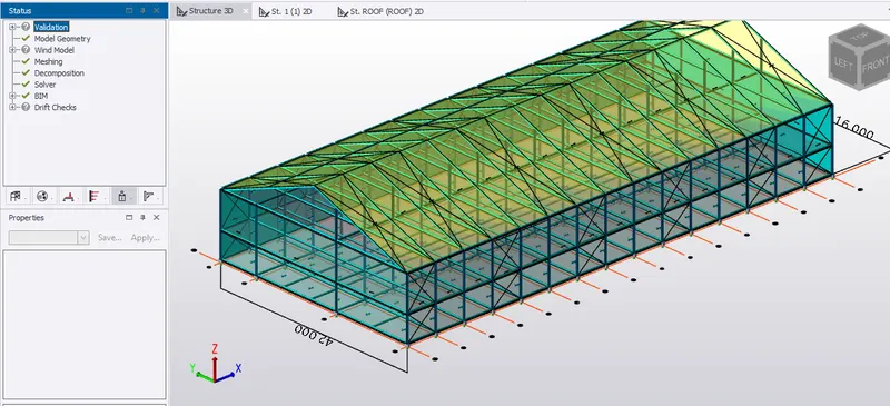
Then add the roof panel
Also add the wall panell
Dead loads
Finishers as given 0.05m
0.05m x 24Kn/m2(density)
=1.2Kn/m
Brick wall load
Wall thickness 1540mm
For ground floor height is 5.5m
20x0.150x5
= 15.5
For first floor
height is 6.8m
Then load is = 21.7Kn/m
Slab load is calculated by the software
Ceiling is 0.3Kn/m
Then loads
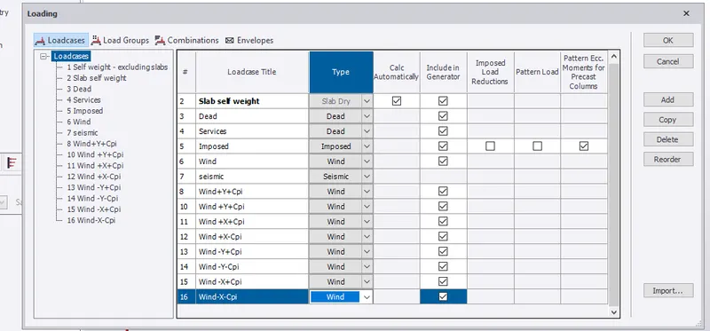
In the load cases in the loads tab
See weather all the loads are there are not if not add new as wind and type as wind
Seismic as seismic type
Then go to load combo
Generate new load combo
Table then see all the load combos and next and finish
If you want to add new combo add new
Dead loads are already calculated
Self weight is calculated by software itself
Finishers loads
1.2 KN/m2
Select dead in the bottom left bar
Then add area load give value as 1.2
Select all the slabs it will add the loads
Check in 3d
Do in all the floors
Wall loads
Ground floor
15.5 KN/m2
Select dead in the bottom left bar
Then add line load give value as 16.5
Select all the beams it will add the loads
Check in 3d
First floor
21.5 KN/m2
Select dead in the bottom left bar
Then add line load give value as 20.4
Select all the beams it will add the loads
Check in 3d
Roof loads
Switch on roof panel
Area load and give load as 1.5
Start applying on teh roof
Validate in every interval and rectify errors
Wind load calculation
Basic wind speed - 39 m/s
Terrian category - 2
Max spacing - 7.2m
L (x) dist = 90
W (y) = 38
H = 12
Ratio of wall to roof
Wall (l/w) = 1
(h/w) = 2.36
Roof (h/w) = 0.31
Refer the values to table 5 (IS 875 P-3)
We will get Cpe values on the faces
Face A = 0.7
B = 0.25 ( away from structure)
C = 0.6 Away
D = 0.6 Away
Risk coefficient (K1) = 1 (Table 1 , 39 wind speed)
Wind speed variation with height (K2) = 1 (Table 2 up to height 10m)
Topography factor (K3) = 1 (C 5.3.3)
K4 = 1 (C-5.3.4)
Design wind pressure (Pz) = Vb+K1+K2+K3+K4
Pz = 39m/s
Design wind pressure Pz = 0.6 x Vz2 = 0.91Kn/m2
Roof angle = 27 degrees
Internal pressure coefficient Cpi = 0.50
-Cpi = -0.50 (C- 6.2.3.2 0-90)
Face A
+Cpi -Cpi
Cpi 0.7 0.7
Cpe 0.7 0.7
Cp 0.2 1.2 (Cp = Cpe-Cpi)
Pz 0 1.4
Total wall pressure 0 1.4
Factored pressure 0 1.75 (pressurex1.05)
Face B
+Cpi -Cpi
Cpi 0.7 -0.7
Cpe 0.25 0.25
Cp -0.75 -0.75 (Cp = Cpe-Cpi)
Pz 1.2 1.2
Total wall pressure 1.25 1.25
Factored pressure 1.325 0.125 (pressurex1.05)
Because External pressure is same on face C and D so do both sare same pressures
Face C & D
+Cpi -Cpi
Cpi 0.5 -0.5
Cpe 0.6 0.6
Cp 0.1 1.1 (Cp = Cpe-Cpi)
Pz 1.2 1.2
Total wall pressure 1.25 1.25
Factored pressure 1.625 0.125 (pressurex1.05)
For ROOF EF
Y direction
Cpe = -0.12,0.4 for 27 degrees of roof and do interpolation
+Cpi -Cpi
Cpi 0.7 -0.7
Cpe -0.4 -0.4
Cp -1.1 0.3 (Cp = Cpe-Cpi)
Pz 1.2 1.2
Total wall pressure 1.25 1.25
Factored pressure -1.375 0.375 (pressurex1.05)
For ROOF GH
Y direction
+Cpi -Cpi
Cpi 0.7 -0.7
Cpe -0.4 -0.4
Cp -1.1 0.3 (Cp = Cpe-Cpi)
Pz 1.2 1.2
Total wall pressure 1.25 1.25
Factored pressure -1.375 0.375 (pressurex1.05)
Apply on all the faces as we done by changing the load cases
Apply wond loads on the model
First create load cases
Give wind type for all the loads
+Y+Cpi
+Y-Cpi
+X-Cpi
+X+Cpi
-Y+Cpi
-Y-Cpi
-X+Cpi
-X-Cpi
Select wind load case from the bar
Wind +Y+Cpi
Select he frame
On the side A
On the load tab select area
Give global Y direction
Give load as 0.24 and select all the panels on side A
Check weather loads applied on not in 3D
Select wind load case from the bar
Wind +Y+Cpi
Select he frame
On the side B
On the load tab select area
Give global Y direction
Give load as -0.950 and select all the panels on side A
Check weather loads applied on not in 3D
Select wind load case from the bar
Wind +Y+Cpi
Select he frame
On the side C&D
On the load tab select area
Give global X direction
Give load as -1.4 and select all the panels on side C&D
Check weather loads applied on not in 3D
Select wind load case from the bar
Wind +Y-Cpi
Select he frame
On the side A
On the load tab select area
Give global Y direction
Give load as 1.625 and select all the panels on side A
Check weather loads applied on not in 3D
Select wind load case from the bar
Wind +Y-Cpi
Select he frame
On the side B
On the load tab select area
Give global Y direction
Give load as 0.125 and select all the panels on side B
Check weather loads applied on not in 3D
Select wind load case from the bar
Wind +Y-Cpi
Select he frame
On the side C&D
On the load tab select area
Give global X direction
Give load as -0.325 and select all the panels on side C&D
Check weather loads applied on not in 3D
For load case
-Y+Cpi and -Y-Cpi
Inter change the faces any apply the same loads
A as B and B as A
C as D and D as C
Add load for the roof now as Global Z
Y direction
Select load case as +Y+Cpi of FH
Give area load of -0.77 on one side
Then selecct y-Cpi
Then give areal load of -1.14 on other side
Then -Y+Cpi and -Y+Cpi and interchange the sides on the roofs
Then in X direction
Select +X load case of X+Cpi
Give load of 1.25 and 0.625 on the either sides
Then X-Cpi
Give area load of 1.325 snd 0.325 on teh oppsite either side
The load case of -X+Cpi and -X-Cpi interchange the directions
Chek all the loads in the 3D
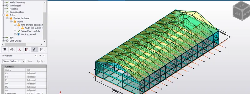
Analyse the project
The analysis will be done
Open frames
Check the maximum moment and shear force
Then select that frame
See all the parameters pass or not in our structur the coloumn is failed in buckling combined
Then change the coloumn
Add new coloumn ifrom the universal coloumn as 356
Then re run the analysis
The coloumn is safe
In the same way check all the frmes
Whereever the coloumn fails add new one and make it safe
Beam analysis
Take a beam has maximum moment and check the member
Our beam failed in deflection
Increase the size of the member and if still fails
Then in the properties
Make top flange as continuesly restrained as YES because on the top there is slab
Moment major is also failed
So increase the modulus
Check the modulus Ze and give more than that
Then also the member is failed
Then change the beam as Universal beams in the members
Then the beam is passed
Do same for all the beams
Or copy and properties ti all the beams in the review tab
Make all the beams as fixed on both ends