Project 1_Analyze and design a steel building to 10T CRANE as per IS standard code using TEKLA STRUCTURAL DESIGNER.
Ans:
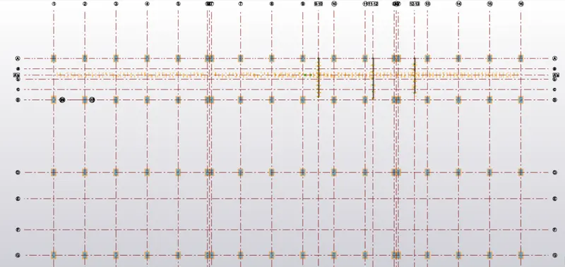
Layout plan of our model is hereunder as follows:
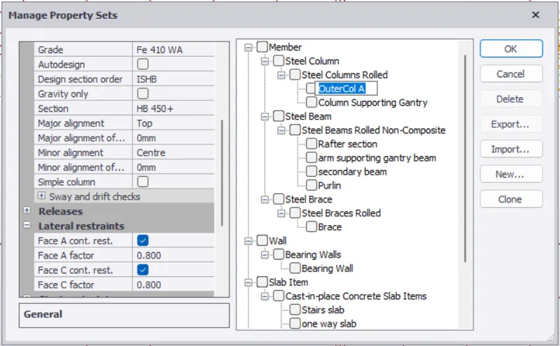
Outer Columns on Top & Bottam (Grid "A & G")
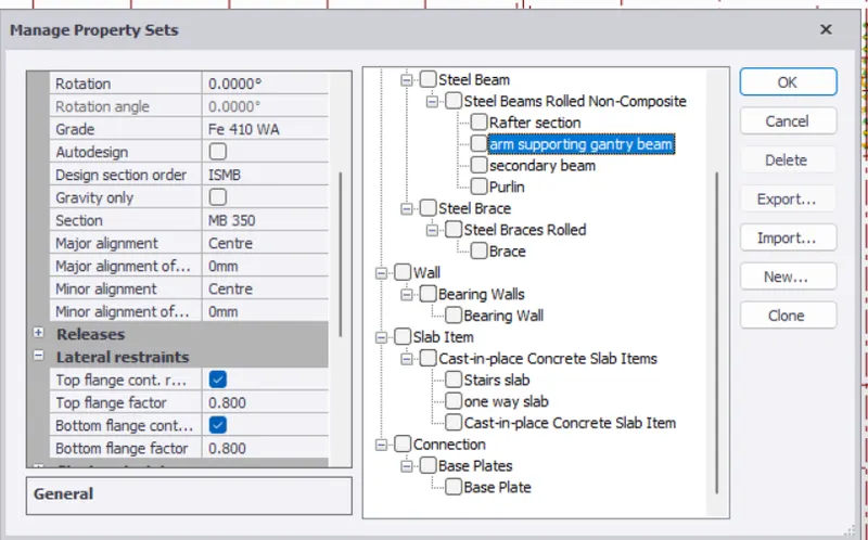
have properties enclosed here under as follows:
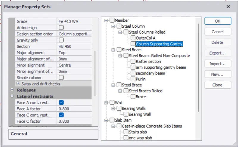
While Centered Columns in the above layout plan have the properties mentioned as follows:
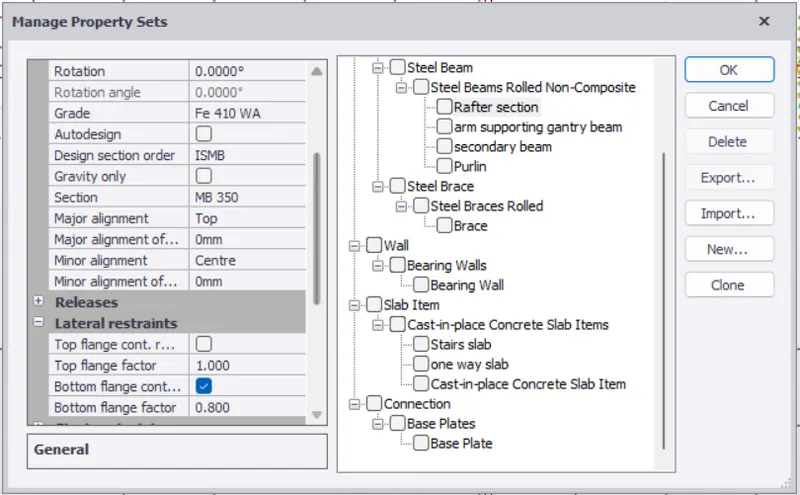
Steel Beam named as "Rafter Section" have the properties mentioned as follows:
Arm Supporting Gantry Girder (1m Cantilever Beam projecting from the centered column at a height of 8.5m from the base as shown below )
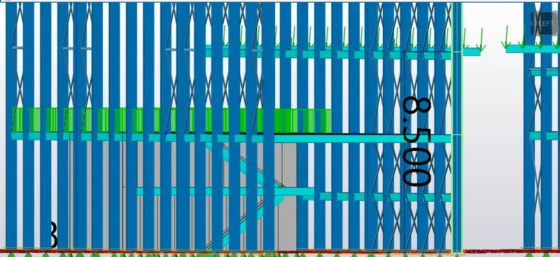
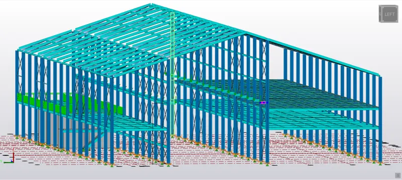
Highlighted member in above screenshot represent "Arm Supporting Gantry Girder"
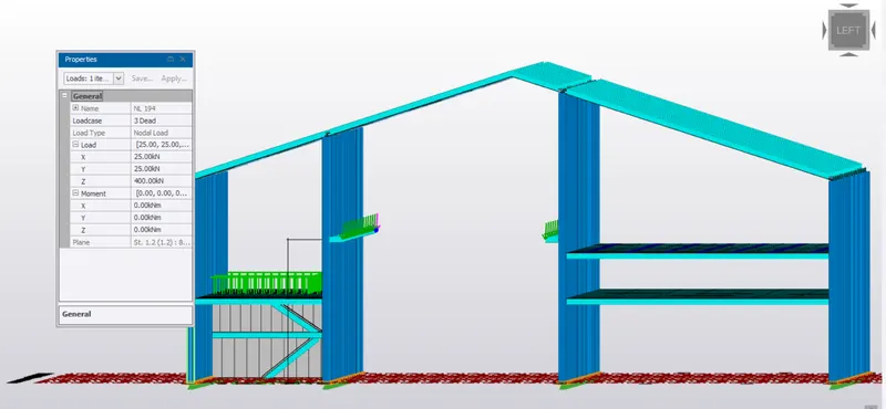
Nodal Load acting on 1 m Cantilever end (fx, fy, fz)=( 25, 25, 400) KN.
(main Load is applied here is mentioned above).
Due to above mentioned condition, deflection dia. of various frame for the serviceability criteria is attached here under as follows:
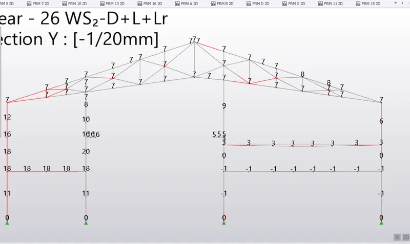
Frame 2 deflection diagram due to serviceability criteria: DL+LL+Lr
=====================================================================
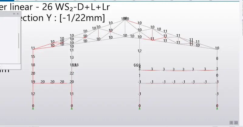
Frame 4 Deflection Dia.
======================================================================
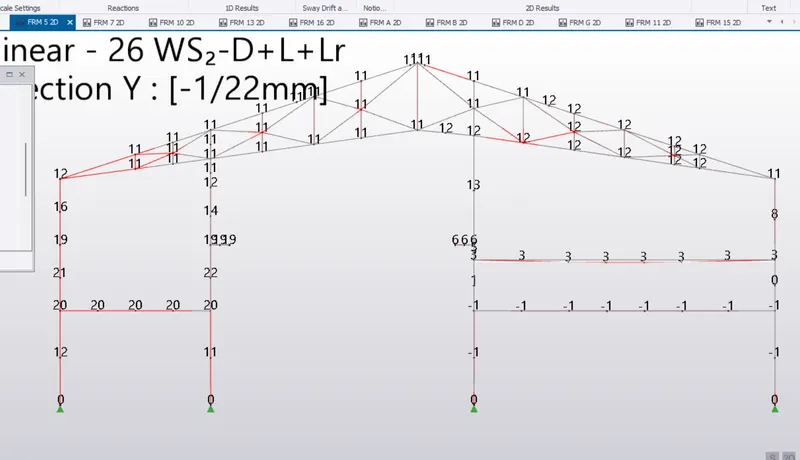
+Frame 5 Deflection Diagram
================================================================
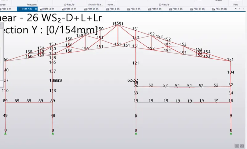
Frame 7 Deflection Dia.
===========================================================================
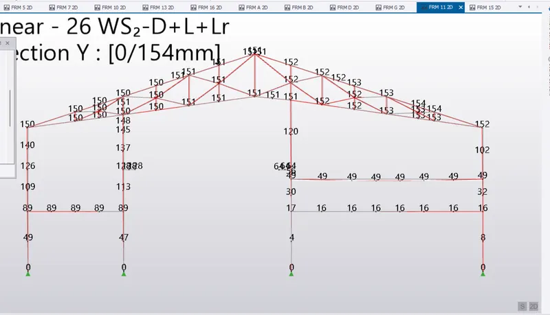
Frame 11 Deflection Dia
===============================================================
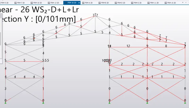
Frame 16 Deflection Dia.
==============================================================================
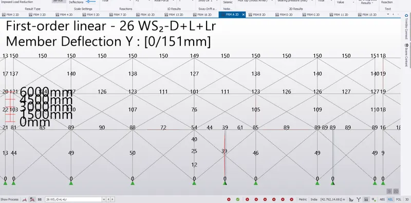
above Screenshot is subset of FrameA; taken at the central portion which seems to be more critical in terms of Deflection on either side of the Frame.( Grid 6-12) is shown above where deflection seems to be ambiguous .
==============================================================
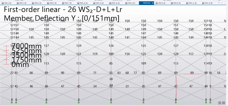
Frame B, taken in b/w Grid (6-12).
=========================================================================
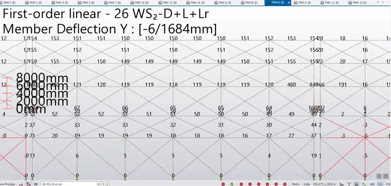
Frame D, frame containing the gantry Girder Column in b/w Grid 6-12.
===========================================================================

Frame G, taken in b/w Grid 6-12.
=============================================================================
Summary:
Above Model is unstable in Y direction due to absence of providing any lateral support in Y direction, resulting in huge deflection in the central portion (Grid 6-12) as shown in above Frame (A, B, D & G).
measures taken to remove the unstability in Y direction, but nothing works :
1. By providing Lateral Restraint (Top * Bottam Flange restraint) along the length of Column members by dividing the column length in four stacks.
2. By providing Strut along the column length.
3. By providing the haunches at the arm containing Gantry Support (Cantilever Length of 1 m on Frame B & D)
4. By Increasing the memberof column size taken from (UK h=350, bf=202, zp=3955mm3).
5. After modifying the model, followed by (Save Option), modification made are gone out after switching off the software own its own.
===============================================================================
Thanks & Regards
Failed to answer the question.
Please let me know about yr viewpoint to make this correct in terms of all respect though major challenge here
Unstability along the width of the frame (Y axis).