Project 1_Analyze and design a steel building to 10T CRANE as per IS standard code using TEKLA STRUCTURAL DESIGNER.
AIM:- Analyze and design a steel building to 10T CRANE as per IS standard code in TEKLA STRUCTURAL DESIGNER. Refer the attached plan and elevation. Provide bracings and moment connection for lateral stability.
Consider dead, live, equipment and wind loading. Consider the brick wall loading for 150mm thick and 1.5 KN per sq m for wall and roof cladding.
Assume wind loading basic speed as 39m/s
Report of each member to be generated and extract drawings of structural plans from the software
INTRODUCTION:- Tekla Structural Designer software is used for analysis and design of structures. In the first step we model the structure, then we apply dead load, live load, wind load, seismic loads to the modelled structure.
PROCEDURE:-
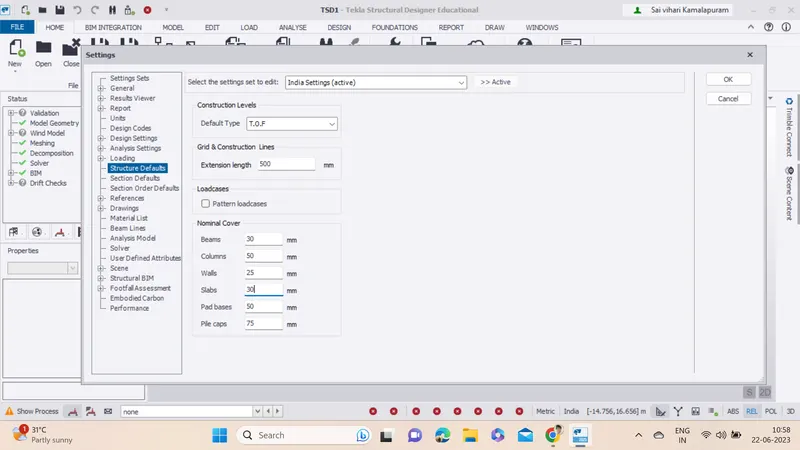
1. Open Takla structural designer software, New file is createdn and saved with Project1 name and then the settings are selected to specify the units, codes and structure default settings.
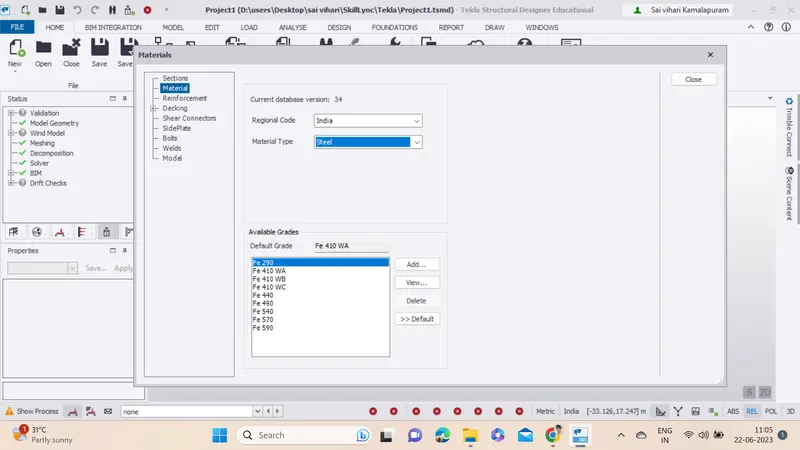
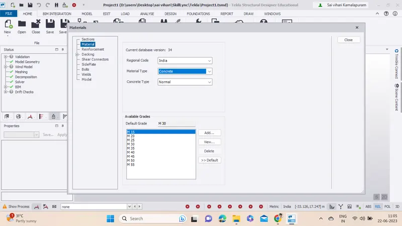
2. Next step is we go to the Materials options and then we specify the concrete grade and steel etc.
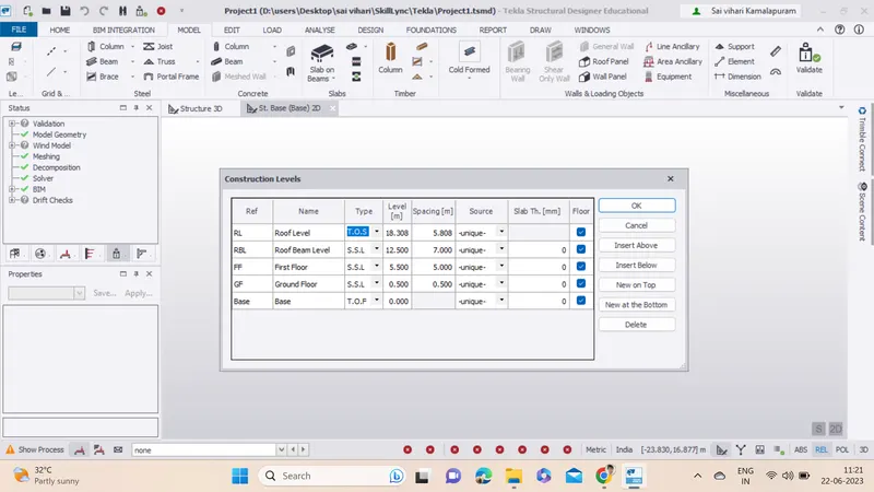
3. Next step we need to create construction lines. We go to the Construction levels.
- From the assignment files we get the heights of the structure using that we now specify the construction levels as Roof Level, Roof Beam Level, First Floor, Ground Floor, Base.
- We need to find the height of roof level assume roof angle as 17 deg
- tan 17 = Height of the roof / (Span / 2) = H / (38000/2)
- Therefore, H = tan 17 * 19000 = 5808mm = 5.808 m
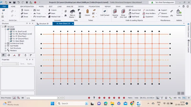
4. Next step we need to draw Grid lines. One line is placed and parallel option is used to draw rest of the lines easily.
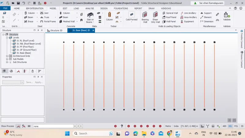
5. In the same manner we draw horizontal grid lines from A-G giving the spacing according to the given plan layout.
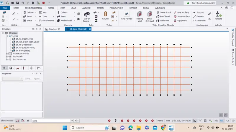
6. A construction line is drawn in between D and E using parallel construction line.
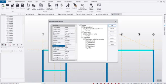
7. Next step is that we need to Go to Home - Manage Property Sets - New - Materials - Concrete Column.
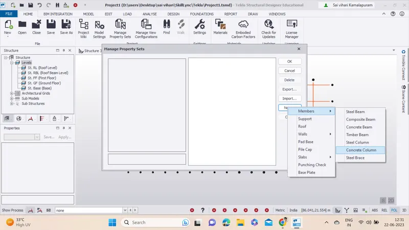
8. Create a pedestal of size 500x1000 mm, major alignment should be centre and the releases are fixed at both ends top and bottom. Name is given as Pedestal column.
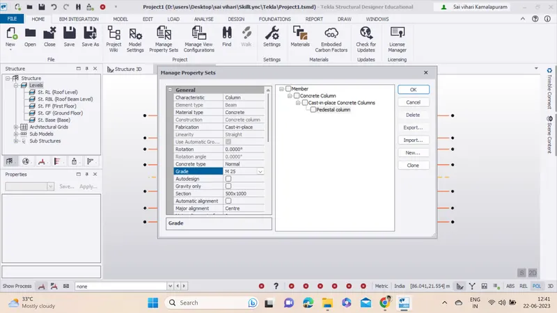
9. Now we need to assign the columns on the grid lines, For that we need to go the Model - Concrete - Column
From the properties window we select the column and then we place it.
10. Next step we need to create Steel columns, We Go to Manage Property sets -> New -> Steel Colu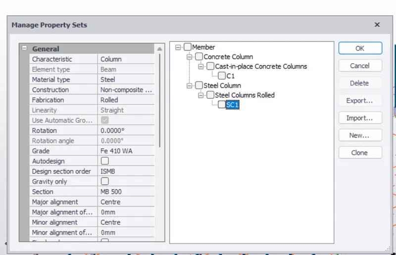
11. We need to now place the steel columns. From the properties window we select the column and then we place it.
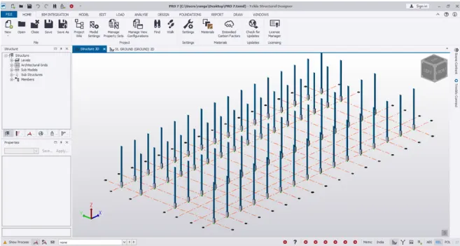
12. Here now we want to place the Beam. So first taken the manage properties set option, next go to the new option
13. Then select the menbers and select steel beam now rename it as steel Beam 1. We need to modify the general setting what we want like size as been MB 350
14. And place the steel beam on the vertical grid direction again create beam with another size and place it where we want.
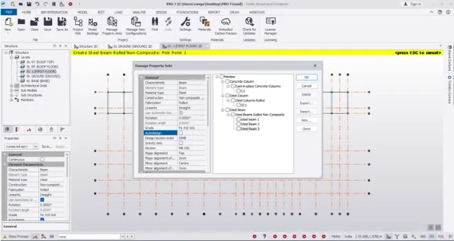
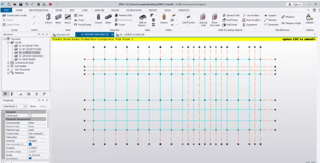
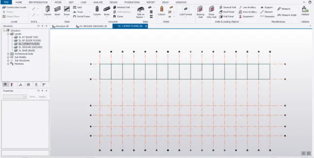
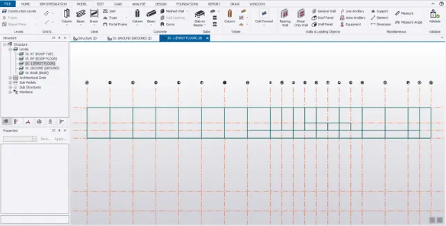
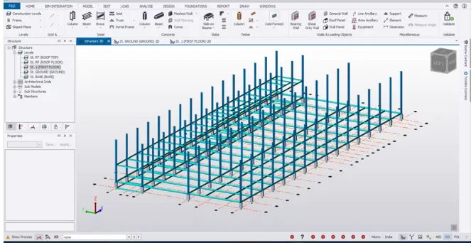
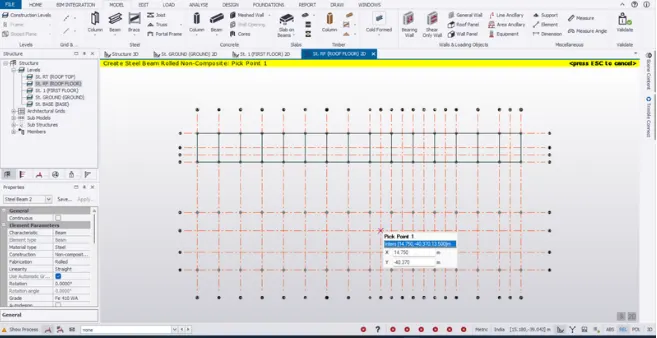
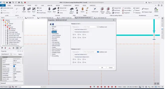
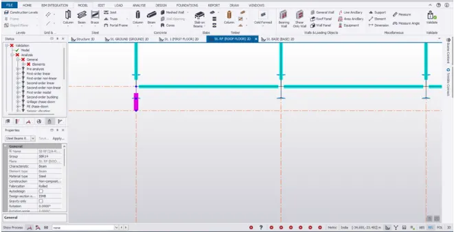
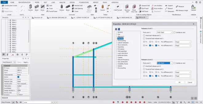
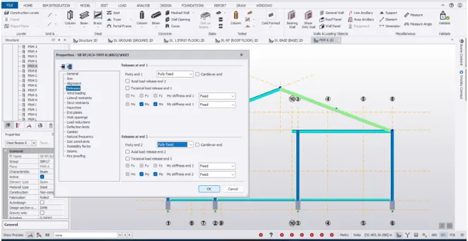
15. Next we want to make crane cantilever beam in between the gird 2 and 3 at roof floor just parallel the grid to 1m distance and make a cantilever beam on grid 2 and 3 to 1m distance and if u validate it , its shows some error
16. So double click the beam and set the 2nd end at cantilever and the ok, next copy the beam and place at all the girds where we want, next we want to make a bracing
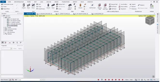
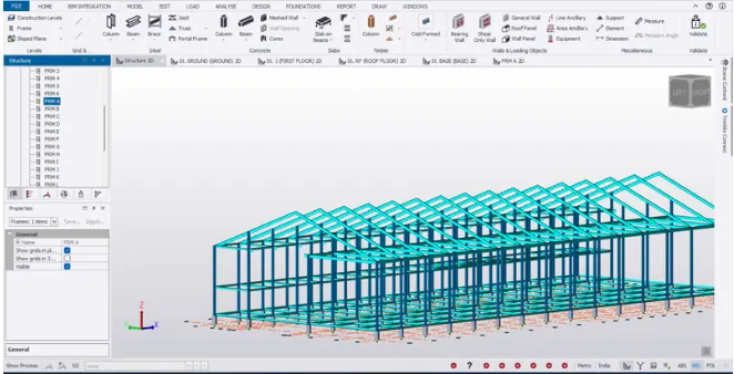
17. After creating the rafter beam, then next go to the model tab, select the frame option, set the 3d screen
18. Now place the frame on the all the grid option, then the frame as been created automatically. Go to the structure box on the left side of the screen, then select the frame option and select the frame what we want.
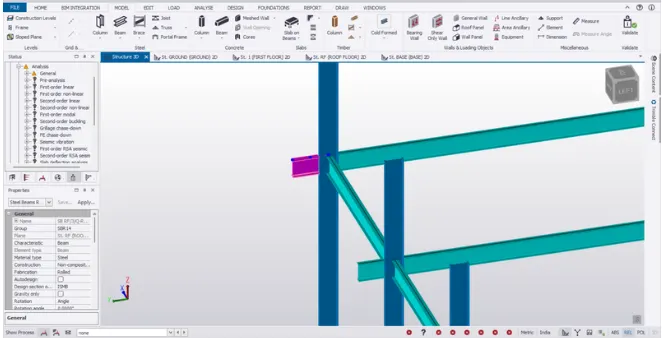
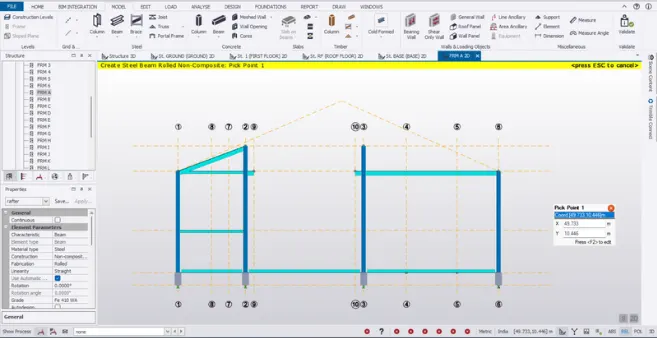
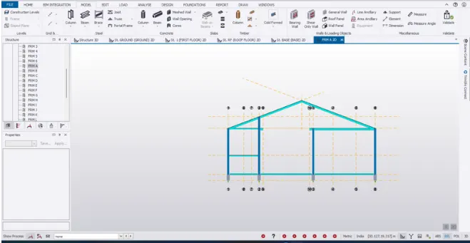
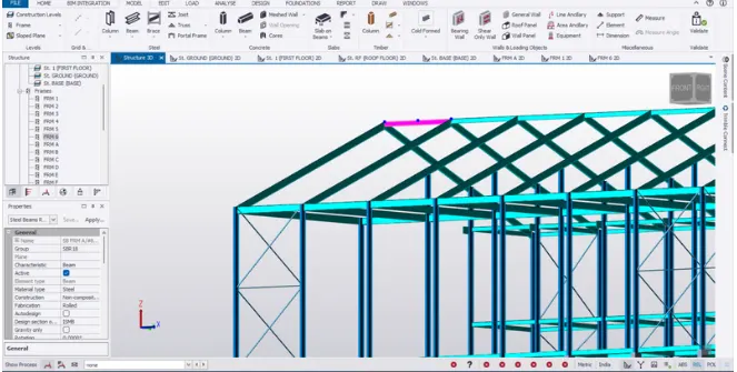
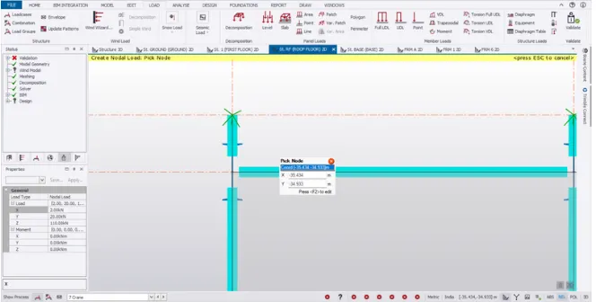
19. Go to the model tab, select the construction line and pick the frame A, draw the construction line at mid point of 1 to 6, draw the rafter beam on the grid with cone shape
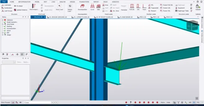
20. The rafter beam as been shown in below the image. Select the rafter beam and right click and copy the beam, pick the reference line and copy to all the grid
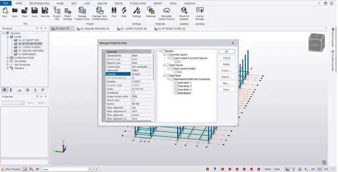
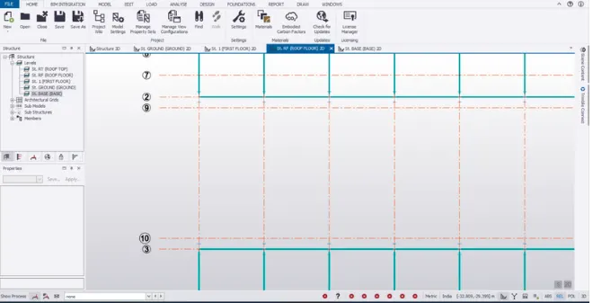
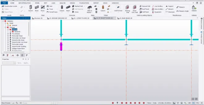
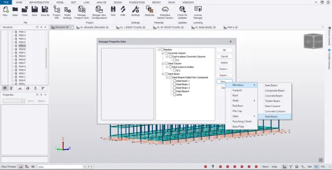
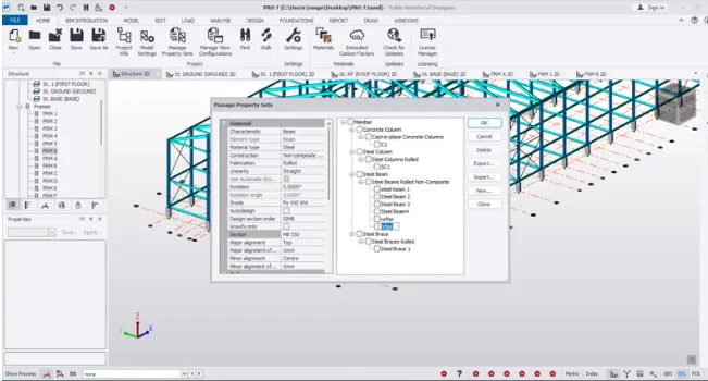
21. Now we need create bracings, so go the home tab and select manage property set. Next we pick the new option and select members and pick the steel brace option,
Go to the General setting -> Section option
Select the equal angles and select the 75 75 5 6 8 10
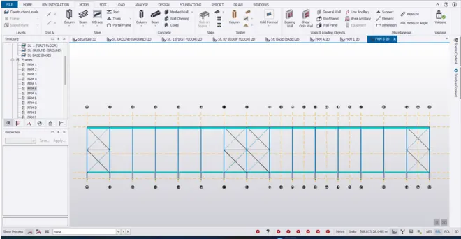
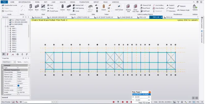
22. Select the X brace option on the model tab. Go to Properties box -> Created brace option -> Go to the frame
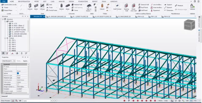
And draw the X brace on the floor. And turn the screen on 3d and draw the X brace on the roof top. The completed brace image as been shown below. Next go to the roof panel option, place the roof panel on the top of the roof
23. The roof panel placed image as been shown below, next we want to make slab on the beam, so go to the manage properties sets and make new slab and give a values, we now place the slab on beam.
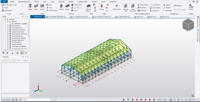
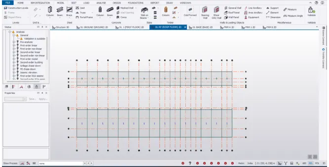
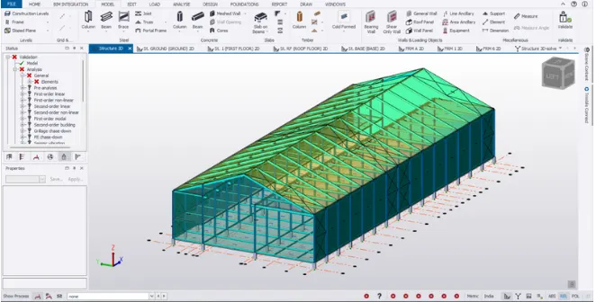
24. Now we need to create loads on the model.
Calculation of Dead loads :
. Brick wall thickness = 150mm
. Height of the wall = 5m
. Unit weight = 20 KN/m^3
. Brick wall loading (gf) = 0.15 x 20 x 5 = 15 KN/m
. Brick wall loading (ff) = 0.15 x 20 x 7 = 21 KN/m
. Unit weight of concrete = 24 KN/m^3
. Finishes = 50mm x 24 KN/m^3 = 0.05 x 24 = 1.2 KN/m^2
Floor height :
. Assume floor finish thickness = 50mm
. floor finish = 0.05 x 24 = 1.2 KN/m^3
. Roofing load based on purlin size : 1.5 KN/mm^2
. Ceiling load of 0.3 KN per sq m
Calculation of Imposed load :
. The live load has been considered by IS 875 PART 2
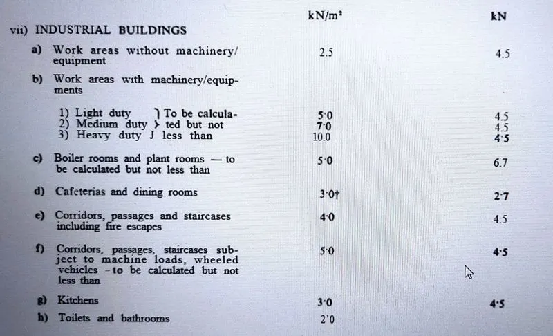
25. Now we need to calculate the given crane load.
Calculation of crane load :
GIVEN :
. Crane capacity= 100 KN
. Weight of crab = 35 KN
. Weight of crab = 160 KN
. Weight of trolley car = 10 KN
. The approximate minimum approach of the crane hook to gantry girder = 1m
. Span of crane girder (c/c of wheel) = 20 m
. Span of granty girder (c/c of wheel) = 6 m
. Self weight of the crane = 160/2 = 80
. Wheelbase = 3m
SOLUTION:
1.) Maximum wheel Ioad
1. Maximum concentrated load on crane = 35 + 100 = 135 KN
2. Self weight of crane will act as uniformly distributed load of intensity = 35 /10 = 3.5 KN/m
Taking Moment about B
(RA X 20) - (135 X 19) - (8 X 20 X 10) = 0
RA = 208.25 KN
Taking Moment about
RB = 295 - 208.25 = 86.75
RB = 86.75 KN
| RA + RB = 295 KN |
The reaction of the crane gider is distributed equally on two wheel at the end of the crane girder.
Maximum wheel load on each wheel of crane (RA/2) = 208.25/2 = 104.12 KN
2.) Maximum Bending Moment:
Assume self-weight of gantry girder as 1.5 KN/m
Assume self-weight of rail as 0.3 KN/m
Total dead load = 0.3 + 1.5 = 1.8 KN/m
At D :
(RC X 6) = 104.12 X (2.25+3) + 104.12 X 2.25
RC = 130.15 KN
At C :
RD = 78.09 KN
| RC + RD = 208.24 KN |
Bending Moment under a wheel load due to live load
RD X 2 = 78.09 X 2 = 156.18 KNm
Bending moment due to impact = 0.10 X 156.182 ( 10 % due to M.o.T) = 15.61 KN m
Total bending moment due to live load and impact load = 171.79 + 8.1 = 179.89 KNm
Bending moment due to dead load WI^2/8 = 1.8 X (6 x 6) /8 = 8.1 KNm
Maximum bending moment = 179.89 + 8.1 = 187.99 KN m
3.) Maximum shear force:
At D : (RC X 6) - (104.125 x 6) - (104.125 x 3) = -312.375 RC = 156.18 KN
Hence the Maximum shear force due to wheel load is = 156.18 KN
Lateral Forces : Lateral force transverse to rails = 5% of the weight of crab and weight lifted = 0.05 x (1.125) = 2.25 KN
Lateral forces each wheel F1 = 2.25/2 = 1.125 KN
Maximum horizontal reaction due to lateralforce by proportion at C
= Lateral force x reaction at c due to vertical load / Maximum wheel load due to vertical load
= 1.125 x 156.18 / 104.12
= 1.68 KN
Horizontal reaction due to lateral force by proportion at D 2.25 - 1.68 = 0.57 KN
Bending moment due to lateral load = (1.125 / 104.12) X 130.15= 1.406 KNm
26. Now we need to calculate the wind load on the model.
Calculation of WIND load :
Given Data : Basic wind speed = 39m/s Terrain category 2 .
. Total length of the building (l) = 90m
. Total width of the building (w) = 38m
. Total height of the building (h) = 16.5m
. Class of the structure = Class A
. Life of the structure = 50 Years
. l/w = (90/38) = 2.36
. h/w = (16.5/38) = 0.43
STEP :1 EXTERNAL PRESSURE CO-EFFICIENT (Cpe)
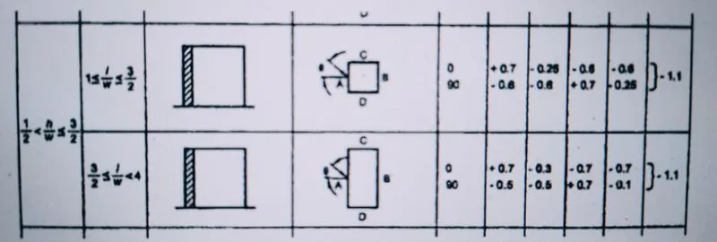
As per the IS 875 Part 3, Table 5
Building height ratio
Building height ratio = 1/2
Therefore, the building plan ratio = 1
Hence the plan we choose is given below
STEP :2
Finding the Factors (k1, k2, k3, k4)
k1: From Table 1 for the basic wind speed for 39 m/s,
Risk Coeffiecent, K1 = 1.0
K2 : From Table 2, 10m height = 1 for terrain category 2
15m height = 1.05
by using the interpolation method,
k2 = 1.02
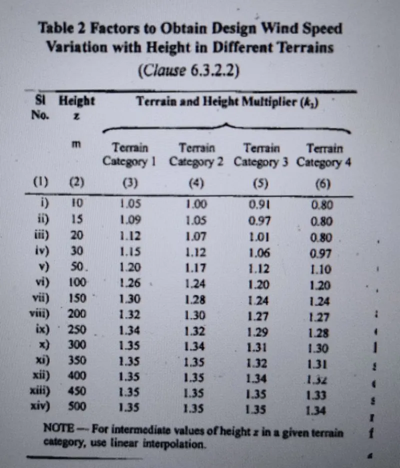
K3: Topography factor, k3 = 1 (from clause 6.3.3)
K4: Importance factor K4 = 1.15 (from Clause 6.3.4)
STEP :3 Vz=Vb x k1 x k2 x k3 x k4
= 39x1x1.02x1x1.15
= 45.747 m/s
STEP :4
Pz = 0.6 Vz^2
= 0.6 x 45.747^2
= 1255.6728 n/sq.m
= 1.2556 kn/sq.m
STEP :5 Wind direction (up to roof level)
1.) Wind direction along y- direction (Face C & D):
| Cpe + | Cpi - | |
| Height of the building | 16.5m | 16.5m |
| External pressure co-efficient Cpe | -0.6 | -0.6 |
| Internal pressure co-efficient Cpe | 0.7 | -0.7 |
| Net pressure co-efficient Cp = Cpe - Cpi | 1.3 | 0.1 |
| Design wind pressure, Pz | 1.2 | 1.2 |
| Wind load on Wall (Cp x Cz) Kn/m^2 | -1.625 | 0.125 |
2.) Wind direction along X- direction (Face A):
| Cpe + | Cpi - | |
| Height of the building | 16.5m | 16.5m |
| External pressure co-efficient Cpe | 0.7 | 0.7 |
| Internal pressure co-efficient Cpe | 0.7 | -0.7 |
| Net pressure co-efficient Cp = Cpe - Cpi | 0 | 1.4 |
| Design wind pressure, Pz | 1.2 | 1.2 |
| Wind load on Wall (Cp x Cz) Kn/m^2 | 0 | 1.75 |
3.) Wind direction along X- direction (Face B):
| Cpe + | Cpi - | |
| Height of the building | 16.5m | 16.5m |
| External pressure co-efficient Cpe | -0.25 | -0.25 |
| Internal pressure co-efficient Cpe | 0.7 | -0.7 |
| Net pressure co-efficient Cp = Cpe - Cpi | -0.95 | 0.45 |
| Design wind pressure, Pz | 1.2 | 1.2 |
| Wind load on Wall (Cp x Cz) Kn/m^2 | -1.187 | 0.562 |
STEP :6
Roof Calculation: W.k.t
h/w = 0.6
In order external coefficient from the table 6
Slope = Sin theta = opp/hyp
= 2.813/8.939
theta = 18.34
by using interpolation method
(18.34-10)/ (20-10) = (x+1.2)/(-1.4+1.2)
therefore, x =-1.36
Similarly
(18.34-10)/(20-10) = (x+0.4)/(-0.4+1.4)
X = -1.24
Hence, EF = -1.36
FG = -1.24
STEP :7
1.) Wind direction along Y- direction (Face EF):
| Cpe + | Cpi - | |
| Height of the building | 16.5m | 16.5m |
| External pressure co-efficient Cpe | -0.4 | -0.4 |
| Internal pressure co-efficient Cpe | 0.7 | -0.7 |
| Net pressure co-efficient Cp = Cpe - Cpi | -1.1 | 0.3 |
| Design wind pressure, Pz | 1.2 | 1.2 |
| Wind load on Wall (Cp x Cz) Kn/m^2 | -1.375 | 0.375 |
2.) Wind direction along y- direction (Face GH):
| Cpe + | Cpi - | |
| Height of the building | 16.5m | 16.5m |
| External pressure co-efficient Cpe | -0.4 | -0.4 |
| Internal pressure co-efficient Cpe | 0.7 | 0.7 |
| Net pressure co-efficient Cp = Cpe - Cpi | -1.1 | -0.3 |
| Design wind pressure, Pz | 1.2 | 1.2 |
| Wind load on Wall (Cp x Cz) Kn/m^2 | -1.375 | 0.325 |
27. Now we need to apply the loads on the Tekla structural design model.
APPLY THE LOAD ON TSD :
. Go to the load tab -> Pick the load cases option
. In there create a new loads like dead, imposed, wind, crane, servises, seismic..,
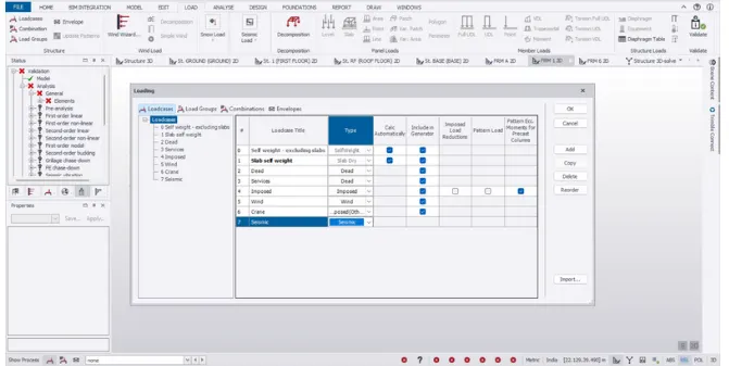
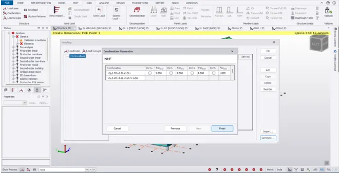
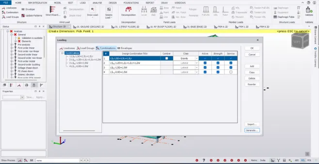
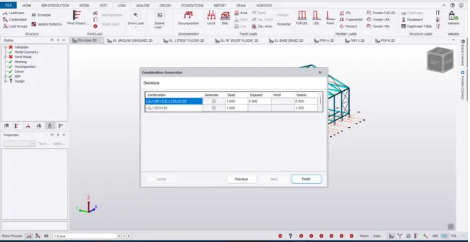
. Go to the load combination -> Go to the generate option on the load combination dialouge box
. And select the 1st option and select next
. Again give the next option as 2 time and finally pick the finish option
. The load combination as generate sucessufully
. Next we want to apply the dead load
. So go to the below the screen on show process option
. And select the dead load option
. Next go to the home tab and select the manage properties set
. And select the new option and select the slab items and rename it as (one way slab and two way slab)
. Next go to the slab on beam option and select the slab item on general box
. As per the IS rules apply the one way slab and two way slab on the floors
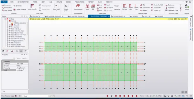
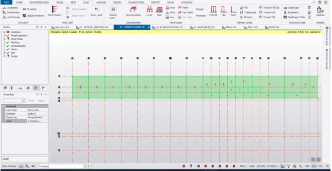
. Next go to the area load
. apply the loads on room as per same IS rules for all the floors
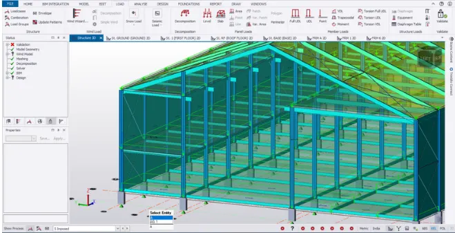
. After complete the load applyed on all the floors
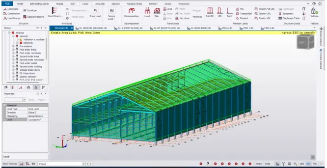
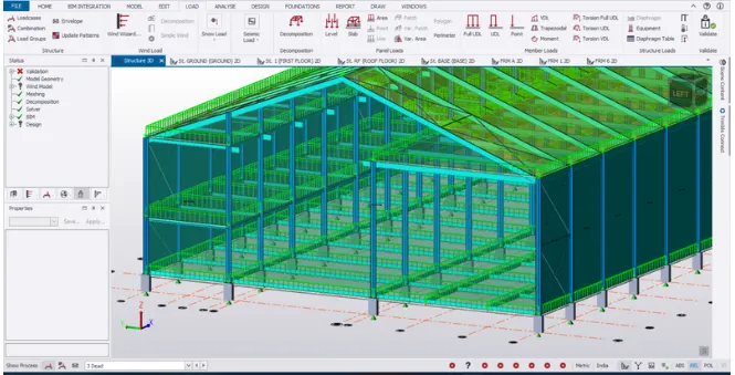
. Next apply the load on roof panel
. The load applyed image as been shown below
28. Next we want to apply the imposed load. The same process go to below the screen "show process" set the imposed load, next go to the area load on top of the screen
29. For the all individual rooms have individula live load are there, it as been the IS rules, so we want to check the all the rooms live load and apply as per the IS rules the applyed imposed load as given in below the image, the same process applyed all the floors
30. Open tekla software and here we want to set the crane load, so go to the crane load option on below the screen, next go to the load tab
31. Pick the point load and go to the left side of general box, in there set the load type as nodal and give the value we derived next go to the crane lifing beam and apply the load
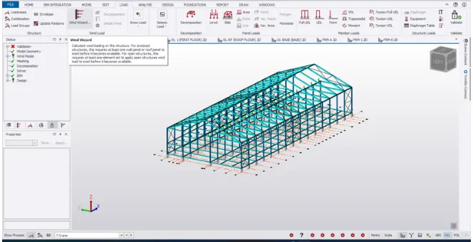
32. Deleted all the previous wind load as been created in above next go to the wind wizard option on under the load panel ,after wind wizard box as been appear, select the worst case data and unselect the (data for each direction and clade frame) --> Next
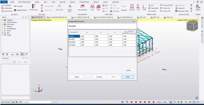
33. Give the wanted value on basic data box and click next, apply the fetch distance 10 and click next and click next on topography box and results box
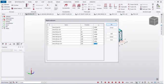
34. Add the wind load on (load cases box). Go to the seismic load -> Select the code spectra on (site specific spectra box) select next and given the basic information and select next, Pick the next botton on structural irregularites. Select the rc steel concrete on fundamental period
Select the steel building with OMRF on (Seismic force resisting system box) and pick next again give the next botton and click finish
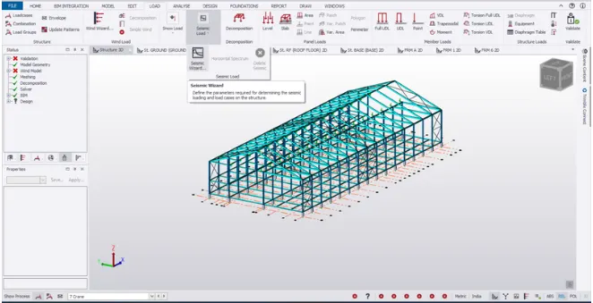
35. Open the tekla software and open the file previously created.
Go to the load tab -> Select the seismic load
Select the code spectra and then click on Next option
. Basic information --> Next
. Structural irregularties --> Next
. Fundamental period --> Next
Seismic force resisting system --> Steel building with OMRF --> Next
Effective seismic weight --> export all load to right side --> Next
Localization --> Next
Initial parameters --> Replace only combination --> Next
Combination --> Next
Service --> Next
36. Next Go to the Analysis tab -> Pick the setting option
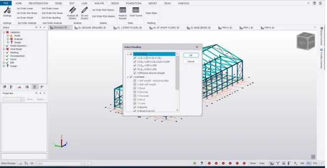
In there select 1st order non-linear and check once 100 and 0.01% and also check the concrete and general option once then click ok, finally pick the analysis option and select the 1st order linear, select all combination and load cases option and then click ok
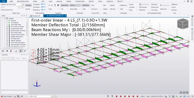
37. Go to the ground floor and select the result tab and also select the deflection and select the load cases, then we want to check the moment major, shear major, and Axial force. Select the frame 3 and check the deflection. Select one beam and then right click
38. Go to the Check member -> Static
. If we get a error we need to change the properties
39. Now again analysis the model and go to the same beam and right click and select the Check member -> Static
. Now all members are passed
40. Now select the taken a passed beam go to the review screen and use the copy monitor option. Copy the passed beam to other failed beams
41. Finally all beams are passed next we want to check the column
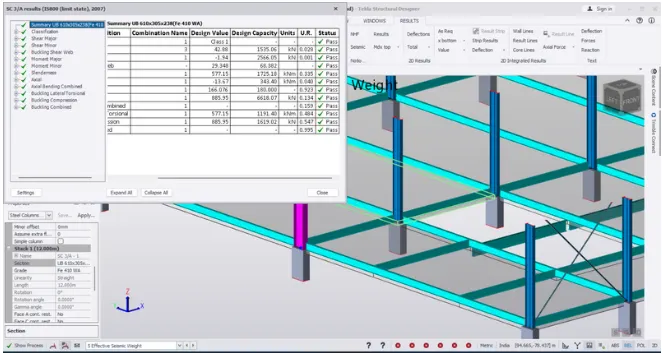
42. Select the column And right click the column and select Check member -> Static
. If we get a error we need to change the properties
43. So Go to the column properties template and change the section ISMB (Indian - UK) and select 610X305X238 Then OK
After check with using Check member -> Static and my column as been passed
44. Again using the copy monitor option and copy all passed column to failed column
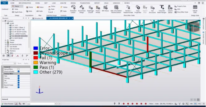
RESULT : Using the TSD software we analyzed and designed a steel building with 10T CRANE load.
We created concrete columns.
We created steel columns.
We created beams.
We created bracings.
We created roof panels.
We applied dead loads, live loads, wind loads.
Finally analysis is done and changes are made to pass the tests.