Project 1_Analyze and design a steel building to 10T CRANE as per IS standard code using TEKLA STRUCTURAL DESIGNER.
Aim:- To analyze and design a steel building as per IS standard code
Given data:-
- assuming the wind speed as 39 m/s
- thickness of the wall as 150mm
- wall and roof loading to be considered as 1.5 Kn/m^2
- live loads and equipment loads should be assumed as per IS 875 part 2
- wind load calculated as per IS 875 part 3
Step 1:- To model the structure
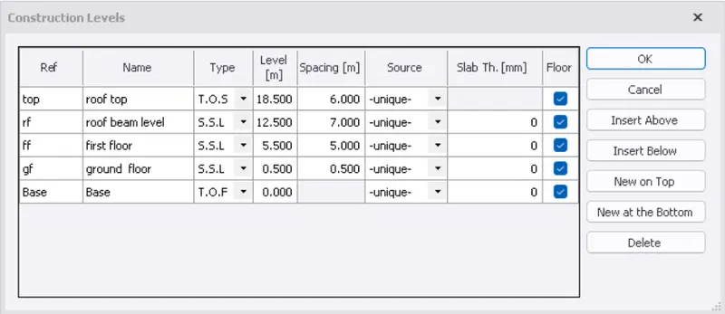
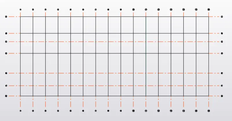
- to define construction levels
- click on the construction levels icon in the model toolbar
- define the levels as per the details given in cross section
- to define gridlines
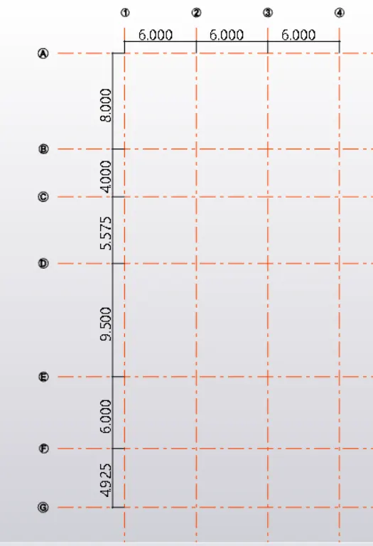
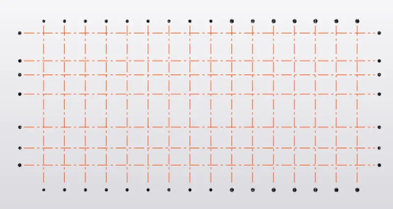
- click on gridlines icon in the model toolbar
- specify the first point and draw the first grid line
- then select parallel quick option and draw all other gridlines by specifying the distance
- to add supports to the column base
- to add concrete pedastals to the column base
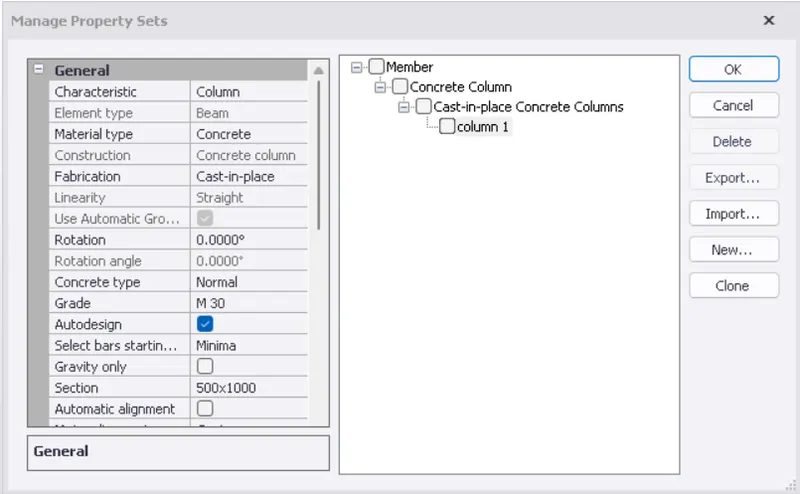
- go to manage property sets from the home toolbar
- click on new> concrete column
- modify the propeties of the concrete column and click on ok
- now go to model>click on column> precast
- select the column properties from the properties dialoguebox
- assign them to the column base
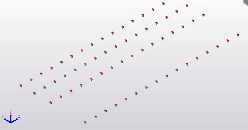
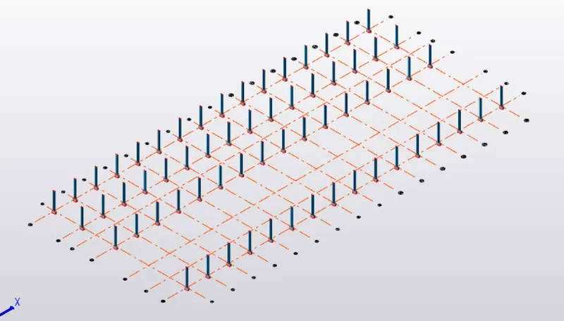
- to assign steel columns
- go to manage property sets>new> steel column
- now select the cross section of the steel column
- add columns to the model
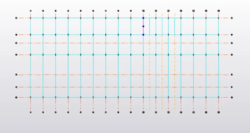
- to model beams
- define the properties of the beam in manage property sets
- assign them to the model
Beam layout in groundfloor level
Beam layout in firstfloor level
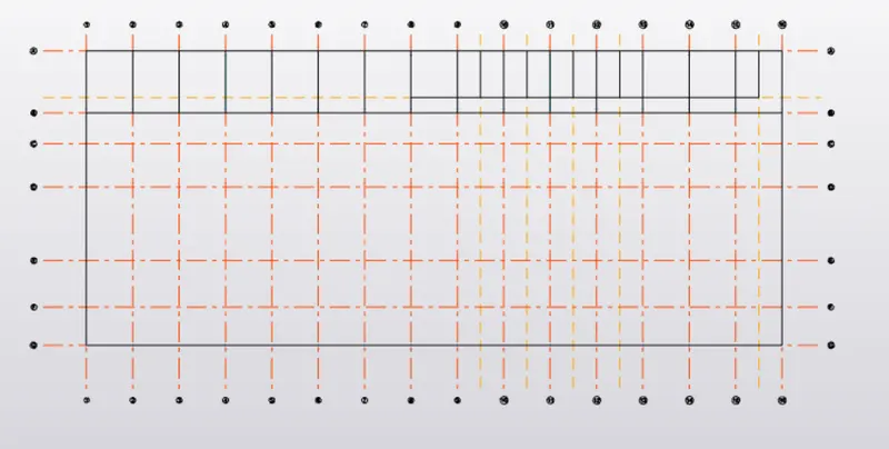
Beam layout in roofbeam level
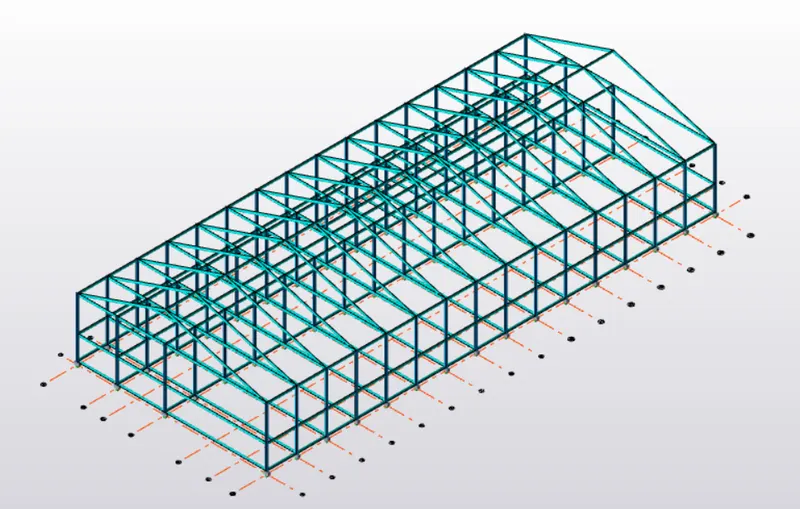
Structure with beams, columns and rafter beams
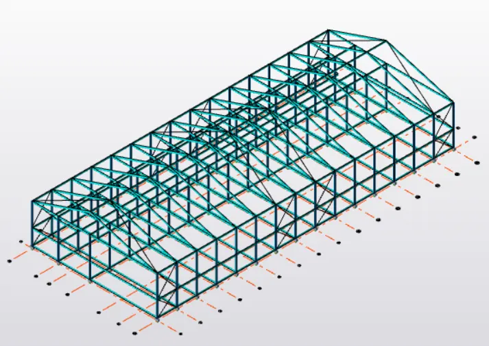
- To add bracing to the wall and roof
- go to manage property sets > new> steel brace
- select the section of the brace element
- go to model >click on brace
- then add bracing to the model
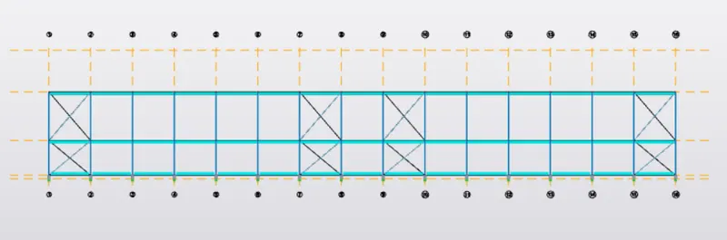
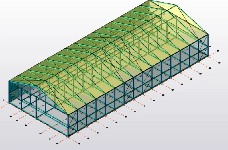
- roof bracing are added in 3d view
- to add slab panels to the model
- check whether the slab is one way or two way
- then go to manage property sets>slabs
- select the grade of the concrete and define the depth of the slab panel
- then assign the slab panels to the model
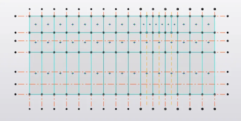
slab panels at ground floor level
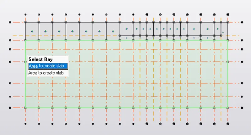
slab panel at first floor level
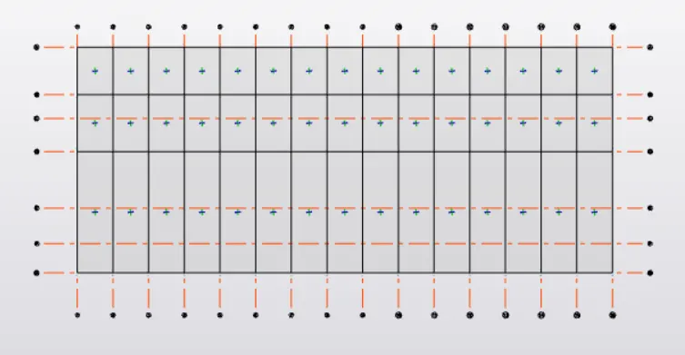
slab panel at roof beam level
- to add wall panels and roof panels to the model
- to add load cases
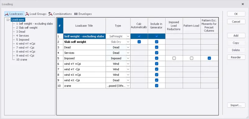
LOAD CALCULATIONS
Calculation of brick wall load
- assume the unit weight of the brick as 20 kn/m^3
- height of the brickwall is 5m
- thickness of the brickwall is 150mm
- load of brick wall is 20 x 5 x 0.15 = 15 kn/m
- brick wall load on first floor beam is 7 x 20 x 0.15 = 21 kn/m
Calculation of floor finishes
- assume the thickness of the floor finishes as 50mm
- unit weight of the floor finishes is assumed as 24 kn/m^3
- floor finishes load is 0.05 x 24 =1.2 kn/m^2
Calculation of imposed loads
- imposed loads are considered as per IS 875 part 2 based on occupany
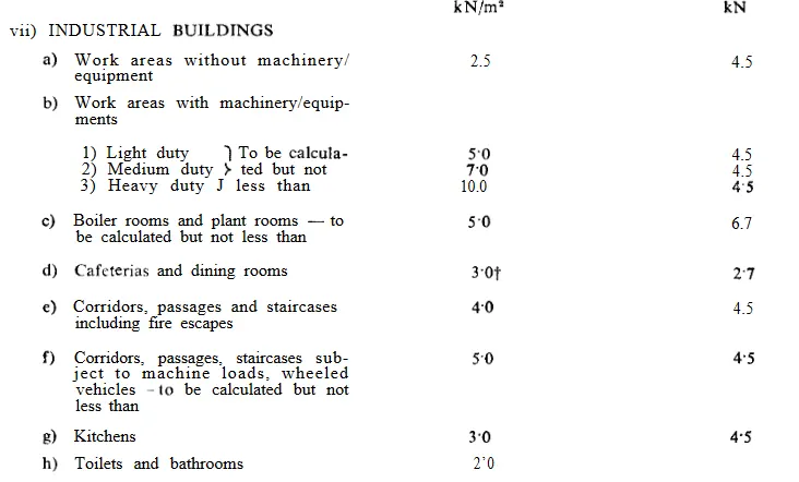
Calculation of wind loads(as per IS 875 part 3)
- basic wind speed is considered as 39 m/s
- assume the design life of the structure as 50 years
- terrain category as 2
Design wind speed
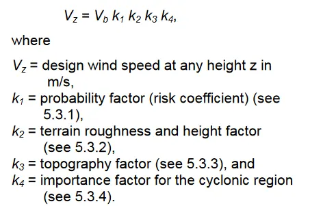
- K1 probability factor is assumed as 1 (as per IS 5.3.1)
- K2 terrain and height factor is assumed as 1
- K3 topography factor is assumed as 1 (for slope of structure greater than 3)
- K4 importance factor for industrial building is taken as 1.15
design wind speed Vz = 39 x 1 x 1 x 1.15 x 1
design wind speed = 44.85
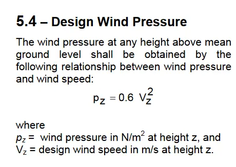
design wind pressure Pz =0.6 x 44.85^2
design wind pressure 1206.9 N/m^2= 1.2 kn/m
- total length of the building is 90m
- width of the structure is 38m
- height of the structure is 12.5m
Ratio of wall and roof co efficients
l/w = 90/38 = 2.36
h/w = 12.5/38 =0.328
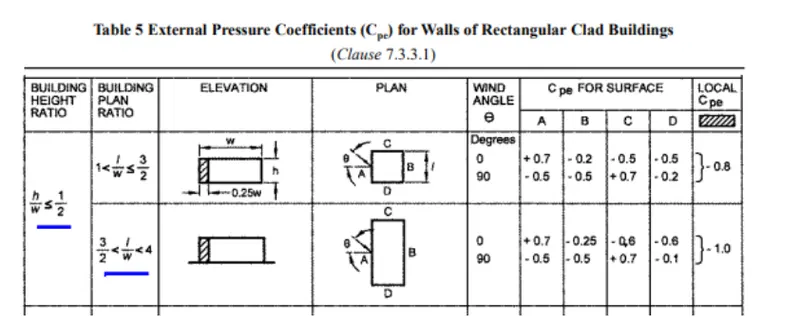
wind load calculations( +Y direction face A )
+Cpi -Cpi
external pressure coefficient 0.7 0.7
internal pressure coefficient 0.7 -0.7
net pressure coefficient 0 1.4
design wind pressure 1.2 1.2
loading to be applied on the wall 0 1.75
wind load calculations( +Y direction face B )
+Cpi -Cpi
external pressure coefficient - 0.25 -0.25
internal pressure coefficient 0.7 -0.7
net pressure coefficient -0.95 0.45
design wind pressure 1.2 1.2
loading to be applied on the wall -1.187 0.562
wind load calculations( +X direction face c )
+Cpi -Cpi
external pressure coefficient - 0.6 -0.6
internal pressure coefficient 0.7 -0.7
net pressure coefficient 1.3 0.1
design wind pressure 1.2 1.2
loading to be applied on the wall -1.625. 0.125
wind load calculations( +X direction face D )
+Cpi -Cpi
external pressure coefficient - 0.6 -0.6
internal pressure coefficient 0.7 -0.7
net pressure coefficient -1.3 0.1
design wind pressure 1.2 1.2
loading to be applied on the wall -1.625. 0.132
Roof load calculations
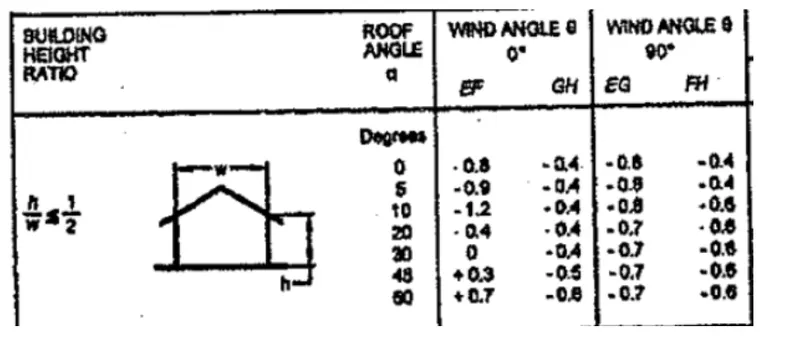
wind load calculations( +y direction face EF )
+Cpi -Cpi
external pressure coefficient - 0.4 -0.4
internal pressure coefficient 0.7 -0.7
net pressure coefficient -1.1 0.3
design wind pressure 1.2 1.2
loading to be applied on the wall -1.375. 0.375
wind load calculations( +y direction face GH )
+Cpi -Cpi
external pressure coefficient - 0.4 -0.4
internal pressure coefficient 0.7 -0.7
net pressure coefficient -1.1 0.3
design wind pressure 1.2 1.2
loading to be applied on the wall -1.375. 0.375
Crane load calculations:-
crane capacity =100kn
weight of the crab = 35kn
weight of the crane = 160kn
max hook approach = 1m
wheel base= 3m
distance between c/c gantry rails =20m
distance between c/c gantry columns= 6m
max point load on the crane = 100 +35= 135
self weight of the crane = 160/2 = 80
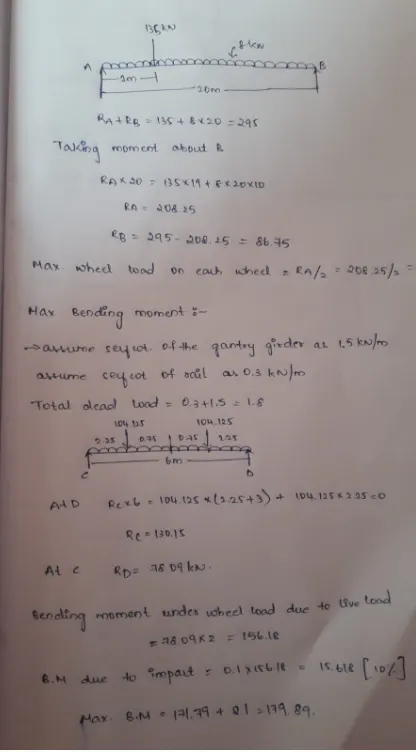
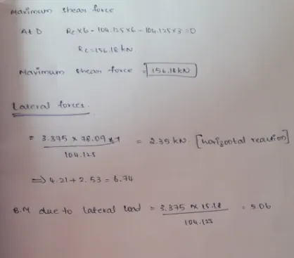
TO ASSIGN LOADS TO THE MODEL
brickwall loading and live load on floor assigned on ground floor
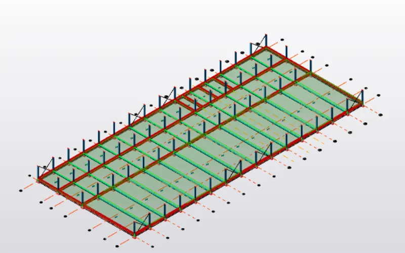
brickwall loading and live load on floor assigned on first floor
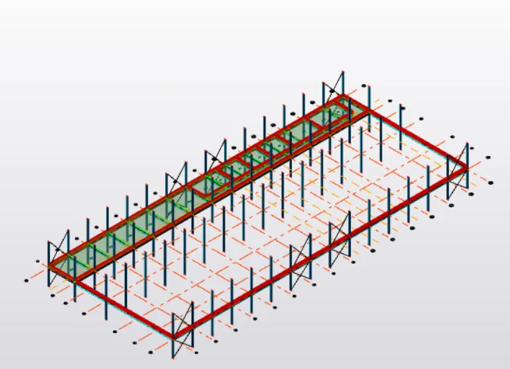
- for 18 degres pitched metal roof
- imposed load on the roof is 1.5
To assign wind loads
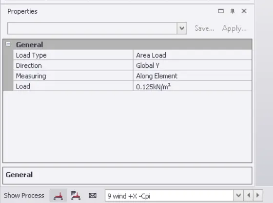
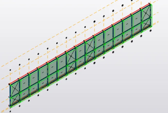
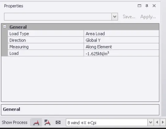
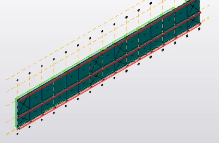
wind loads assigned on roof top

after assigning all the loads
validate the model and run the analysis
before analysing the model check the modifications of the first order linear analysis from the setting toolbar
then go to analyisis toolbar and click on analyze
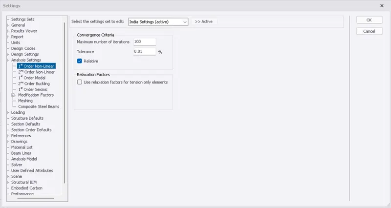
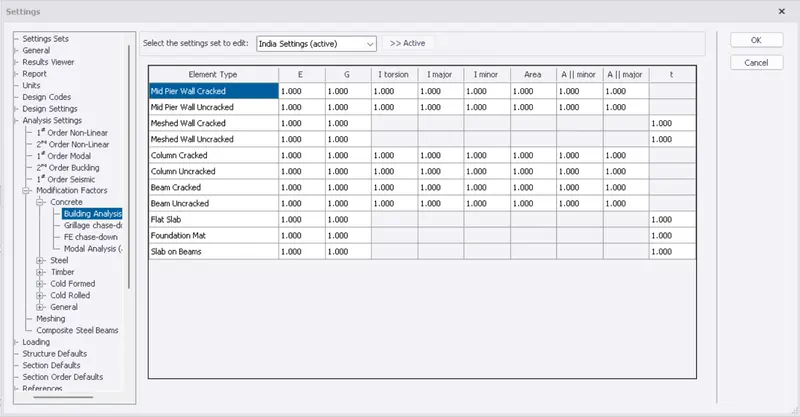
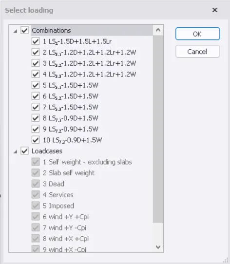
after the analysis is done we can view the failue criteria of the structure
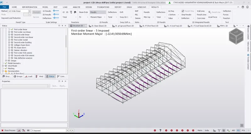
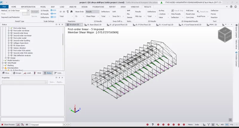
RESULTS:- the structue is modeled ana analyzed and designed for all the load combinations