Project 1
INTRODUCTION-
AHMEDABAD METRO RAIL PLATFORM IN KANKARIYA BLOCK had 260m of length and 22m of width. The structure is in underground structure with a depth of 20m from the ground level to wall toe level. A typical section of the platform (Section B-B) having 10m length is provided for defining the different types of loading i.e. (Deal Load, Live Load, Earth Pressure Load, Wind Load, Seismic Load) acting to the structure.
Given Data:
1. Area of the wall = 0.75m x 20 m
2. Area of Roof Slab = 1m x 22m
3. Area of Concourse Slab = 1.2m x 22m
4. Area of Platform Slab = 0.7m x 13.5m
5. Area of Indicative Structural Member = 0.6m x 2.5m
6. Area of Base Slab = 2m x 22m
7. Area of Rectangle Track Member = 0.75m x 2m
8. Unit weight of soil (γ) = 18kN/m3
Dead Load Calculations:
1. Self weight of wall = 0.75x20x25 = 375 kN/m
2. Self weight of Roof Slab = 1.0x22x25 = 550 kN/m
3. Self weight of Concourse Slab = 1.2x22x25 = 660 kN/m
4. Self weight of Platform Slab = 0.7x13.5x25 = 236.25 kN/m
5. Self weight of Indicative Structural Member = 0.6x2.5x25 = 37.5 kN/m
6. Self weight of Base Slab = 2 x 22 x 25 = 1100 kN/m
7. Self weight of Rectangle Track Member = 0.75x2x25 = 37.5 kN/m
Total Dead Load = 2996.25 kN/m
Live Load :
IRS Metro Live Loading is given:
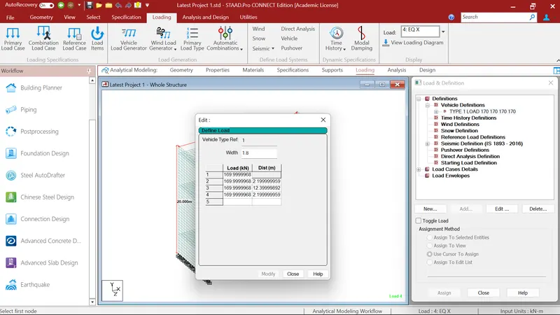
As per IRS Metro Live Loading have total 540kN of axle load. In the first axle there is 170kN load at a distance of 2.2m as shown in picture and so on. Metro Train having 1.8m of width.
EP Load Calculations:
As the structure is in underground with a depth of 20m from G.L to Wall Toe Level. So, active earth pressure will acting on the walls.
Active earth pressure = Ka x γ x h
= 0.35 x 18 x 20
= 126 kN/m2
Wind Load Calculation as per IS 875: Part-III:
As our structure is underground so there will be no effect of wind loading. But for question is asking for wind load calculation here is the mannual calculation.
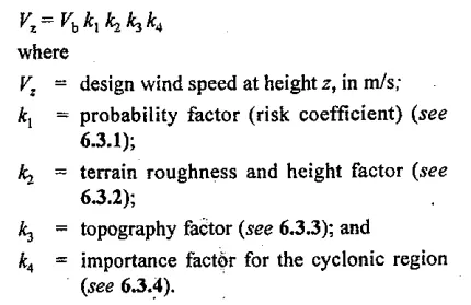
To calculate the design wind speed IS 875: Part-III given the formula in clause 6.3
Design wind speed Vz = Vb x k1 x k2 x k3 x k4
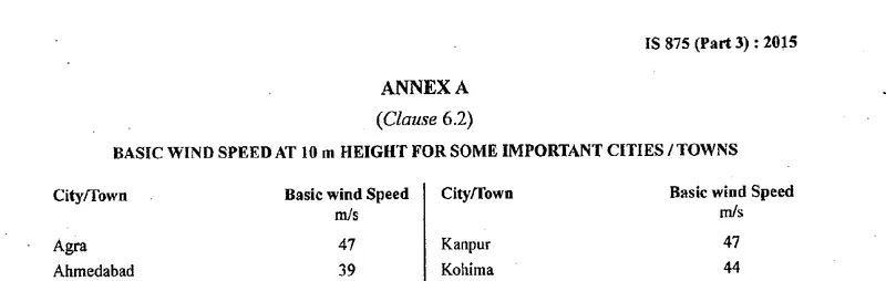
- As per given data the location of bridge is AHMEDABAD so as per IS 875: Part-III Annex - A basic wind speed Vb is given 39m/s.
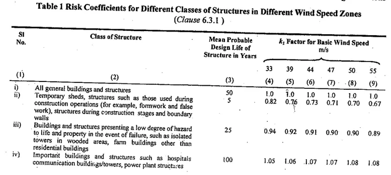
- k1 is risk coefficient as our structure is Bridge it comes into Important structure class and our basic wind speed Vb is 39m/s so k1 will be 1.06
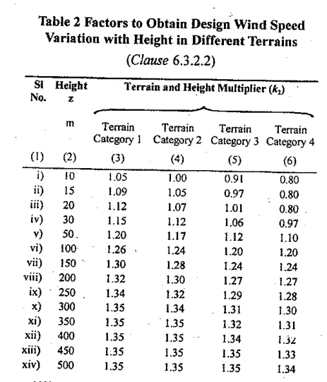
- k2 is terrain and height factor, as our structure is underground so height less than 10m so as per IS 875: Part-III it comes into category 2. So k2 will be 1.00
- k3 is the topography factor as our bridge upward wind slope is less than 3 degree and it doesn't comes into hilly areas so as per IS 875: Part-III clause 6.3.3.1 k3 will be 1.00.
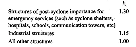
- k4 is the importance factor for cyclonic region as our bridge located in ahembdabad which doesn't comes into cyclonic region so as per IS 875: Part-III clause 6.3.4 k4 will be 1.00.
So, Design wind speed Vz = Vb x k1 x k2 x k3 x k4
= 39 x 1.06 x 1 x 1 x 1
Vz = 41.34 m/s
Now, As per IS 875: Part-III clause 7.2 design wind pressure is
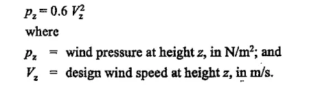
Pz = 0.6 x 41.34 x 41.34
= 1025.39 N/m2
Pz = 1.025 kN/m2
Seismic Load Calculation as per IS 1893 (PART-1): 2016
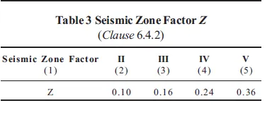
As per given data the location of bridge is AHMEDABAD so as per IS 1893 (PART-1): 2016 It comes into Zone III i.e. Z = 0.16
First we have to find out the design base shear which is Vb = Ah x W
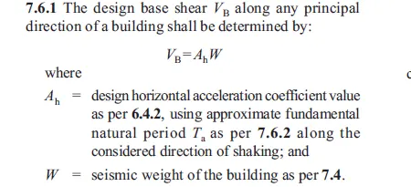
and Ah = Z/2 X Sa/g x I/R
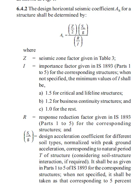
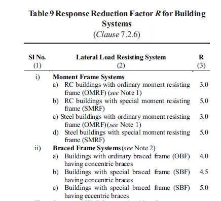
Where, Z = 0.16
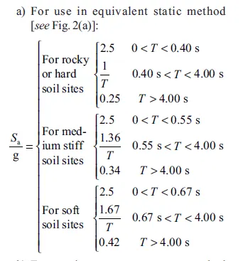
Sa/g = 2.5 for medium type of soil
I = 1.5
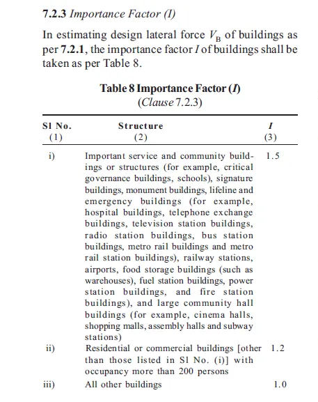
R = 5
Load Calculation On Staad Pro:
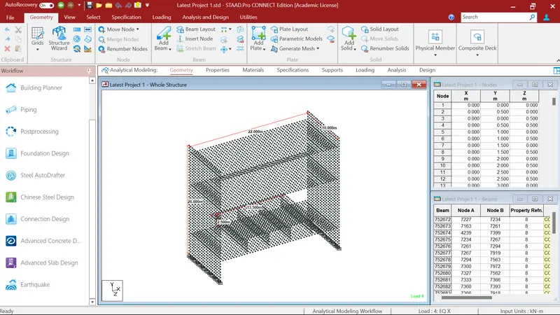
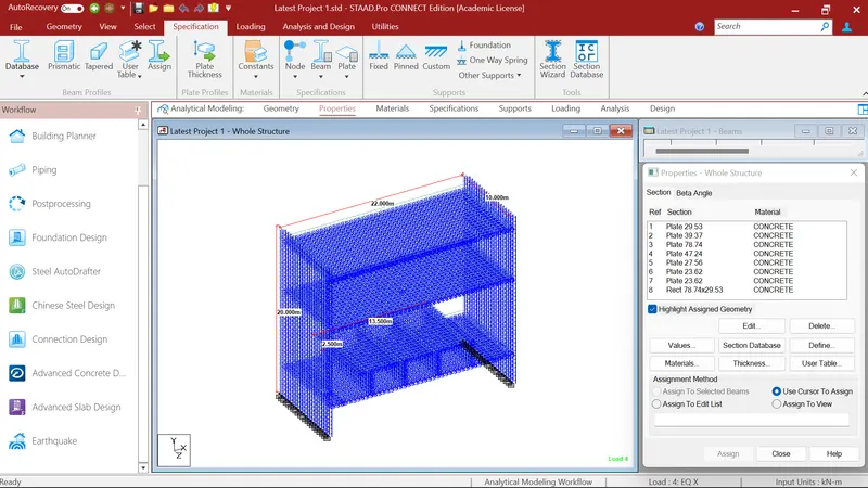
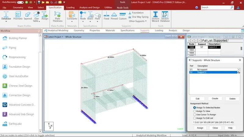
First I Created the geometry of model as per given data. Then defined the properties to the member as per given data afterthat I provide fixed support to the structure.
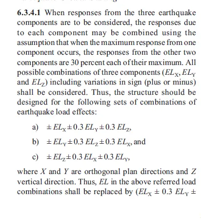
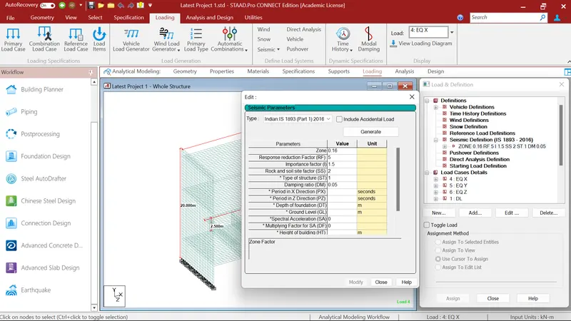
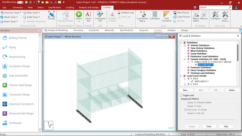
Then after I go to the loading definition where I first select seismic definition as per my structure location and details I provided Z,I,R Values. Then after I add selfweight to the structure 1 to calculate the seismic weight of the structure. Then I defined the EQ load cases in X,Y,Z direction. Then I defined seismic load combination as per IS 1893:2016 Which says that one direction to be considered maximum response and other two direction 30% of response will be considered.
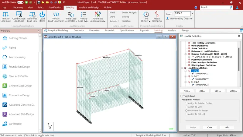
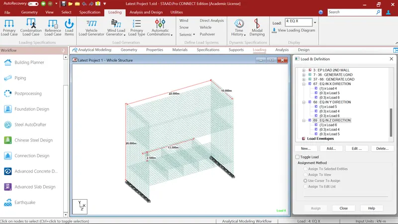
Then I defined Vehicle definition for metro train loading. I goes to the loading definitons, In loading definitions I choose Vehicle definition, Where I gave 1.8m Metro Train width then I gave laod and distance as per IRS. On platform there are two trains are moving where on one side train is moving -Z direction and another train is moving +Z direction. So I generated 30 load combination for one train and for 2nd train I generated again 30 load combinations. Then I run my train loading from the start point of bridge deck by providing x,y,z coordinates and my vehicle is moving in Z direction so I gave Z increment 0.5 for accurate results in BM & SF.
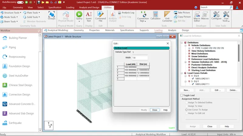
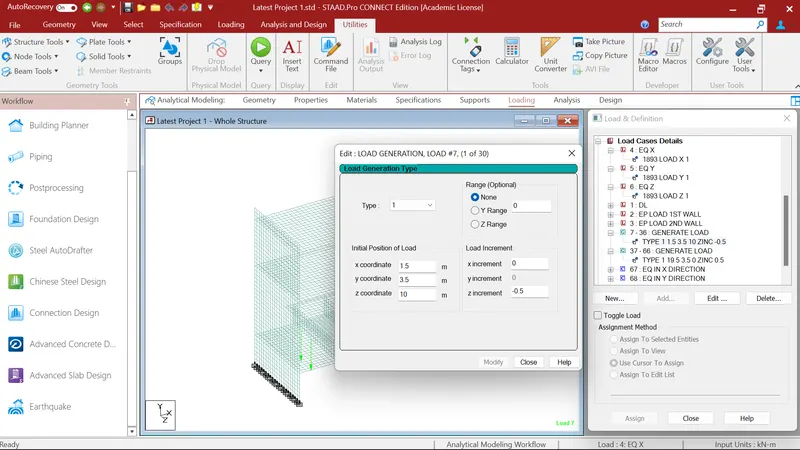
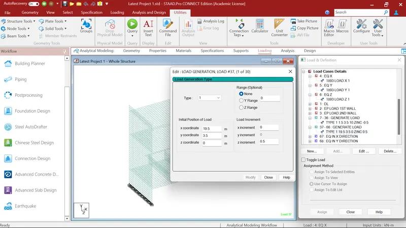
I didn't defined wind load definition because there is no requirement because structure is in underground so there will be no effect of wind loading.
Then I defined Dead load in load case details where I defined selfweight to the structure -1 in Global Y direction.
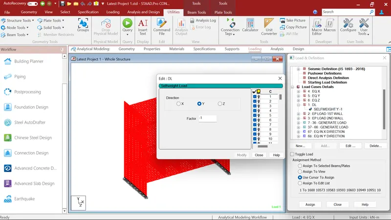
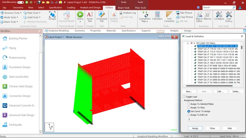
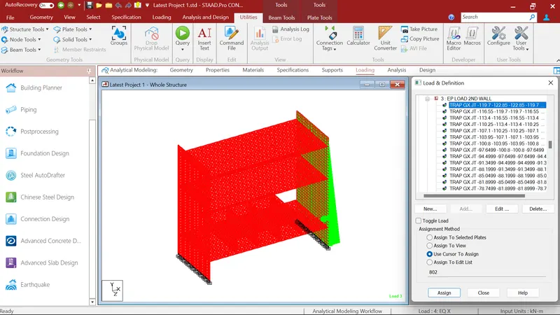
Then I defined EP load in load case details where I defined two seperate EP loads for two walls.
Active EP: In active EP, since the loaing of earth pressure is linearly varying which is maximun at the bottom and minimum at the top. I defined the Hydrostatic loading. Where Fisrt I select the active EP sides of wall. which is at 20m. After that I gave the property of W1 = 126, W2 = 0kn/m2 Interpolating along Y global axis and GX direction of pressure. After that I gave the property of W1 = -126, W2 = 0kn/m2 Interpolating along Y global axis and GX direction of pressure to the 2nd wall.
Active earth pressure = Ka x γ x h
= 0.35 x 18 x 20
Ka = 126 kN/m2
After that I gave the run analysis command and goes to the Post Processing mode.
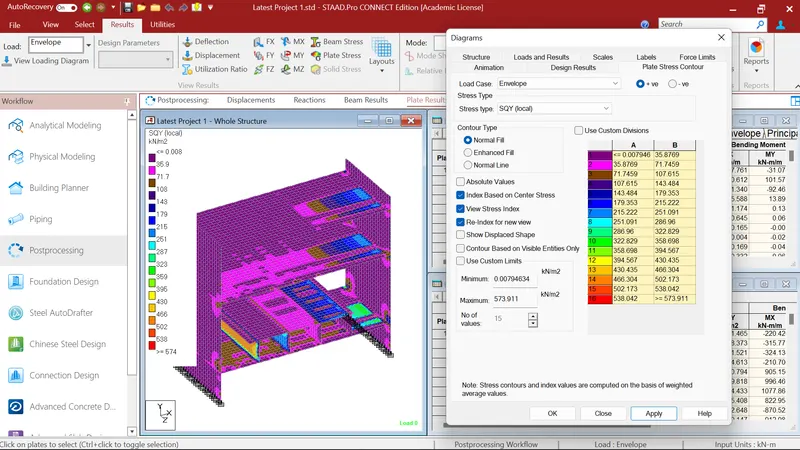
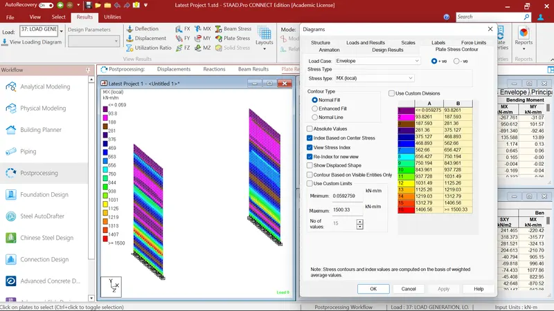
Where I first select the side walls selecting all the loads acting on structure and stress type MX i.e. bending moment in X direction. Where I got Maximum Bending moment of 1500.33 kN-m/m
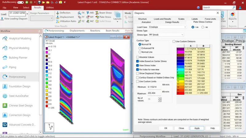
After that I choose stress type MY i.e. bending moment in Y direction. Where I got Maximum Bending moment of 255.404 kN-m/m
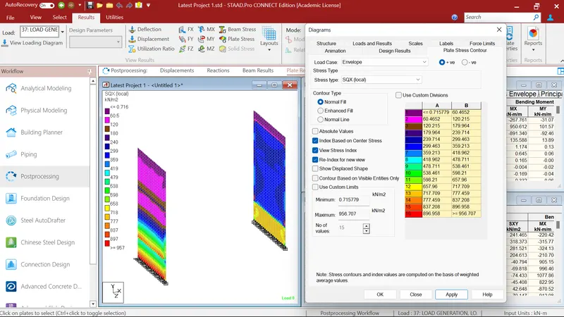
After that I choose stress type SQX i.e. maximum shear force in X direction. Where I got maximum shear force of 956.707 kN-m2
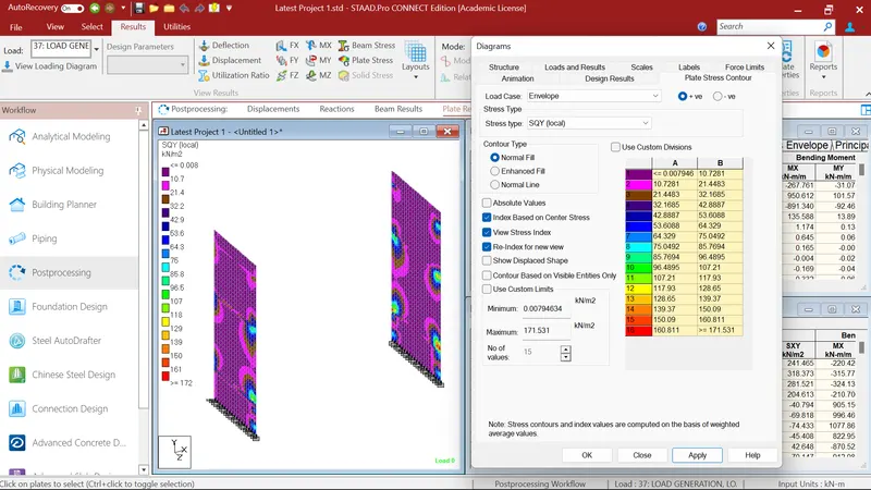
After that I choose stress type SQY i.e. maximum shear force in Y direction. Where I got maximum shear force of 171.531 kN-m2
After that I select the rectangle member of track where I go to reports, section forces where I 1st select Maximun BM In Y Direction. Where I got My = 2.916kN-m
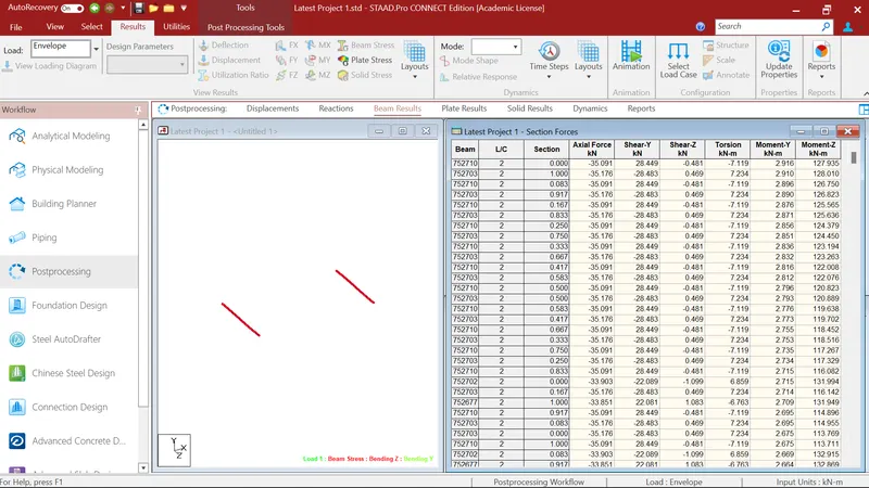
After that in section forces I select Maximun BM In Z Direction. Where I got Mz = 143.039kN-m
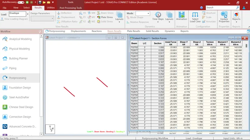
After that in section forces I select Maximun SF In Y Direction. Where I got Fy = 148.873kN
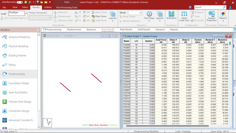
After that in section forces I select Maximun SF In Z Direction. Where I got Fz = 4.166kN
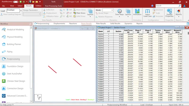
After that I select the whole structure to find out the plate stresses. Where I select all the loads acting on structure and stress type MX i.e. bending moment in X direction. Where I got Maximum Bending moment of 2139.15 kN-m/m
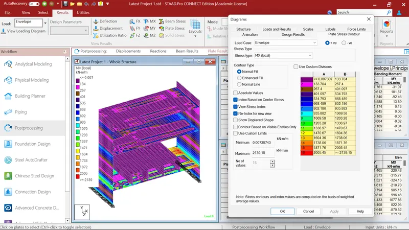
After that I choose stress type MY i.e. bending moment in Y direction. Where I got Maximum Bending moment of 2234.52 kN-m/m
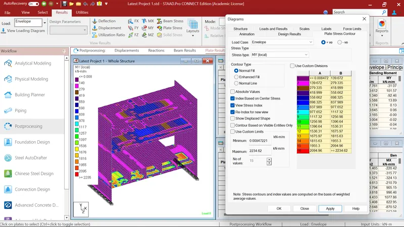
After that I choose stress type SQX i.e. maximum shear force in X direction. Where I got maximum shear force of 956.707 kN-m2
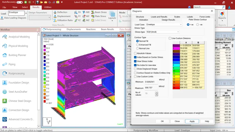
After that I choose stress type SQY i.e. maximum shear force in Y direction. Where I got maximum shear force of 573.911 kN-m2