Week 1 Challenge
Given Data:
A. Width of Bridge Deck = 10.2m
B. Span of the Bridge = 12m
C. Size of Pier = 2.5m, diameter
D. Height of Pier = 10m (Assumed)
Total width of box girder is 11.4m in which carraige way width is 8.4m, foothpath width is 1.5m each side. Top slab thickness is 0.225m, Bottom slab length is 4.020m having thickness 0.2m. Box gider having two inclined walls having length 1.975m and thickness 0.25m.
Dead Load Calculations:
1. Self weight of top slab of box girder = 8.4x0.225x25 = 47.25 kN/m
2. Self weight of foothpath = 3.0x0.225x25 = 16.875 kN/m
3. Self weight of bottom slab of box girder = 4.020x0.2x25 = 20.1 kN/m
4. Self weight of inclined wall of box girder = 2x1.975x 0.25x25 = 24.6875 kN/m
Total Dead Load = 108.9125 kN/m
Methodolgy:
Step-1: First i created a model as per given data and the dimesions are shown in the picture. As box girder cannot be modeled in Staad, so I take rectangular null beam section. And giving fixed support to the Piers.
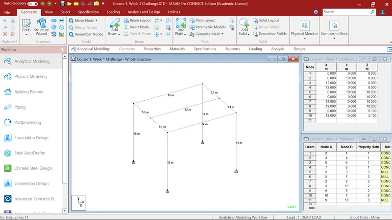
Step-2: In my 2nd step I gave pier circular concrete property having 2.5m dia, Cross beam rectangular property of 1m x 1m dimesnsion and longitudinal girder 1m x 1m propert as null beam.



Step-3: In third step I applied the self weigth to the whole structure. And applying the total self weight of box girder to the longitudinal girder of 108.913kN/m.
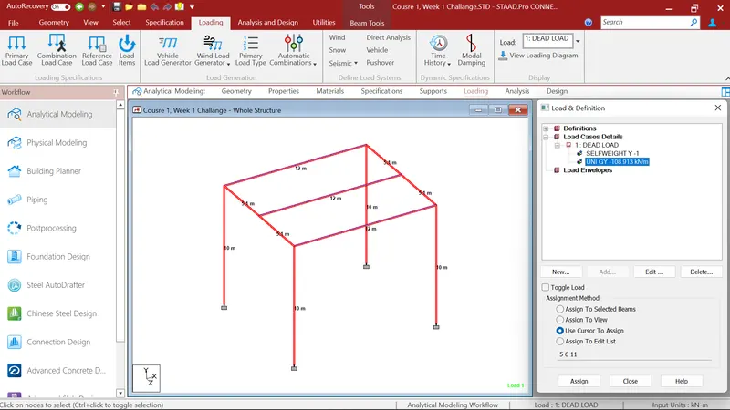
After that I gave the analysis command and run the structure to the Postprocessing menu.
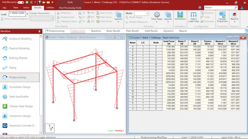
Where i firstely select the beams and checked for the Maximum Bending Moment. Where I got the maximum bending moment of 1671.345kN-m in MZ.
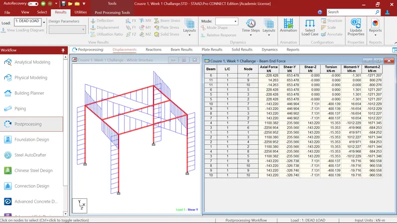
After that I again select the beams and checked for the Maximum Shear Force. Where I got the maximum Shear Force of 653.478kN in FY.
After that I checked for the Reactions.
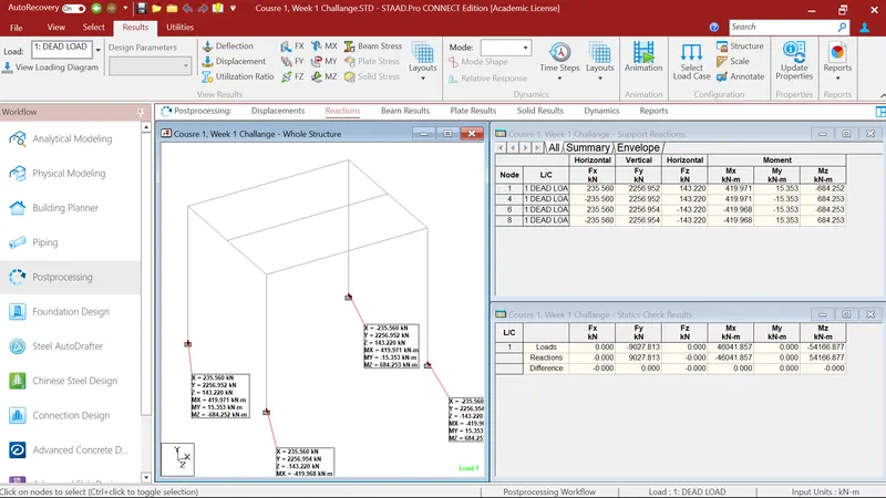
Results of Moment, Shear force and Axial force.
