Week 2 Challenge
Given Data:
1. Width of the bridge deck = 7m
2. Span of the bridge = 24m
3. Size of pier = 2m dia
4. Thickness of Deck slab = 200mm
5. Size of cross girder = 0.65 m x 1.5 m
6. Height of pier = 12m (Assumed)
There are four numbers of Longitudinal girder provided at 1.9m centre to centre distance and four numbers of cross girder at 8m centre to centre distance.
Live Load Calculation in Staad Pro.
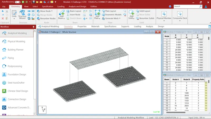
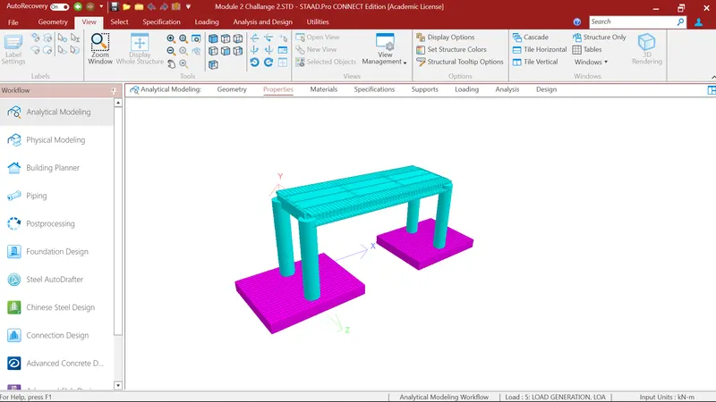
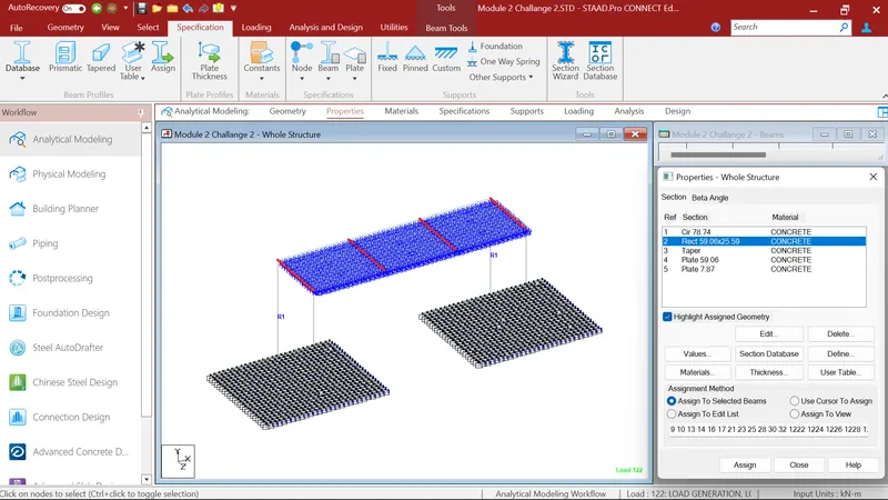
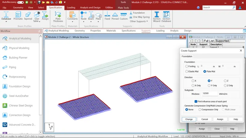
1. First I created Staad Model as per given data. In which height of pier is 12m and 2m of dia, span of bridge 24m, creating four numbers of longitudinal girders and four cross girder at 8m distance, bridge deck slab having depth of 200mm. Then I created the raft foundation of 1.5m depth. After that I created the support to foundation by giving subgrade modulus 12500kN/m2 and assigned it to the raft.
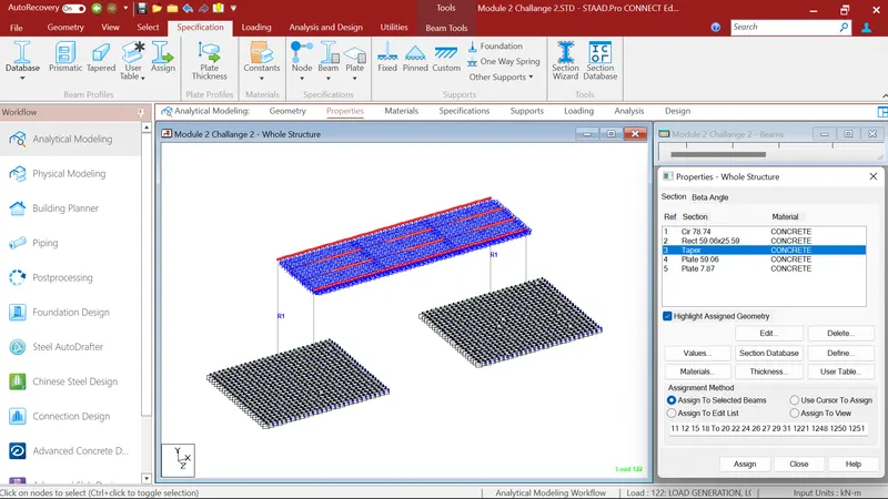
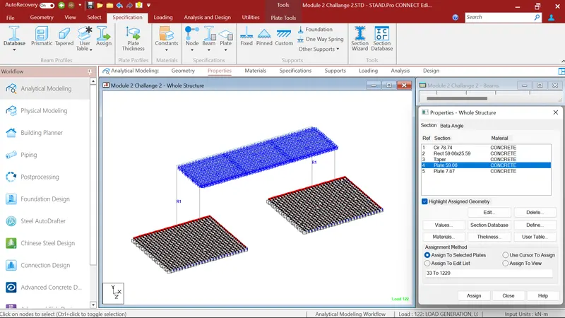
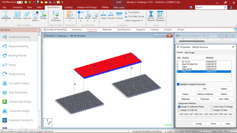
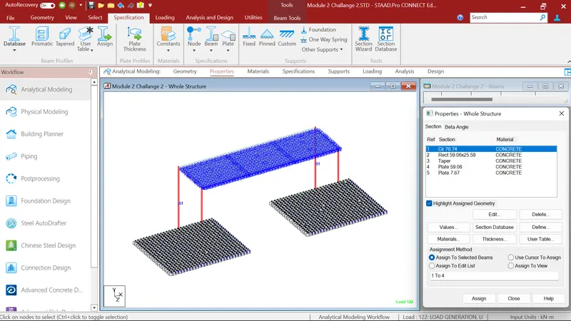
Step: 2
As per IRC Live load I gave Class 70R Wheel Loading, Class A Loading, Class B Loading.
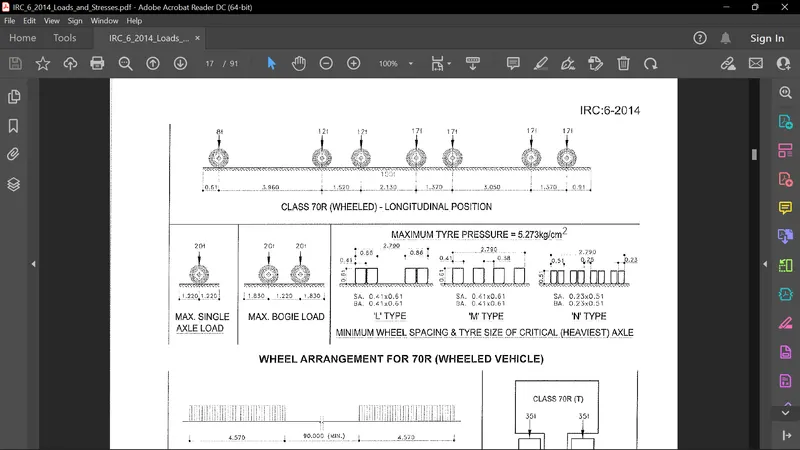
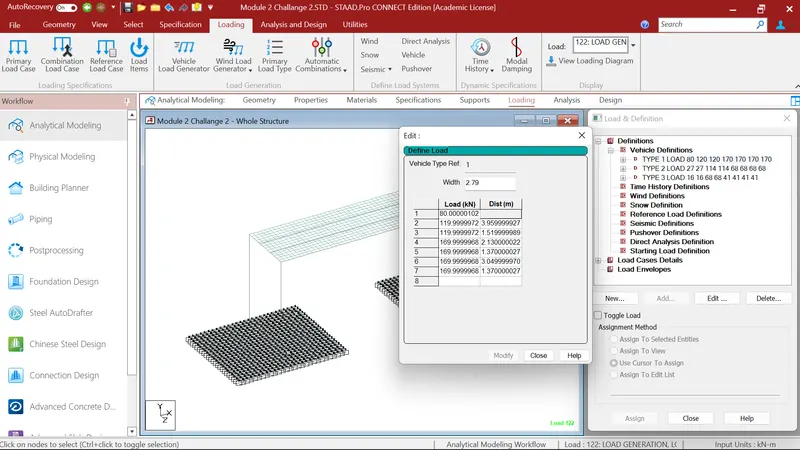
As per IRC 6-2014 IRC Class 70RW loading have total 1000kN of wheel load. In the first axle there is 80kN load at a distance of 3.960m as shown in picture and so on. Vehicle having 2.790m of width. So, in my Staad model I goes to the loading definitons, In loading definitions I choose Vehicle definition. Firstly I gave 2.79m vehicle width then I gave laod and distance as per IRC 6-2014.
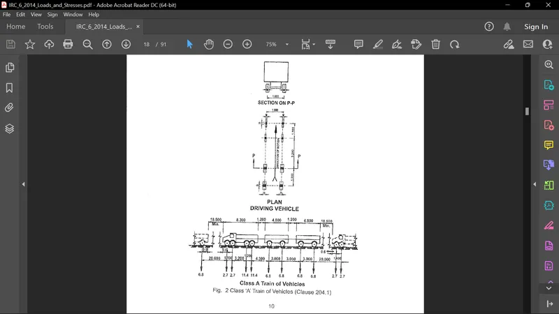
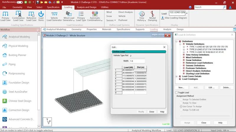
As per IRC 6-2014 IRC Class A loading have total 554kN of wheel load. In the first axle there is 27kN load at a distance of 1.1m as shown in picture and so on. Vehicle having 1.8m of width. So, in my Staad model I goes to the loading definitons, In loading definitions I choose Vehicle definition. Firstly I gave 1.8m vehicle width then I gave laod and distance as per IRC 6-2014.
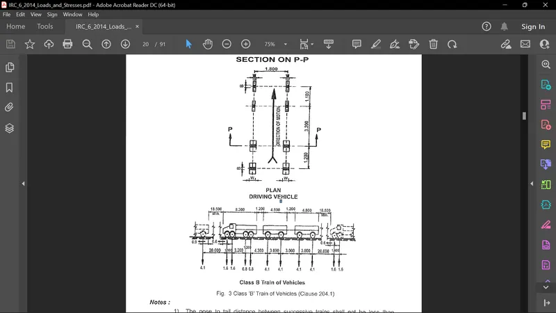
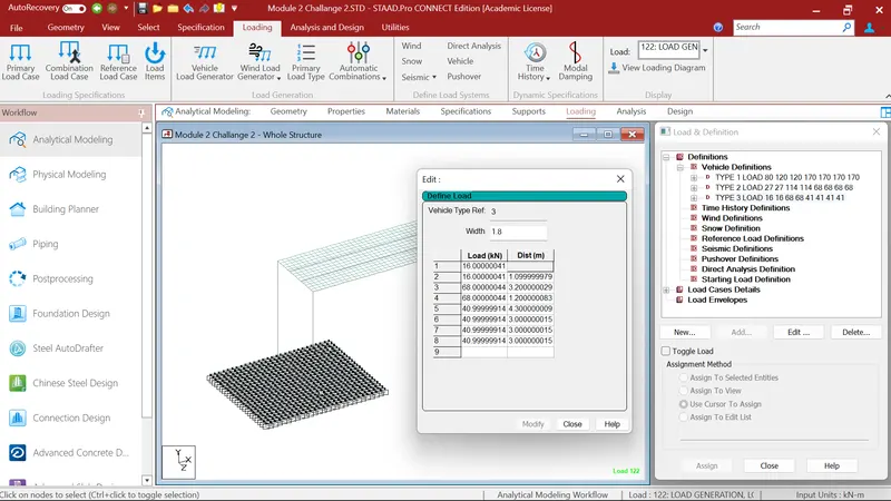
As per IRC 6-2014 IRC Class B loading have total 332kN of wheel load. In the first axle there is 16kN load at a distance of 1.1m as shown in picture and so on. Vehicle having 1.8m of width. So, in my Staad model I goes to the loading definitons, In loading definitions I choose Vehicle definition. Firstly I gave 1.8m vehicle width then I gave laod and distance as per IRC 6-2014.
Step: 3
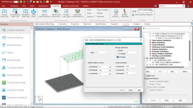
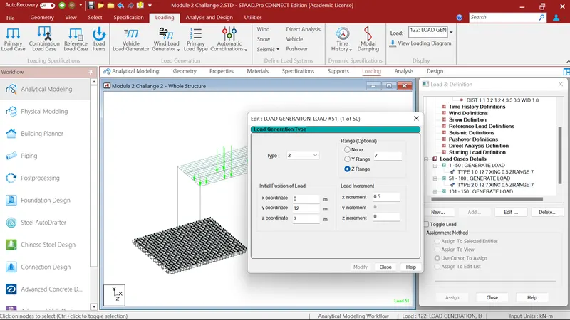
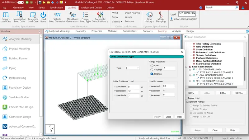
In step 3 I created load case details, where I generated 1-50 combination fo type 1 i.e. Class 70RW Loading , 51-100 combination fo type 2 i.e. Class A Loading and 101-150 combination fo type 3 i.e. Class B Loading. I choose 50 combination because of my vehicle can pass through the span of bridge completly. Then I provided Z Range of 7m because my carraigeway width of bridge is 7m. Then I run my vehicle loading from the start point of bridge deck by providing x,y,z coordinates and my vehicle is moving in x direction so I gave x increment 0.5 for accurate results in BM & SF.
Step- 4
After that I gave the analysis command and run the structure to the Postprocessing menu.
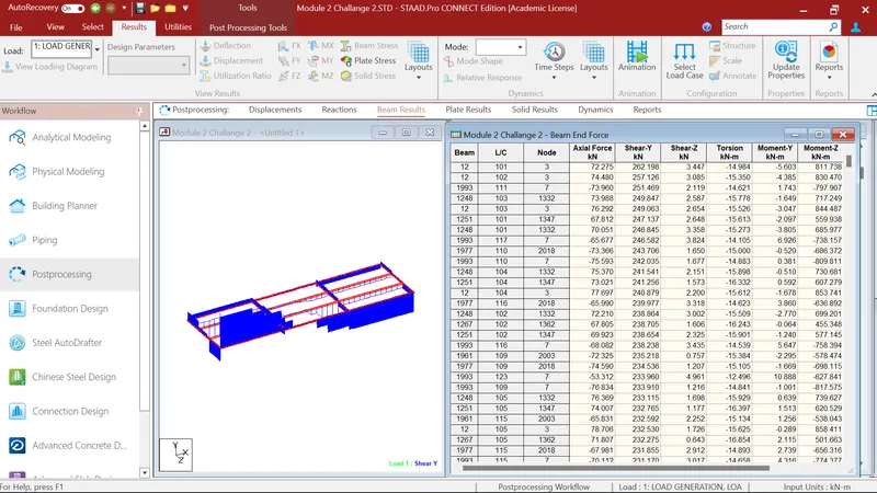
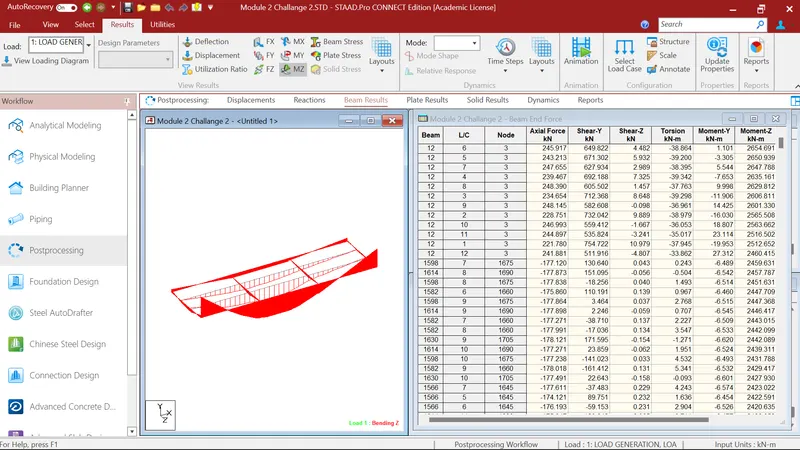
Where i firstely select the beams and checked for the Maximum Bending Moment in MZ and select 1-50 Load combinations for IRC Class 70RW Loading. Where I got the maximum bendig moment of 2654.691kN-m in MZ.
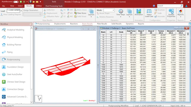
After that I again select the beams and checked for the Maximum Bending Moment in MZ and select 51-100 Load combinations for IRC Class A Loading. Where I got the maximum bendig moment of 1432.794kN-m in MZ.
After that I again select the beams and checked for the Maximum Bending Moment in MZ and select 101-150 Load combinations for IRC Class B Loading. Where I got the maximum bendig moment of 858.411kN-m in MZ.
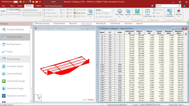
After that I again select the beams and checked for the Maximum Shear Force FY and select 1-50 Load combinations for IRC Class 70RW Loading . Where I got the maximum Shear Force of 856.290kN in FY.
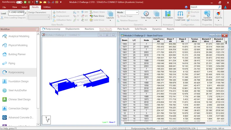
After that I again select the beams and checked for the Maximum Shear Force FY and select 51-100 Load combinations for IRC Class A Loading . Where I got the maximum Shear Force of 438.375kN in FY.
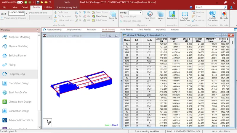
After that I again select the beams and checked for the Maximum Shear Force FY and select 101-150 Load combinations for IRC Class B Loading . Where I got the maximum Shear Force of 262.198kN in FY.