Project 1
PROJECT 1
An assemblage of electrical cables or wires that transfer signals or electrical power is referred to as a cable harness. It is also referred to as a wire harness, wiring harness, cable assembly, wiring assembly, or wiring loom. A strong substance, such as rubber, vinyl, electrical tape, conduit, a weave of extruded thread, or a mix of these, is used to bind the wires together.
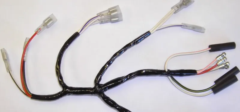
Fig. Wiring Harness
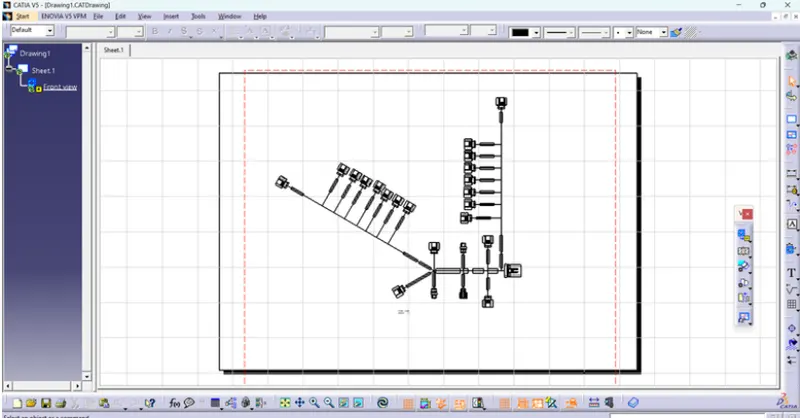
Typically, cable harnesses are created in accordance with electrical and geometric specifications. After that, a diagram for the assembly preparation and assembly is provided (either on paper or on a monitor).
First, the wires are cut to the required length, typically with the aid of specialized wire-cutting equipment. During the cutting process or on different equipment, a dedicated machine may also print on the wires. The wires are then stripped at their ends to reveal their metal (or core), which is then outfitted with any necessary terminals or connector housings. To create the cable harness, the cables are assembled and secured together on a special workbench or onto an assembly board in accordance with the design requirements. The harness is then either placed immediately in the car or shipped after any protective sleeves, conduit, or extruded yarn have been installed.
PACKAGING RULES:
- Wire harness routing must make it simple to manufacture attached equipment and wiring harnesses and to remove and maintain them.
- To reduce chaffing and handling of the wiring harness during installation, routing through minor structural holes and openings must be avoided.
- Routing must provide defense against potential harm caused by frequent abuses like being handheld and serving as temporary support for test equipment.
- When assembling or using the harness, avoid routing and clipping in the operator's blind zone.
- According to the environment and the harness's bending requirements, add more.
- Verify that the routing allows for the necessary clearance with the various adjacent parts.
- When routing close to bolted joints, avoid going over the bolts. The harness could be harmed or even pierced. Harnesses should not be near panel mounting Screws.
- If at all feasible, protect the harness when routing it close.
- The maximum distance between two clips on a straight branch is 200mm.
- Provide Clips and clamps if the harness is going to bend at multiple locations.
- The use of too many sheet-metal brackets should be avoided.
- The branch length should be more than 50 mm.
- Min distance between the clip and the branching point is to be 25 mm.
- Min distance between two branch breakouts should be 50 mm.
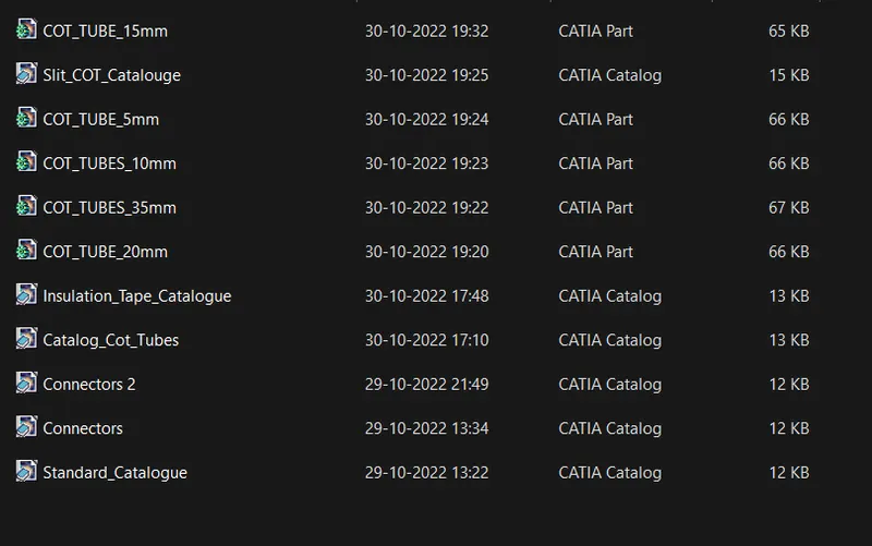
Catalog Created for protective Tubes-
Assumptions-
- Give out clips or clamps as needed.
- When constructing the wire harness, make sure there are no falling cases. To prevent cases from falling, use additional clips or clamps.
- Observe the clearance distance and keep the harness away from components that produce heat.
- To prevent puncturing the harness, avoid routing over the bolt and fastened joints.
- Avoid routing on sharp edges or else provide protection over the harness.
- Depending on the temperature outside, protection should be given as needed.
- Avoid direct support for harnesses on fuel lines routed in the engine.
- The branch length should be greater than 50mm.
- Make sure the positions you define while utilizing fake connectors are usable. For the wire harness routing, bundle sizes and other placements can be appropriately described.
- We can consider building a harness channel to be used to efficiently route and protect the wire harness if the packing area is too small and there are several packaging restrictions.
Connectors used -
1.C-173090-2
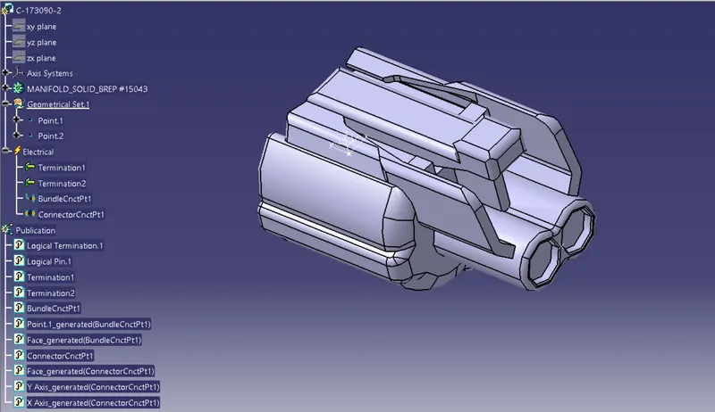
2.C-1563689-1
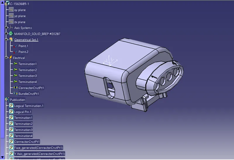
3. Inline Connector
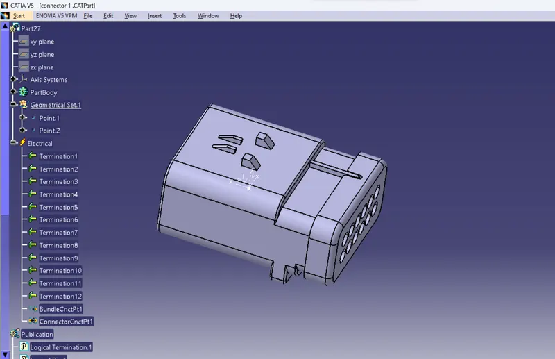
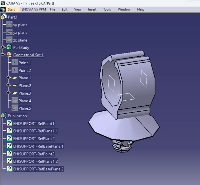
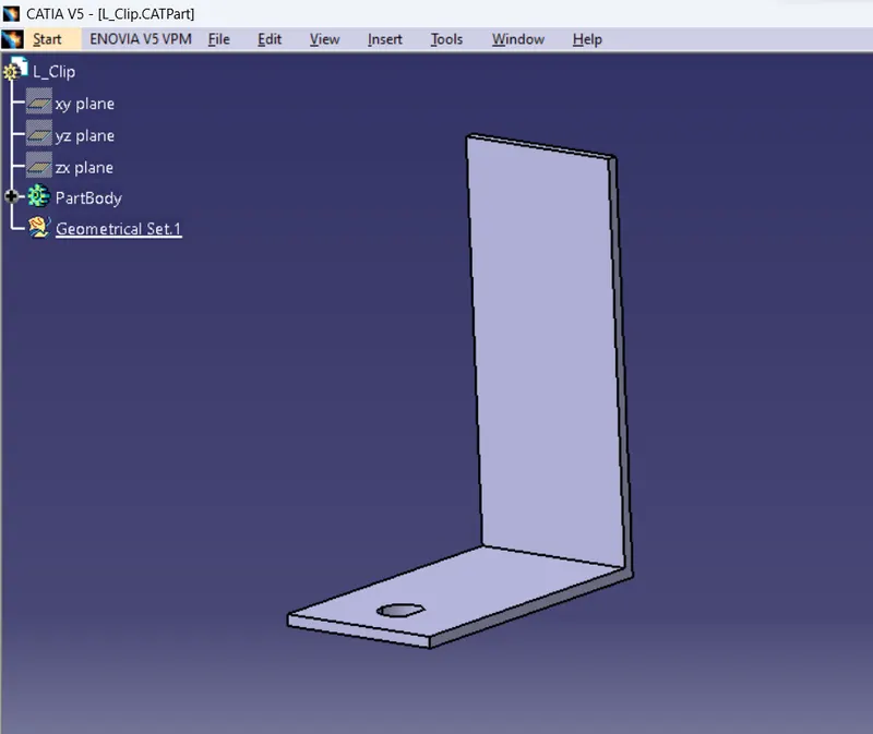
Clips Used-
1. Fir Tree Clip
2. L Clip
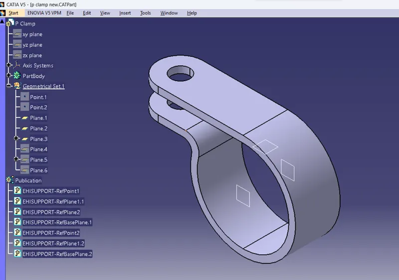
3. P Clamp
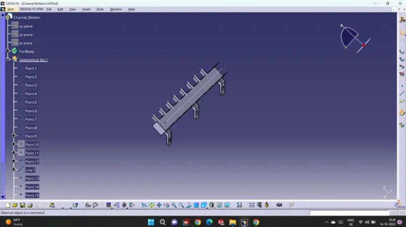
Channel Bottom Plate Used
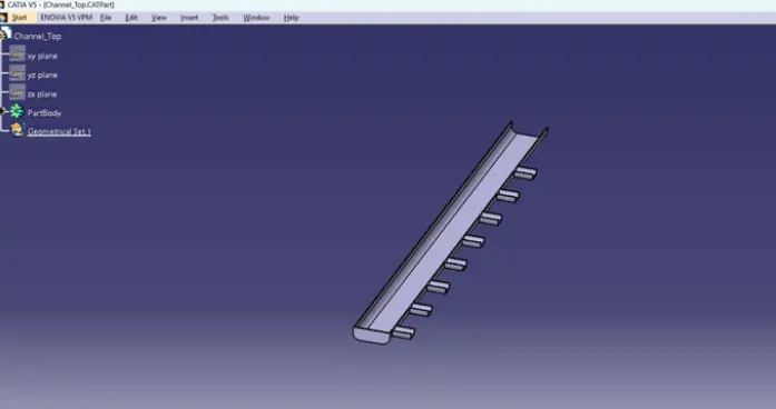
Channel Top Plate Used-
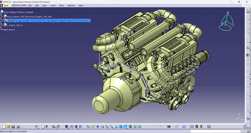
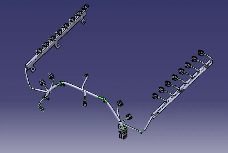
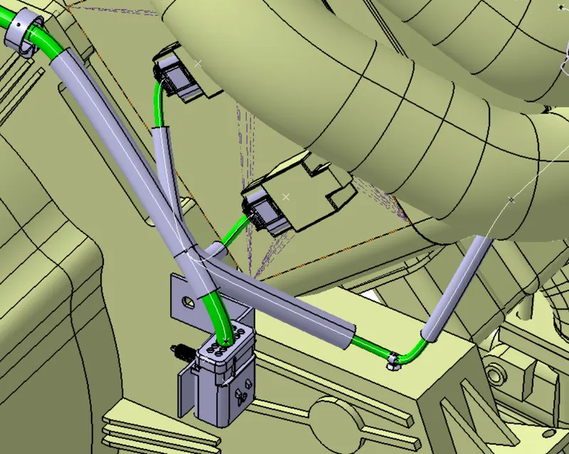
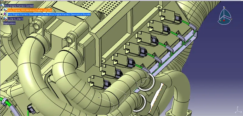
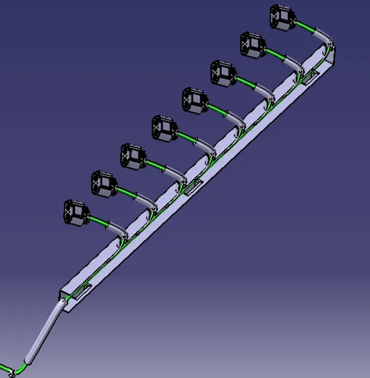
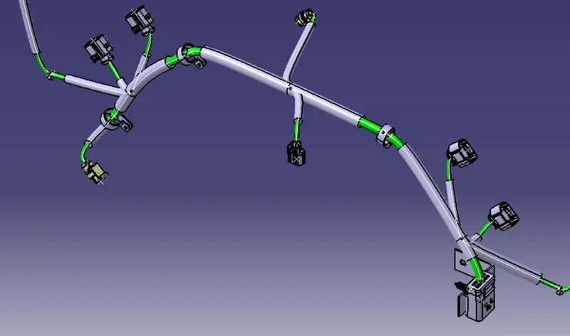
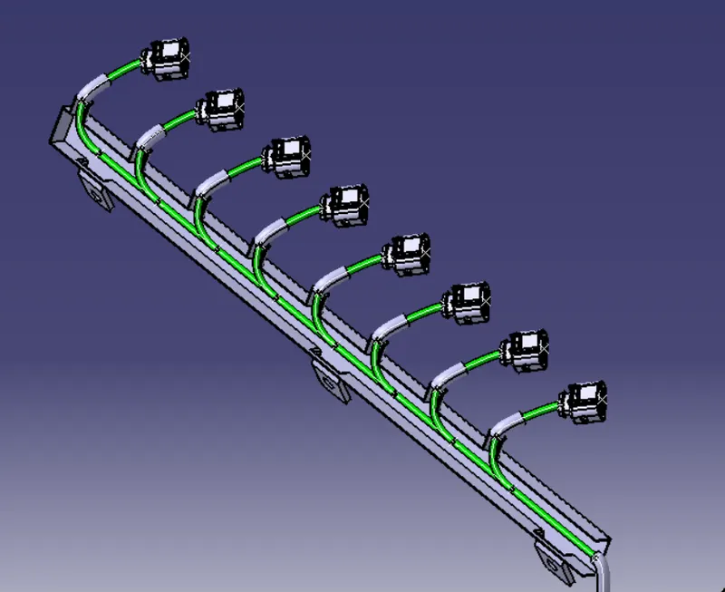
Harness Routing and Protective Coating -
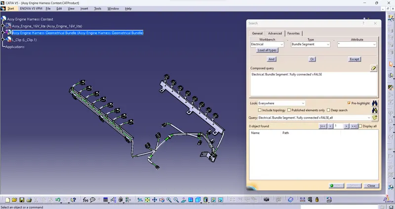
Bundle Segment Check
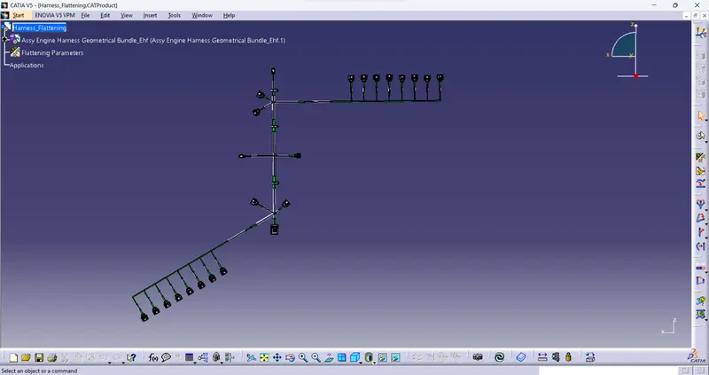
Flattening
Drafting