Project 1
PROJECT 1
DOUBLE ACTING ACTUATOR MODEL USING SIMSCAPE MULTIBODY AND SIMSCAPE COMPONENTS
OBJECTIVE:
Develop a double-acting actuator model using Simscape Multibody and Simscape components. The mechanical system of the cylinder needs to be built using Simscape Multibody library components / blocks, and the hydraulic system needs to be modelled using Simscape library physical components.
INTRODUCTION:
Double Acting Actuators:
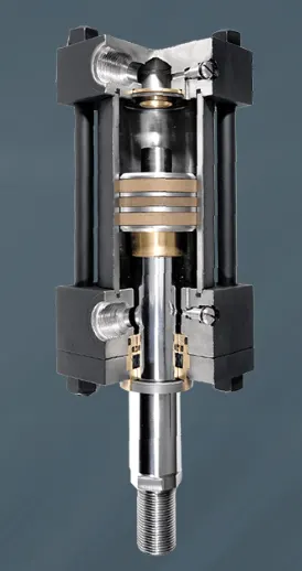
Double-acting actuators have air or liquid supplied to both sides of the piston with one side at higher pressure, which achieves the movement required to actuate the valve. This configuration uses pneumatic or hydraulic pressure of the air or liquid energy to open and close the valve.
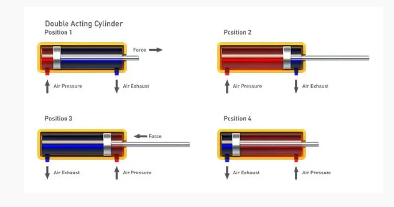
Hence the term double acting actuator. This function utilizes two air/fluid supply ports integrated into the design of the housing.
One port allows air/fluid to access the chamber between the two pistons. Supplying sufficient air/fluid pressure here will force the pistons apart and rotate the pinion in one direction. The second port allows air/fluid to access the space on the opposing faces of the pistons. Supplying air/fluid pressure here, will push the pistons together and rotate the pinion in the opposite direction.
Hydraulic Actuators:
Hydraulic actuators use liquid as a means to apply pressure to the actuator’s mechanical components. They can exert a large amount of force because liquid is not compressible but are generally limited in acceleration and speed. Hydraulic actuators are available in spring-return and double-acting designs.
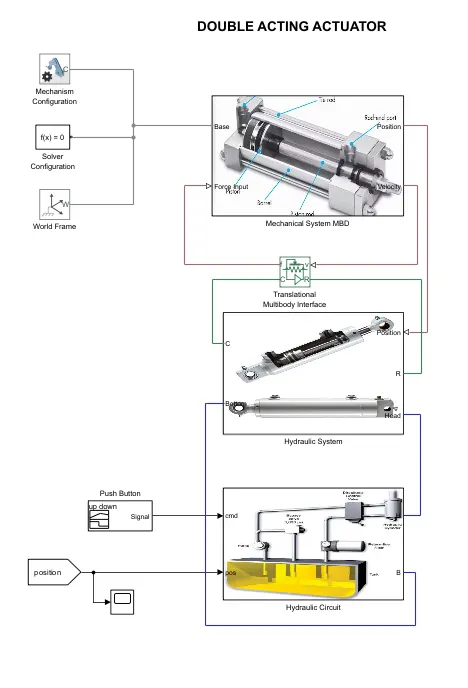
SIMULINK MODEL OF DOUBLE ACTING ACTUATOR:
MECHANICAL SYSTEM MODEL OF DOUBLE ACTING ACTUATOR:
Here, we model the mechanical system of double acting actuator which is nothing but the cylinder with piston arrangement using the Simscape multibody blocks and library components.
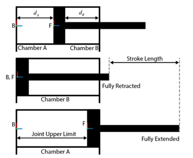
The schematics show the cylinder in three configurations: half-retracted, fully retracted, and fully extended.
Cylinder Parameters and calculation:
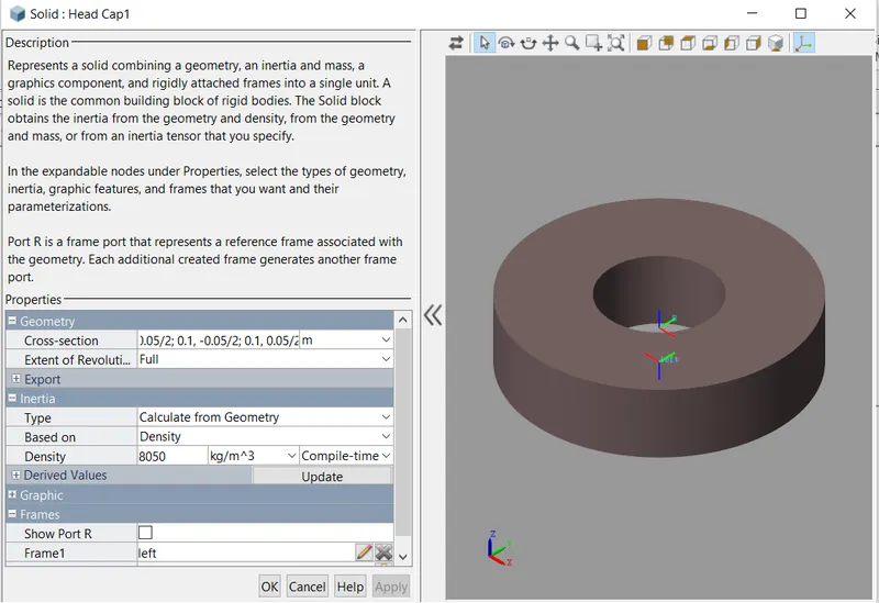
Head Cap Dimensions: Inner Radius - 0.04m,Outer Radius - 0.1m and Length-0.05m
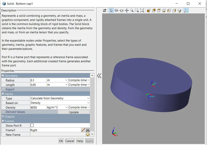
Bottom Cap Dimensions: Radius-0.1m,Length - 0.05m
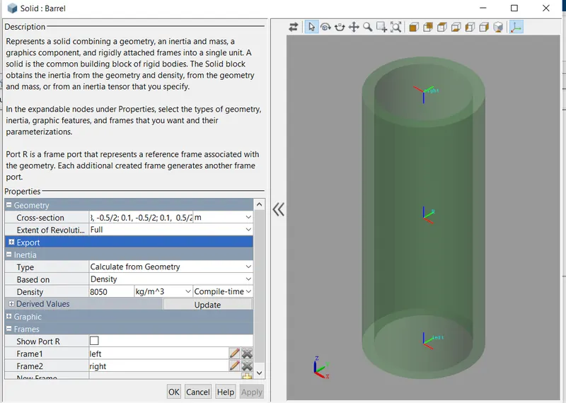
Cylinder Barrel Dimensions: Inner Radius - 0.08m,Outer Radius - 0.1m and Length-0.5m
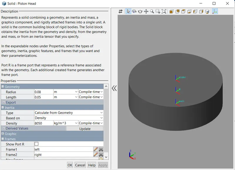
Pistion head Dimension: Radius-0.08m,Length - 0.05m
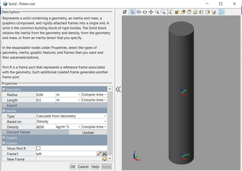
Piston rod Dimension: Radius-0.04m,Length - 0.5m
Chamber A piston Area: pi*0.08^2 m^2
Chamber B piston Area: pi*(0.08^2-0.04^2) m^2
Dead Volume: 1e-4 m^3
Stroke Length - 0.45m
Chamber A length dA = 0.225m
Chamber B length dB= stroke length - dA = 0.45-0.225 = 0.225m
Simscape Multibody Library blocks used:
Solid - cylindrical
Solid - revolve
Prismatic Joint
Mechanism configuration
world frame
The above blocks are used to model the mechanical system of the double acting actator.
MECHANICAL SYSTEM:
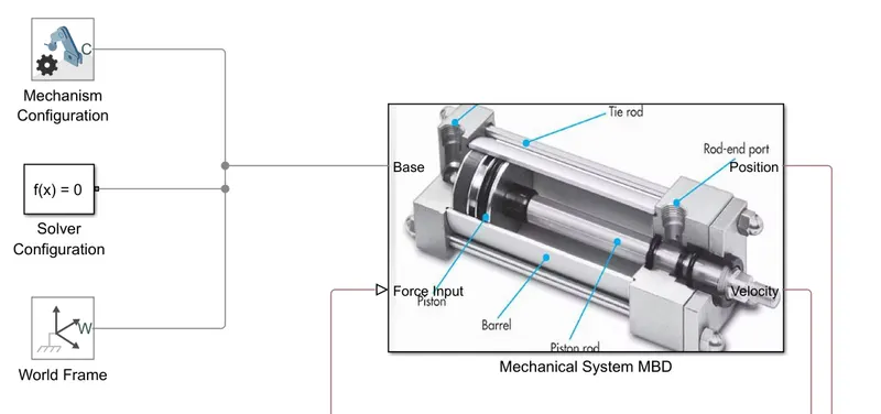
Here, the basic blocks for simscape multibody mechanism configuration,solver configuration and world frame is added.
Mechanical subsystem:
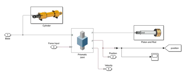
In mechanical subsystem, model is build using the MBD blocks, cylinder blocks like head,bottom caps and barrel is modeled and piston and rod is model and both is connected with the prismatic joint.
Here, we use the Revolved Solid (Simscape Multibody) and Cylindrical Solid (Simscape Multibody) blocks to model the cylinder and piston
To provide the translational degree of freedom for the piston, use a Prismatic Joint (Simscape Multibody) block. To easily calculate the lengths of the chambers A and B, you can attach the base frame (B) and follower frame (F) of the joint to the centers of the left inner surface of the chamber A and the left surface of the piston, respectively. Make sure that the Z-axes of the B and F frames are aligned and both point toward chamber B.
Using this convention, the length of the chamber A, dA, is the position output of the joint block, and the length of the chamber B, dB, equals the difference of the stroke length and dA. To ensure that the piston does not travel beyond the ends of the cylinder, you can specify the upper and lower position limits of the Prismatic Joint block.
Cylinder Assy:
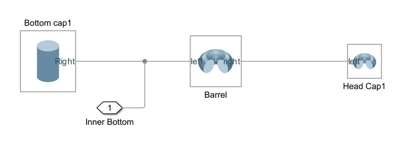
The solid blocks are used here, radius ,length and cross section area is given in the geometry of the solid blocks and the frames are selected on z axis and left right frames are carefully designed.
Bottom Cap:
Barrel:
Head Cap:
Piston Assy:
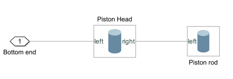
Piston head and rod are modeled using the solid blocks and corresponding frames are defined.
Piston Head:
Piston Rod:
Prismatic Joint:
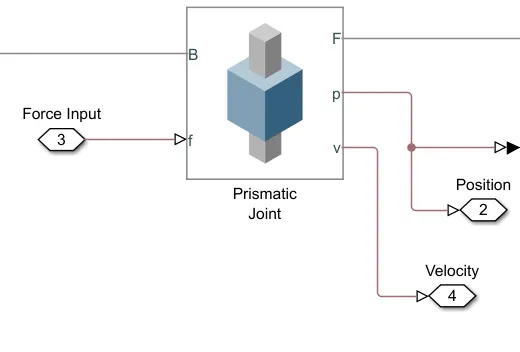
To provide the translational degree of freedom for the piston, use a Prismatic Joint (Simscape Multibody) block.
To limit the travel of the piston:
-
In the Prismatic Joint block, under the Limits section, select the Specify Lower Limit and Specify Upper Limit parameters.
-
Under the Specify Lower Limit section, the Bound parameter indicates the minimum distance between the frames B and F of the joint block. In this example, specify the Bound parameter as 0 m.
-
Under Specify Upper Limit, the Bound parameter indicates the maximum distance between frames B and F of the Prismatic Joint block. In this example, specify the Bound parameter as the stroke length of the cylinder. stroke length = 0.45m.
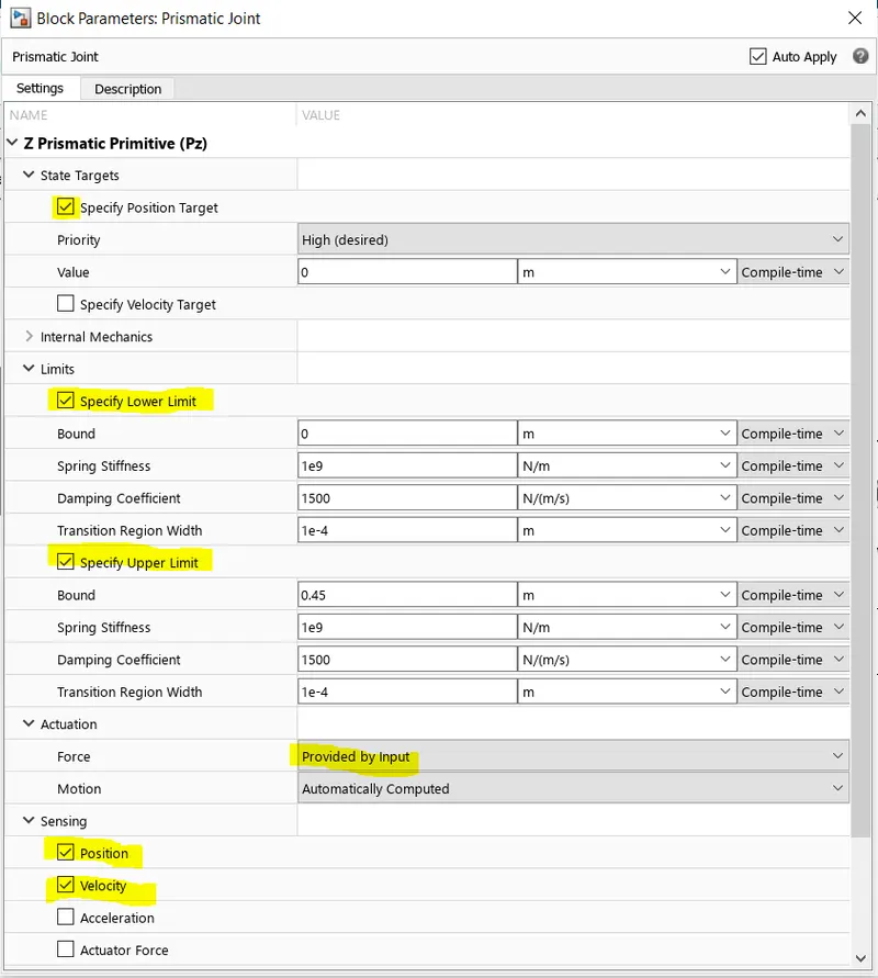
In actuation,provided by input is selected and position and velocity of the system is sensed and other parameters like spring stiffness,damping coefficient are given.
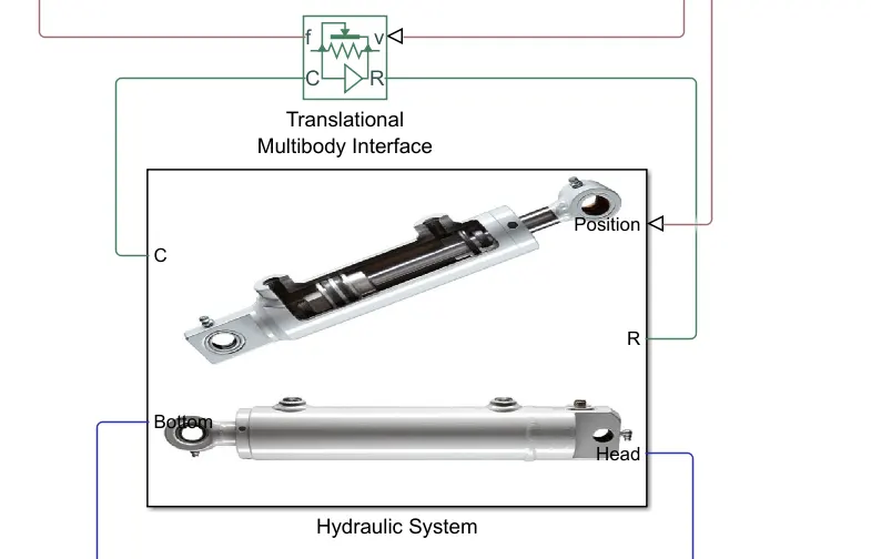
Translational Multibody Interface:
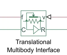
This block is an interface between a Simscape Multibody joint and a Simscape mechanical translational network. Ports R and C are mechanical translational conserving ports that connect to the two nodes in the mechanical translational network which share the same force and relative velocity as a primitive in the Multibody joint. Ports v and f are physical signal ports that connect to the Multibody joint. Input port v accepts the relative velocity sensing output from the joint primitive. Output port f provides the force actuation input to the joint primitive.
Translational Multibody Interface block connects the Translational Mechanical Converter (IL) blocks to the Prismatic Joint block.
Hydraulic chamber Subsystem:
chamber A and chamber B:
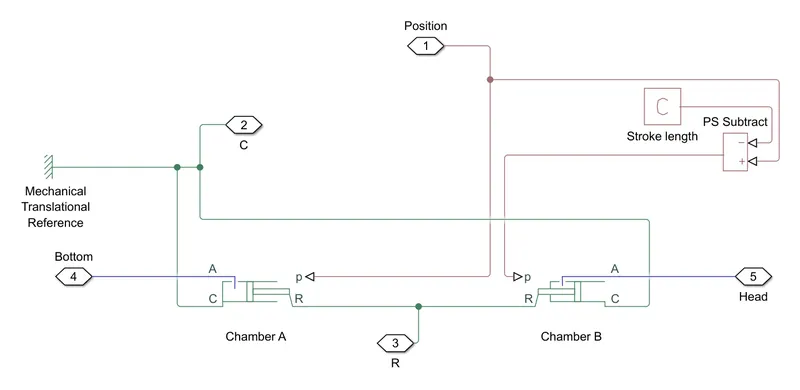
Here, Two Translational Mechanical Converter (IL) blocks to model the chambers A and B of the cylinder. A Translational Multibody Interface block connects the Translational Mechanical Converter (IL) blocks to the Prismatic Joint block
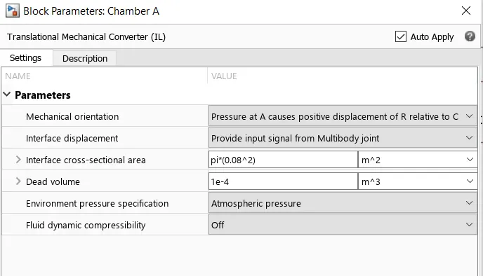
In chamber A, a pressure at port A moves the piston from 0 to stroke length. The displacement of the piston equals to the position output of the Prismatic Joint block. To model chamber A:
-
Connect the ports C and R of the Translational Multibody Interface block to the ports C and R of the upper Translational Mechanical Converter (IL) block, respectively.
-
In the Translational Mechanical Converter (IL) block, set Interface displacement to
Provide input signal from Multibody jointto enable port p. -
Connect ports p of the Prismatic Joint block and Translational Mechanical Converter (IL) block.
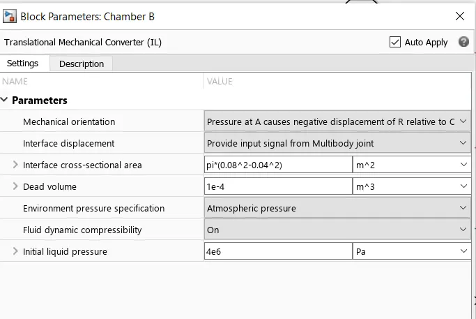
In chamber B, the pressure at port A moves the piston from 0 to negative stroke length. Therefore, you need to change the default orientation and add an offset to the input position signal of the lower Translational Mechanical Converter (IL) block. The offset equals -dB.
-
In the lower Translational Mechanical Converter (IL) block, set Mechanical orientation to
Pressure at A causes negative displacement of R relative to C. -
Set Interface displacement to
Provide input signal from Multibody jointto enable the port p. -
Add a PS Constant block and specify the constant as the stroke length of the cylinder.
-
Add a PS Subtract block, then connect it to the PS Constant and Prismatic Joint blocks as shown in the diagram. Note that the output of the PS Subtract block equals -dB.
Chamber A:
Here,chamber A is for positive displacement of the piston
Chamber B:
Here,chamber B is for negative displacement of the piston
.
HYDRAULIC CIRCUIT:
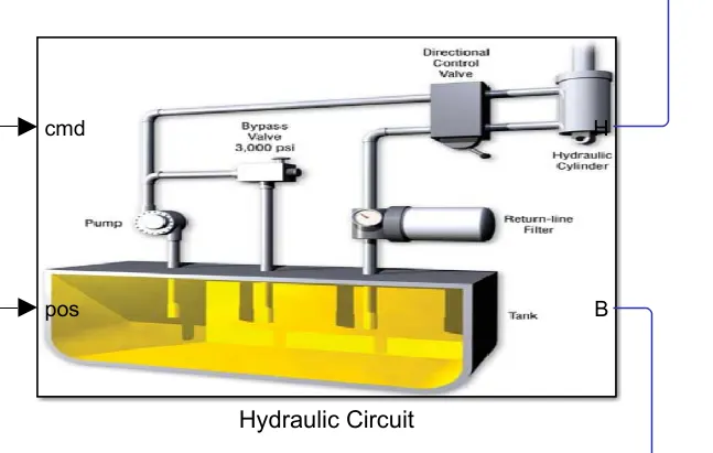
Hydrulic circuit consist of the valve controller, valve with orifices and the source of hydraulics.
Hydraulic circuit subsystem:

Here, we have the source system, valve controller and valve mechanism subsystems.
Source System:
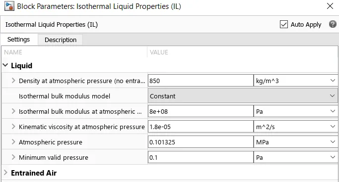
Isothermal Liquid properties:
The below properties of the isothermal liquids are choosen.
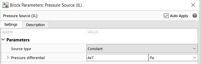
Pressure source:
This block represents an ideal mechanical energy source in an isothermal liquid network that can maintain a constant or controlled pressure differential regardless of the flow rate. The source does not generate any losses due to friction.
Reservoir:
This block sets a constant or controlled boundary condition in an isothermal liquid network. The volume of liquid inside the reservoir is assumed infinite. Therefore, the flow is assumed quasi-steady. Liquid leaves and enters the reservoir at the reservoir pressure.
Valve :
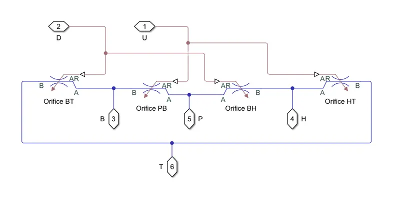
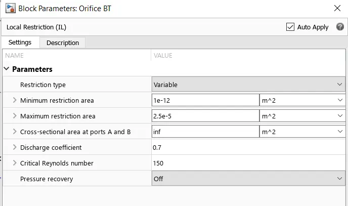
The 4 orifices are selected,One for fluid input from pump P,fluid exhaust to the tank T,port for Bottom of the cylinder B,port for head of the cylinder H.
The orifice with the below properties and min and max restriction area is selected.
Valve control:
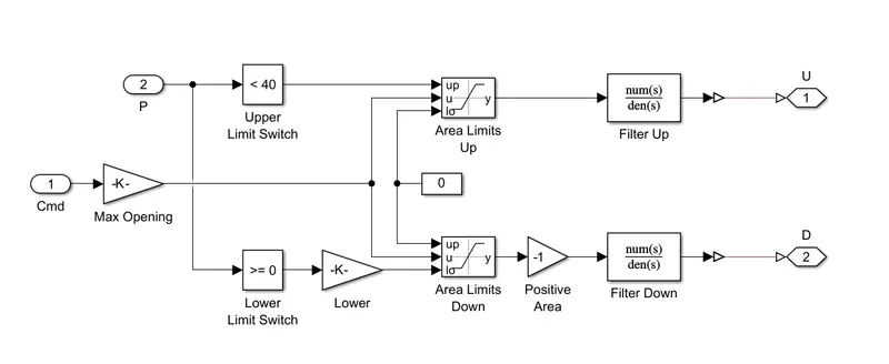
The valve control get the position feedback and input command open the orifices accordingly to make the piston movement inside the cylinder barrel.
It uses the transfer function based controller to control the valve dynamics.
Input and Feedback:
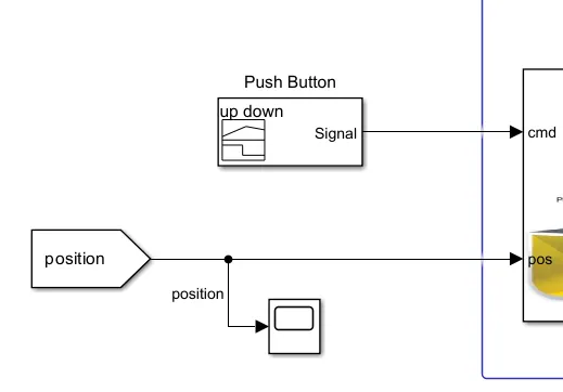
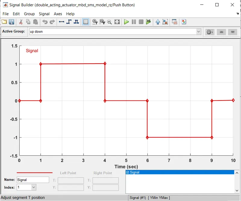
The signal builder block is used for the input and the position is feedback to the valve controller.
Signal builder block:
Results:
The simulation is run for 10 secs,based on the input given.
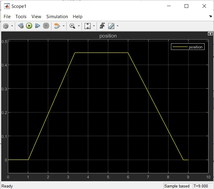
Here,the scope result of position shows that at 1 sec the piston is moving at positive direction at 4th sec it goes to bottom dead center and at 6th sec the piston have negative displacement and move to the top dead center of the cylinder and at 9th sec it comes to rest.
The ramping line in the output shows the piston movement for positive and negative displacement for the given signal +1 and -1.
Mechanics Explorer Results:
The mechanics explorer shows the Multibody dynamics model of the double acting actuator simulation of piston moving inside the barrel.
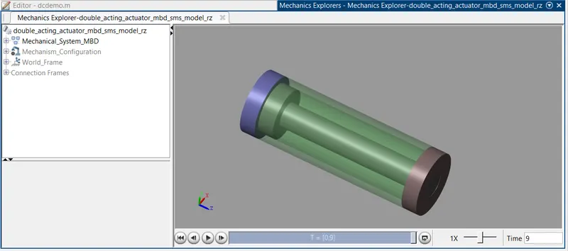
The video animation of the simulation is given below:
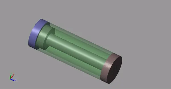
It clearly shows the double acting actuator working with cylinder and piston according to the step input given to the model with the help of isothermal liquid properties and parameters and with the help of valves and valve controls.
Conclusion:
The Double acting actuator model is developed using the simscape multibody and simscape components and the Mechanical system of the cylinder is builded using the simscape multibody library components and blocks.
The hydraulic system of the double acting actuator is modeled using the simscape library physical components.
The position of the actuator piston according to the given input commands are observed using the scope and mechanics explorer.
References:
https://in.mathworks.com/help/simscape/ug/modeling-a-double-acting-actuator.html
https://instrumentationtools.com/single-acting-vs-double-acting-actuators/
https://valveman.com/blog/what-does-a-double-acting-actuator-do/
Thank you
Submitted By
B.Riyaz
04/11/2022