Project 1
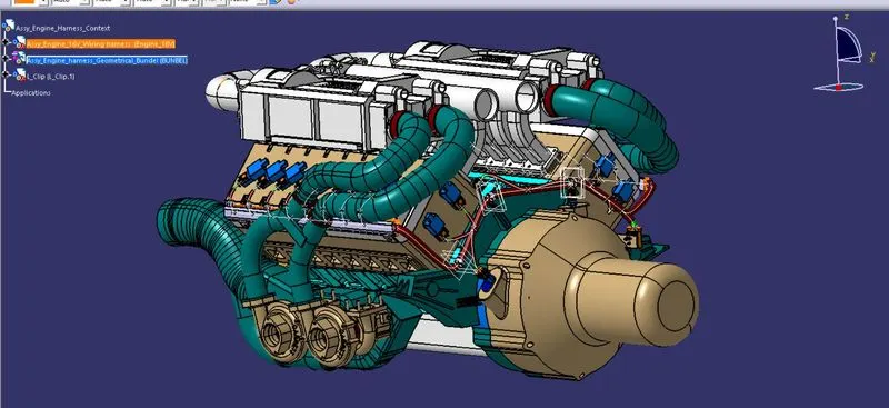
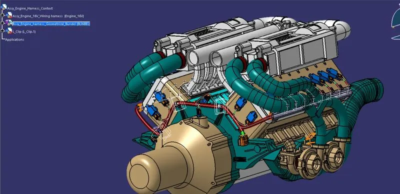
Route the Wiring harness on the Given Engine and Prepare to flatten view drawing in CATIA V5. Application of all Packaging rules, Industry best practices studied in this course shall be demonstrated in design. Apply Protection coverings as required.
Available connector 3D data can be used, or you can download the connectors from www.te.com
Prepare & Submit all necessary reports like clearance, Clipping/Clamping selection, Harness fixing requirements, Harness continuity, and Assumptions if any along with CATIA 3D data.
Engine Wire Harness Routing in CATIA V5
Aim-
To route the wiring harness on the given Engine and flatten the view drawing in CATIA V5.
Objective:
The objective of the project is to route the wiring harness on the given V16 Engine used in the Volvo bus and prepare to flatten the view drawing in CATIA V5. All types of packaging rules have to be followed while routing the harness in the engine. Also, Industry best practices should be demonstrated in design. All the necessary details like clearance, clipping/clamping selection, harness fixing requirements, harness continuity should be provided in order to design the wiring harness.
Introduction:
An engine wiring harness is an organized set of wires, cables, connectors, and terminals that controls a vehicle’s electrical system. Engine wire harnesses relay electrical power and control information to outlying components such as Alternators, Audio Systems, Batteries, Blower Motors, Computers, Fuel Injectors, Fuses, Windshield Wipers, and everything else that is controlled electrically that can be found in a vehicle.
ENGINE CAD PART
Engine cad-part is shown below in two different angles for better understanding.
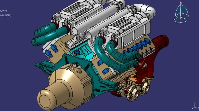
all the connectors and sensor for shown in blue for better visual
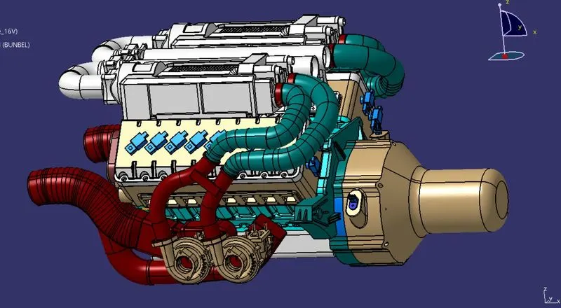
- The above figure shows the 16-valve Volvo Engine which has 16 cylinders 8 cylinders are placed on the right side and 8 cylinders are placed on the left side.
- There is a total of 16 injectors where 8 injectors are used for 8 cylinders on the right side and 8 injectors are used for another 8 cylinders on the left side.
- Also, there are 4 cam-shaft sensors, are placed and shown in the image below.
- so there is a total of 20 sensors that we have used to connect electrically.
- Generally, 4-pole connectors are used for fuel injectors of the engine.
- in this model 3-pole and 2-pole connectors are also used for oil temperature sensors and gear indicators.
- 12-pole connector is mounted on to of the metal clap to connect with ECU
- Total 23 numbers of connector is used in this engine wiring harness.
- the metal channel is used to bring the wiring harness to protect the wire from direct contact with heat.
CONNECTOR
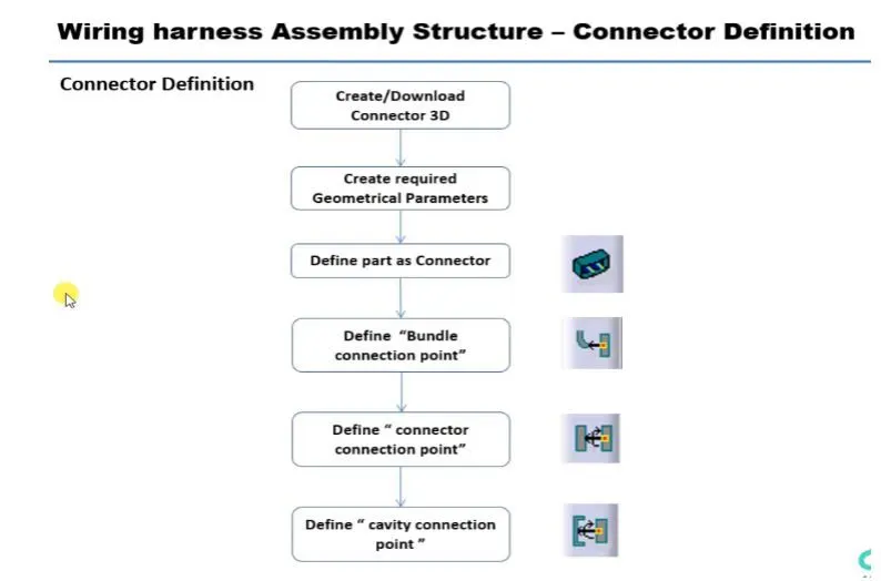
CONNECTOR DEFINITIONS IN SHOW ABOVE CATIA V5
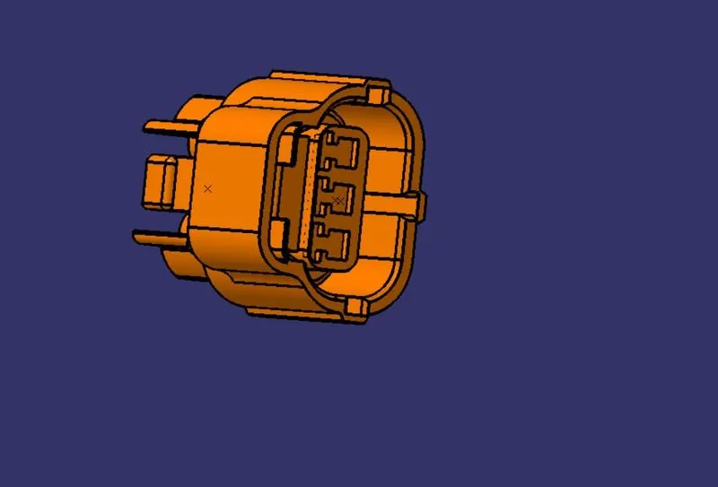
4-POLE CONNECTOR
CODE: C-1563689-1.2
CONNECTOR USED: 20
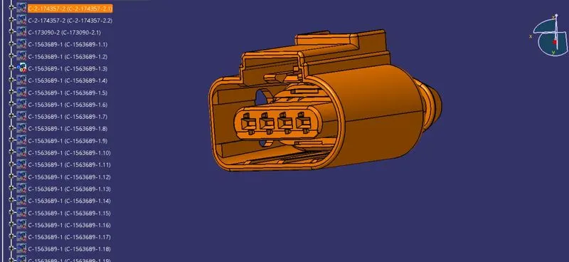
3-POLE CONNECTOR
CODE : C-2-174357-2.1
CONNECTOR USED : 1
2-POLE CONNECTOR
CODE: C-173090-2.1
CONNECTOR USED: 1
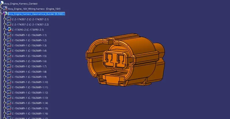
A TOTAL 23 NUMBER OF CONNECTOR IS USED IN THE ENGINE WIRING HARNESS
In this step, we are placing connectors to fuel injector sensors and cam-shaft sensors. So we will require total 20 connectors which have to be added in the Engine Harness Geometrical Bundle Assembly. We have to use manipulation tools along with a compass, snap, and smart move features to locate all the 20 connectors at their desired locations.
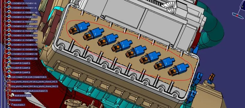
Left side 8 (4-pole) connectors are marked and shown above.
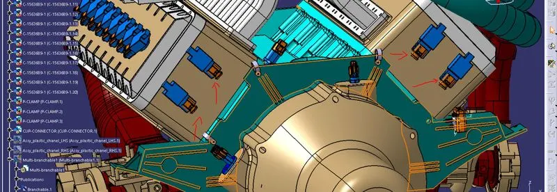
in the above image, we can 4 (4-pole) connectors used for the can sensor those sensors are highlighted with red arrows.
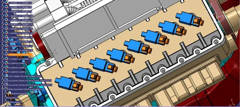
The right side 8(4-pole) connector is shown it connect with injector connectors.
Now, we have to add a sheet metal brackets in order to provide mounting for the interconnection connector. Also, we have to make sure that the bracket is placed inside the context assembly and outside of the engine and geometrical bundle assembly. The bracket should be mounted on the existing bolt as shown below. This bracket should have locking system in a clockwise direction so that it can't be moved freely. In herein below figure, a rib is performing the locking feature for the bracket. All the design ideas should be discussed with the engine designing team so that there won't be any disturbance to the smooth working of the engine in real-world applications.
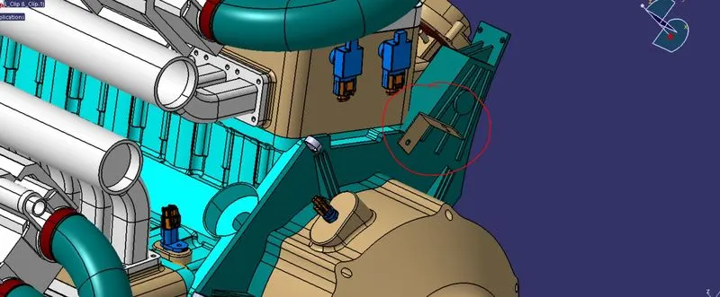
Here, a 12 pole connector "C-776438-4" and mounting cavity "C-1924487-2" is together used as an interconnection connector. The required cad data is downloaded from te.com. First, we have to define 12 pole connector and mounting cavity electrically as below.
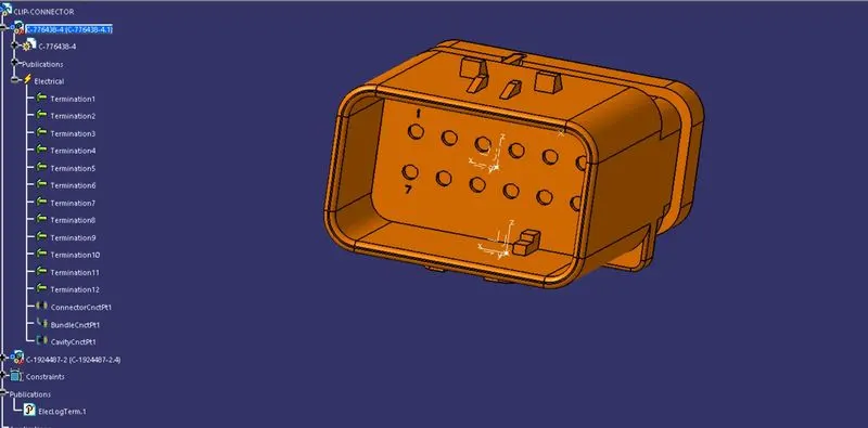
12-pole connector is shown above with all electrical parameters or defined.
creating the new product assembly and inserting both the connector and cavity.
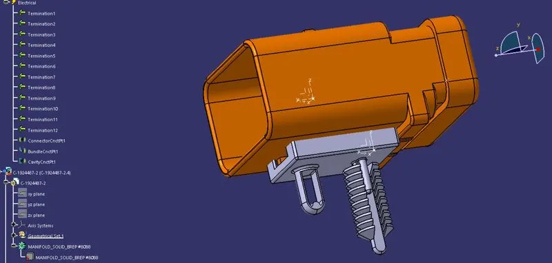
total assembly took into engine wiring harness context and mounted on top of the L-clamp.
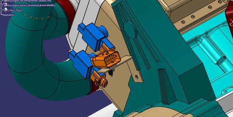
another angle is shown below
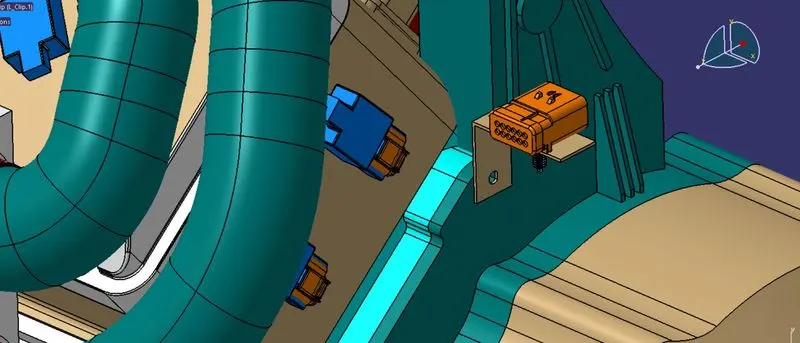
Now, we have to mount that electrically connected interconnection connector and cavity on a sheet metal bracket as shown in the above figure.
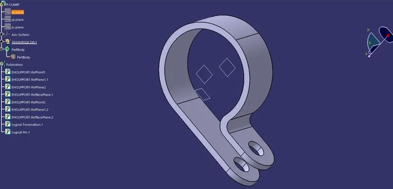
We have to mount 3 P-clamps also on the existing bolts of the engine so before that we have to define P-clamp electrically with geometrical parameters, entry and exit points on both the left and right side of the P-clamp as shown in below figure.
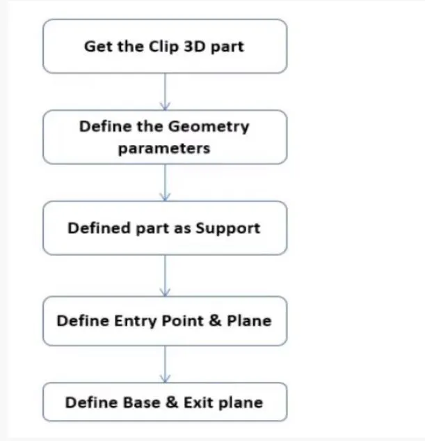
- The given clip was downloaded and opened in CATIA as a part file.
- And define two points that will be used as entry and exit points.
- after that, a plane has to be created at the points.
- A base plane has to be defined at a distance of 2 to 3 mm from the clip.
- again we define the exit point in the first definition as the entry point.
- finally, we got two entry and two exit points.
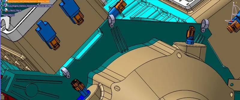
Guiding channel
guiding channel is created in mechanical parts design and imported into assembly and defined with electrical defined. like same tod channel is created as add in the assembly
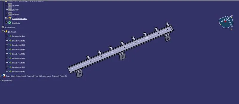
TOP CHANNEL
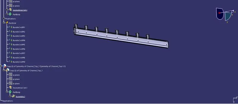
TOP AND BOTTOM IN ASSEMBLY WORKBENCH
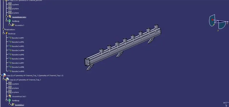
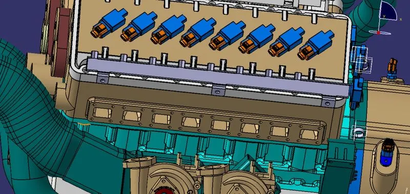
CHANNEL IS ATTACHED AND SHOW BELOW
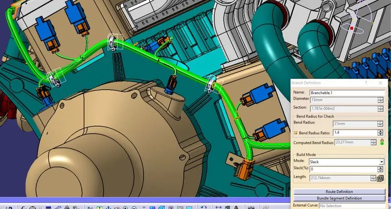
Here, we are routing the bundle segment from the interconnection connector to 3 P-clamps. The diameter for this routing path is 15mm and the bend radius ratio is assumed to be 1.4
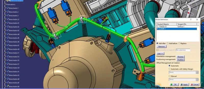
from the main bundle to the connector created an bundle split point and the link as been taken to the connector with a dia of 5MM and the bend rasio of 1.4
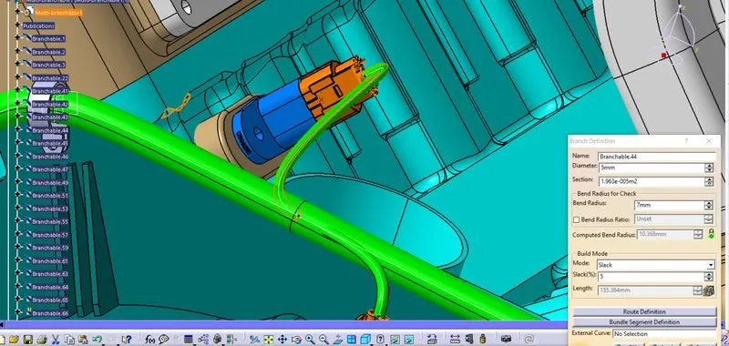
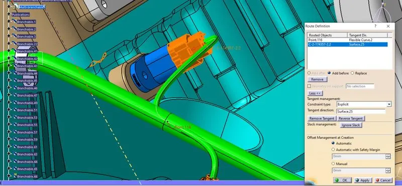
the same dia has been taken for the injector sensor image has been shown below for reference
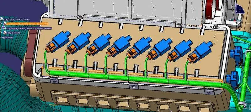
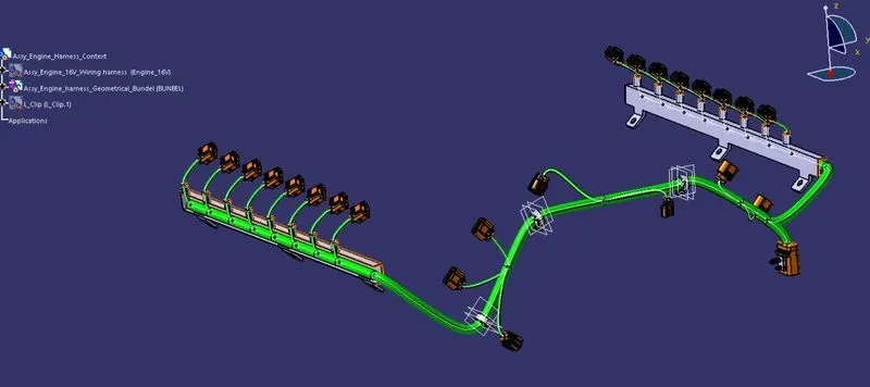
Here in below figure, we have done with whole wiring harness routing for the Bugatti V16 Engine. Now, we have to add protective coverings to all bundle segments and top shell of the guiding channel.
due to the high temperature in this area so we go with cotton taping on top of the Bundle
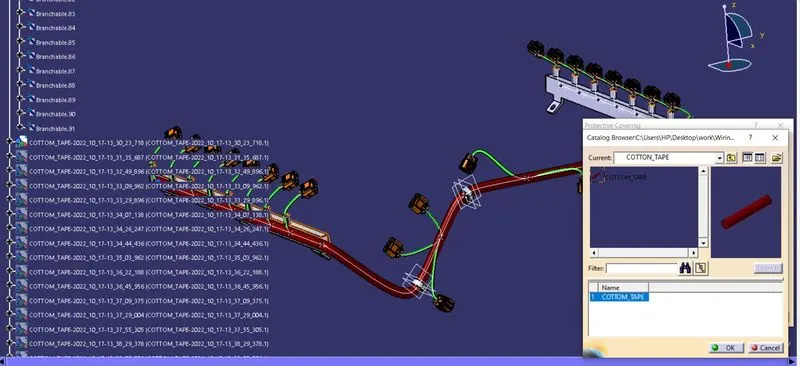
we also provided end extremity and start extremity for this model
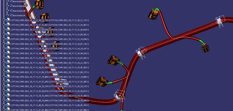
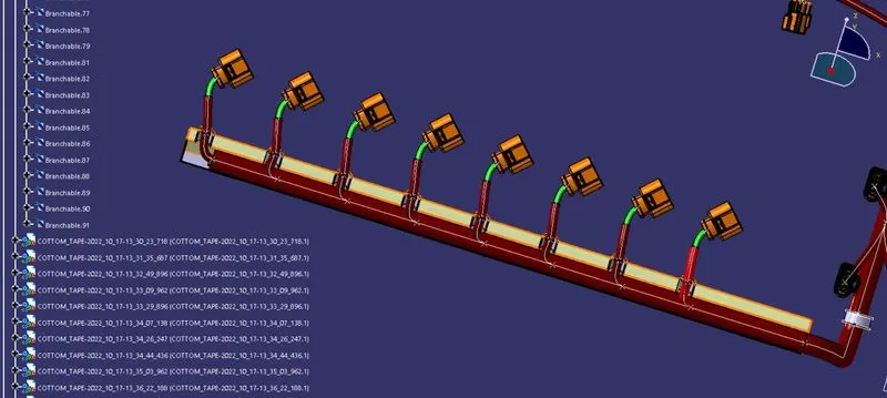
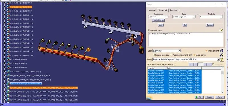
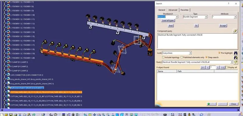
Selecting the 'True' option will show all the connected bundle segments while selecting the 'False' option will show all the non-connected bundle segments. Here, we have selected the 'True' option and searched for results. All the bundle segments are highlighted found showing that all the bundle segments are electrically connected as shown in the below figure.
The 'False' option will show all the non-connected bundle segments.
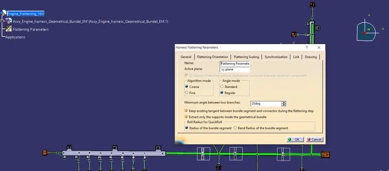
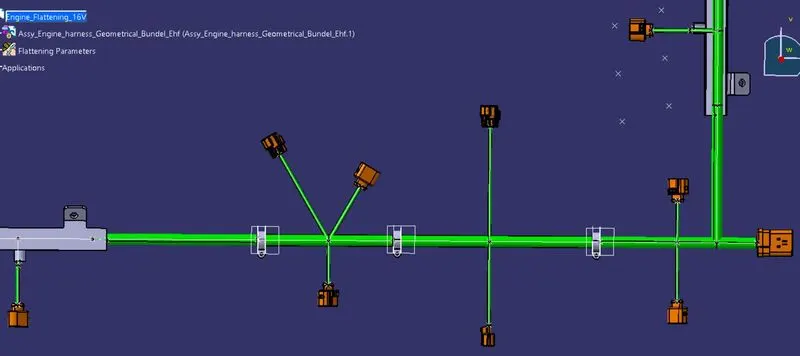
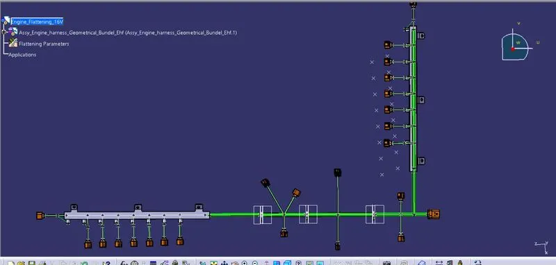
In this step, for creating flattened view we have to work in the Electrical Harness Flattening workbench of Catia V5. We should also make sure that the flattening file is saved in the same folder where other files of harness assembly are saved.
flattening parameters is shown bellow
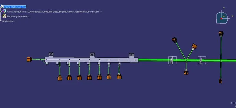
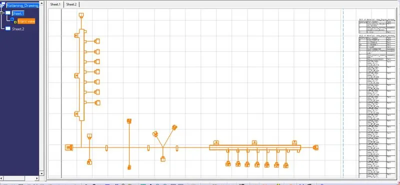
complete flattening is shown below the image.
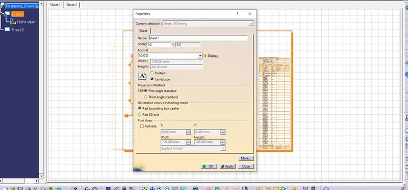
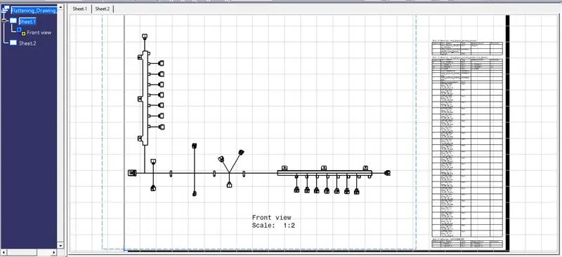
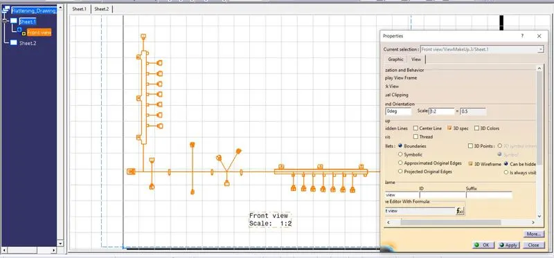
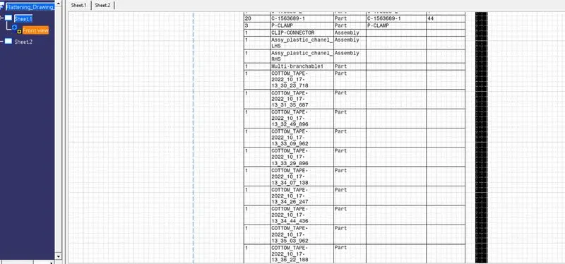
In the above figure, we are creating a new drawing file and defining all the necessary drawing parameters. We have to insert the front view of the Engine Harness Flattening Product file into the Drawing file.
Conclusion:
In this way, we have routed the wiring harness for the Bugatti V16 Engine. Also, prepared to flatten view drawing with a proper sheet in CATIA V5.