Project 1
ELECTRICAL DEFINITION
- All the individual connectors,channels, clips & clamps were opened in part design.
- Corresponding points, axis and planes were created.
- The parts then were opened in electrical part design where they were electrically defined.
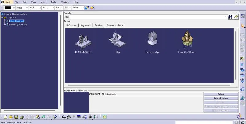
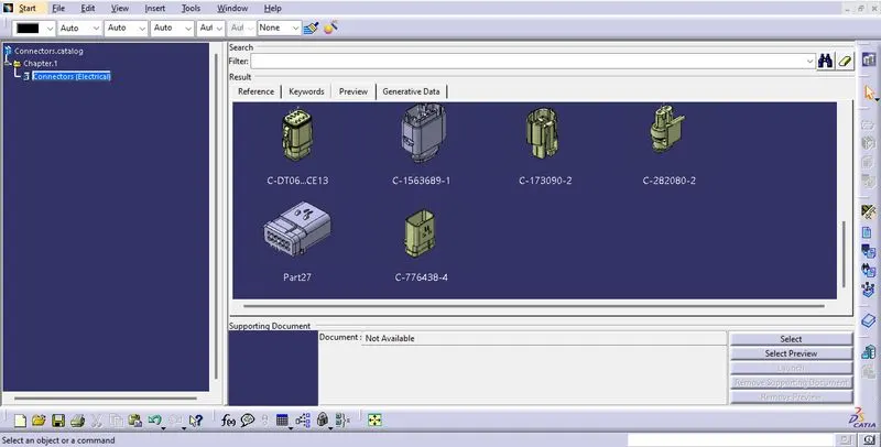
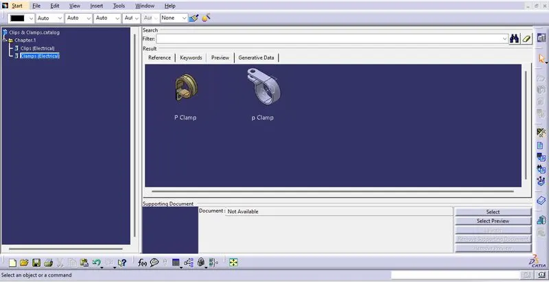
- All the connection points were established and were added to the catalogue.
PLACEMENT IN ASSEMBLY
- A contextual assembly was created where the external referance was opened.
- Another product for geometric bundle were created.
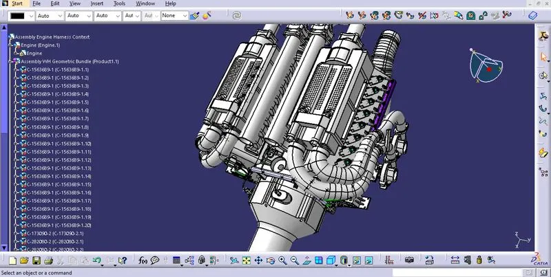
- All the connectors,channels, clips & clamps were tentatively placed on the reference within the geometrical bundle.
ROUTING
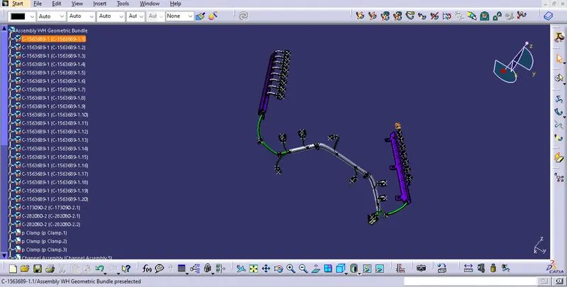
- Once all the components were placed in their respective positions, a multi branchable was defined in the wiring harness workbench.
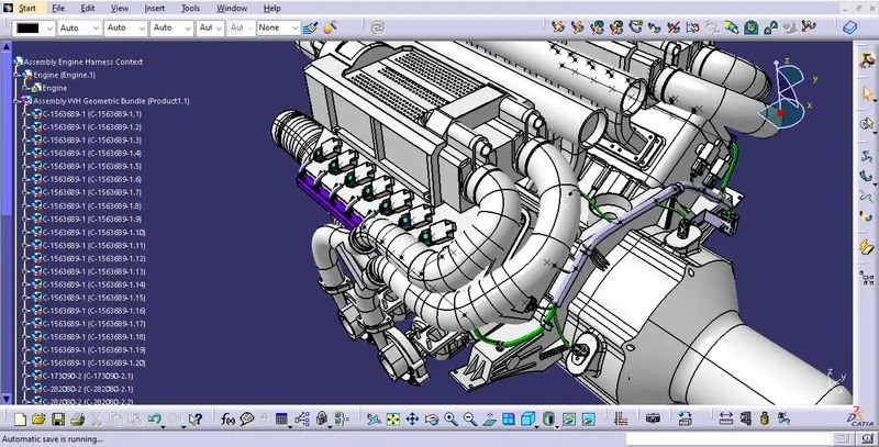
- All the components were routed providing enough clearances.
- Foulings were removed by providing slack, clips & clamps.
- Corrugated tubes were provided for protecting the bundles and to give an aesthetic appearance.
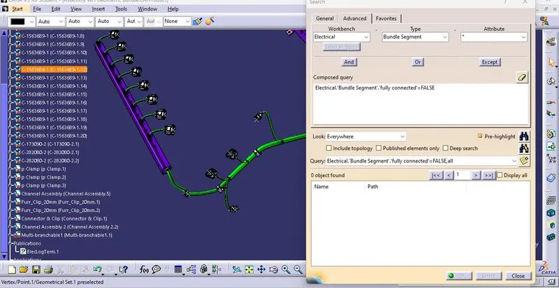
- Bundle connectivity was also checked and was found satisfactory.
FLATTENING
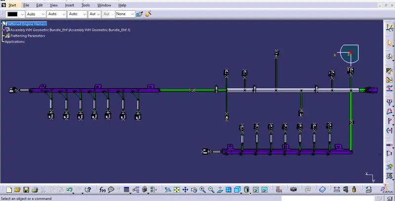
- After routing a new product file for flattening was created.
- All flattening parameters were defined.
- Then the harness assembly was extracted and flattened.
- The sub branches positions were altered using the rotate command.
DRAWING
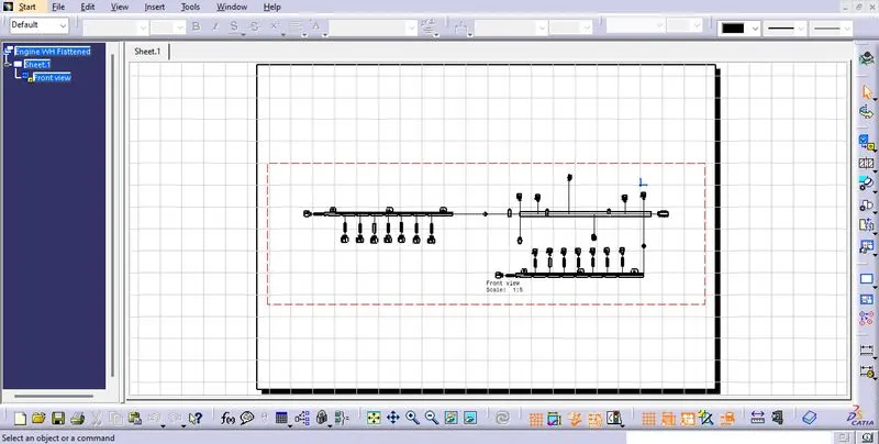
- A new drawing file was created.
- The flattened harness was projected on to the drawing by selecting the view.
- In order to view the bundles, the properties were altered to change the visibility of wireframe.
- The drawing was scaled down to fit the sheet size.