Project 1
| Title | Calculation of Seismic Load (IS 1893 - Part 1) | ||||||||
| Design Base Shear | VB | = | Ah W | kN | |||||
| Design Horizontal Acceleration Coefficient |
|
||||||||
| Ah | = | ||||||||
| Zone factor | Z | = | 0.1 | ||||||
| Soil Condition factor , Sa / g |
|
||||||||
| T | = | 0.09/SQURT D | |||||||
| Height of building | h | = | 21 | m | |||||
| Base dimension of building | Along X | = | 25 | m | |||||
| Along Z | = | 16 | m | ||||||
| T along X | = | 0.38 | s | ||||||
| T along Z | = | 0.47 | s | ||||||
| Sa / g | = | 2.500 | 2.878 | ||||||
| Response Reduction Factor | R | = | 5 | ||||||
| Importance Factor | I | = | 1.2 | ||||||
| Horizontal Acceleration Coefficient | Ah | = | 0.03 | ||||||
| Ah | = | 3 | % | ||||||
| Seismic Weight | |||||||||
| Area of Each floor | A | = | 400 | m2 | |||||
| Due to Dead Loads , Typical Floor | DL | = | 10 | kN/m2 | |||||
| W DL | = | 4000 | kN | ||||||
| Due to Dead Loads ,Roof | DL roof | = | 6 | kN/m2 | |||||
| ` | = | 3200 | kN | ||||||
| Due to Live Loads , Typical Floor | LL | = | 5 | kN/m2 | |||||
| W LL | = | 1000 | kN | ||||||
| Due to Live Loads , Roof | LL | = | 1.5 | kN/m2 | |||||
| W LL | = | 0 | kN | ||||||
| Total Seismic Weight | W | = | 38200 | kN | |||||
| Design Base Shear | VB | = | 1146 | kN | |||||
LOADING CALCULATION OF PRROJECT 1
AREA OF FLOOR ; 25X16 M
DEAD LOAD ON FLOOR =10KN/M2
DEAD LOAD O THE FLOOR= 1.8KN/M2
WT OF ROOF FLOOR= 25X16X 1.8=720KN
WT OF FLOOR: 25X 16X 10= 4000 KN
TOTAL WT OF DEAD OF 6 FLOOR = 24000 KN
TOTAL LOAD DL =24720 KN
LIVE LOA ON EACH FLOOR= 3KN/M2
UTO 6 FLOOR , T0TAL LIVE LOAD=400X3= 1200KN
ACTNG SEISMIC WT DUE TO LIVE LOAD=25% X1200 AS PERCLAUSE
LIVE LOAD= 300 KN
NO LIVE LOAD CTING ON TE ROOF =0 KN
TOTAL SEISMIC WT= 24720+300= 25020 KN
DESIG BASE SHEAR = AhXW
Ah = Z/2 X Sa/G/R/I
Vb= 1122 kn
WIND lOAD CALCULATION.
BASIC WIND SPEED OF BANGALORE (Vb)= 33M/S AS PER IS 875 PART 3
DESIGN WIND SPEED( Vz) = Vb.K1.K2.K3.K4
K1= RISK FACTOR = (TABLE 1 (6.3.1 ) = 1.0
K2= ERRAIN AND HEIGT FACTOR =(TABLE 2 .3.2.2) = 0.84 CATEGORY 4
K3= TOPOGRAPHY FACTOR = (6.3.3.10 1.0
K4=IMPORTANT FACTOR OF CYCLONIC REGION ( 6.3.4 )= 1.0
Vz = 33 x1.0x0.84x10x1.0
= 27.72 m/s assum 28 m/s
| Height | k2 | Vz | Pz | Pz in kN | ||
| 3.5 | 0.84 | 28 | 461.04 | 0.46 | ||
| 7.0 | 0.84 | 28 | 461.04 | 0.46 | ||
| 10.5 | 0.84 | 28 | 461.04 | 0.46 | ||
| 14.0 | 0.84 | 28 | 461.04 | 0.46 | ||
| 17.5 | 0.84 | 28 | 461.04 | 0.46 | ||
| 20.0 | 0.84 | 28 | 461.04 | 0.46 | ||
| 23.5 | 0.84 | 28 | 461.04 | 0.46 |
DESIGN OF SLAB ELEMENT USING MS EXCELL.
| Design of Slab (IS 456) | |||||||
| Span Shorter Direction (Clear) | ly | = | 5.00 | m | |||
| Span Longer Direction (Clear) | lx | = | 4.00 | m | |||
| Live Load on the Slab | LL | = | 3.00 | kN / m2 | |||
| Compressive stength of concrete | fck | = | 30 | N / mm2 | |||
| Yield strength of steel | fy | = | 415 | N / mm2 | |||
| Unit weight of concrete | Ƴc | = | 25.00 | kN / m3 | |||
| Unit weight of floor finish 100 mm | Ƴ | = | 22.00 | kN / m3 | |||
| Clear concrete cover | = | 25.00 | mm | ||||
| Bearing of slab | B | = | 250.00 | mm | |||
| Cl 24.1 | Span to effective depth ratio | l/d | = | 28 | |||
| Minimum effective depth | d | = | 178.57 | mm | |||
| Overall depth | D | = | 209.57 | mm | |||
| Provide Overall depth | D | = | 200.00 | mm | |||
| Dia of bars for short direction | Φ | = | 12 | mm | |||
| Dia of bars for long direction | Φ | = | 12 | mm | |||
| Effective Depth | d | = | 169.00 | mm | |||
| Loading on the slab | |||||||
| Dead Load of the slab (DL) | 10.00 | kN / m2 | |||||
| Super Dead Load | 4.00 | kN / m2 | |||||
| Live Load on the slab | 3.00 | kN / m2 | |||||
| Total Load on the slab (TL) | 17.00 | kN / m2 | |||||
| Design Load = (Total Load x Load Factor i.e. 1.5) | 25.50 | kN / m2 | |||||
| Effective Span | lx | = | 5.17 | m | |||
| ly | = | 4.17 | m | ||||
| Ratio | ly/lx | = | 0.807 | Two Way | |||
| T26/27 | |||||||
| 1.0 | ax | 1.10 | ay | ||||
| For negative moments (at top) | 0.047 | 0.035392 | 0.053 | 0.047 | |||
| For positive moments (at bottom) | 0.035 | 0.025327 | 0.04 | 0.035 | |||
| BM per unit width of slab | Mx = ax w lx2 | My = ay w lx2 | |||||
| For negative moments (at top) | 24.11 | 32.02 | KN-m/m | ||||
| For positive moments (at bottom) | 17.26 | 23.85 | KN-m/m | ||||
| Shear force , V | 0.5wlx | 65.90 | kN/m | ||||
| To check the effective depth of slab | |||||||
| Mu,lim | = | 0.138fckbd2 | |||||
| d | = | 76.32 | mm | ||||
| Depth of slab for shear force | |||||||
| T20 | τc,max | = | 4 | N/mm2 | |||
| τc | = | 0.3 | |||||
| Cl 40.2.1 | k | = | 1.2 | D=200mm | |||
| τc | = | 0.36 | N/mm2 | ||||
| τv | = | Vu / bd | |||||
| = | 0.39 | N/mm2 | |||||
| τv | < τc | < τc,max | |||||
| 0.39 | 0.36 | 4 | |||||
| SAFE | |||||||
| Determination of areas of steel | |||||||
| Mu = | 0.87fyAstd(1-Astfy/fckbd) | ||||||
| For Negative moments | Mu Top | = | 24.11 | ||||
| Ast | = | 494.98 | mm2/m | ||||
| For Positive moments | Mu Bot | = | 17.26 | ||||
| Ast | = | 354.21 | mm2/m | ||||
| Determination of distribution steel | |||||||
| Astmin | = | 0.12bd | |||||
| 202.8 | mm2 | ||||||
| Selection of reinforcing bars | |||||||
| Area of bars (Top steel) | = | 113.04 | mm2 | ||||
| Spacing | = | 228 | |||||
| = | 240 | mm | |||||
| Provide 12mm bars at a spacing 240mm | |||||||
| Area of bars (Bottom steel) | = | 113.04 | mm2 | ||||
| Spacing | = | 319 | |||||
| = | 300 | mm | |||||
| Provide 12mm bars at a spacing 300mm | |||||||
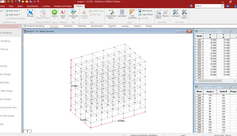
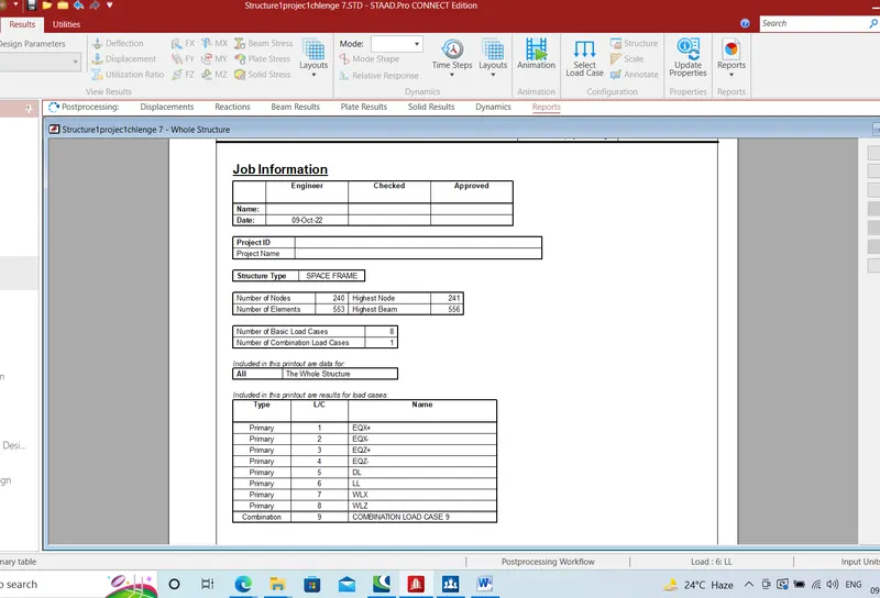
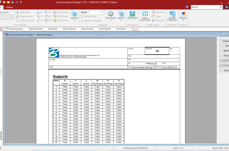
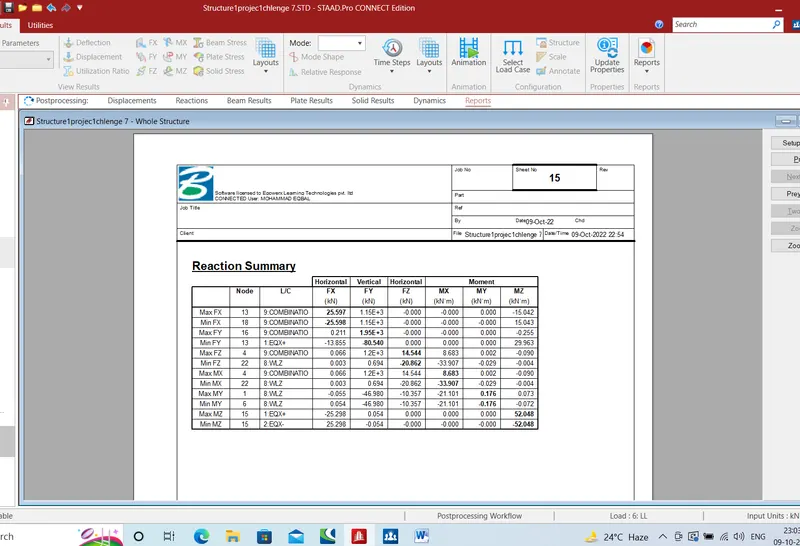
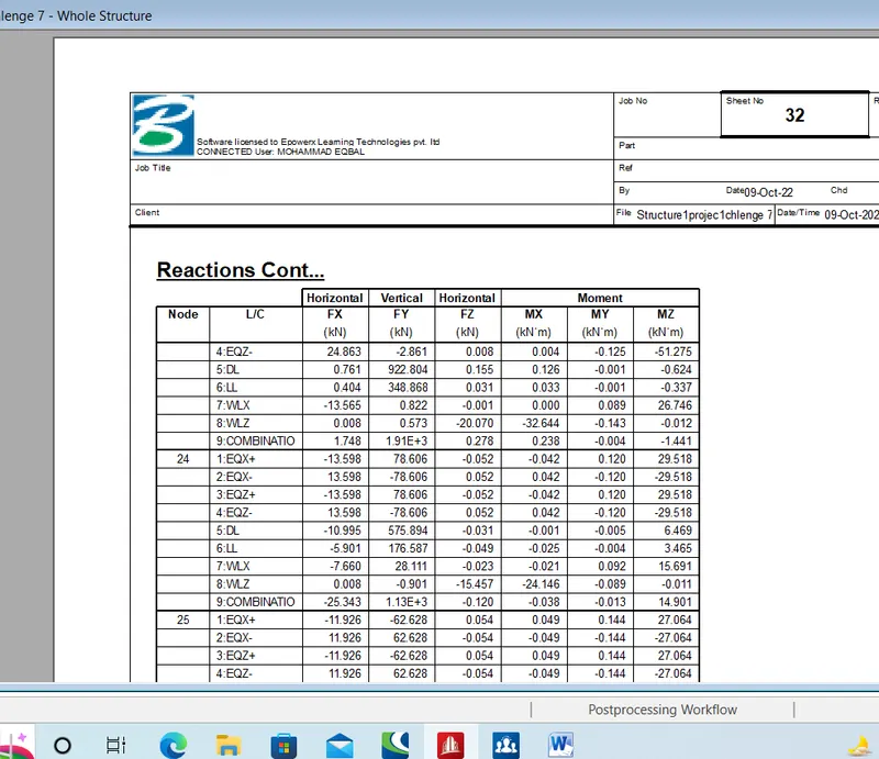
STRUCTURAL MODEL USING USING STAD PRO
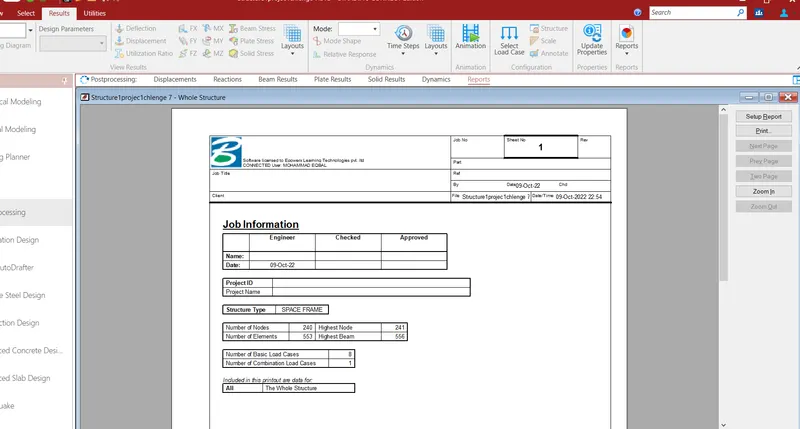
REPORT INPUT ND OUTPUT

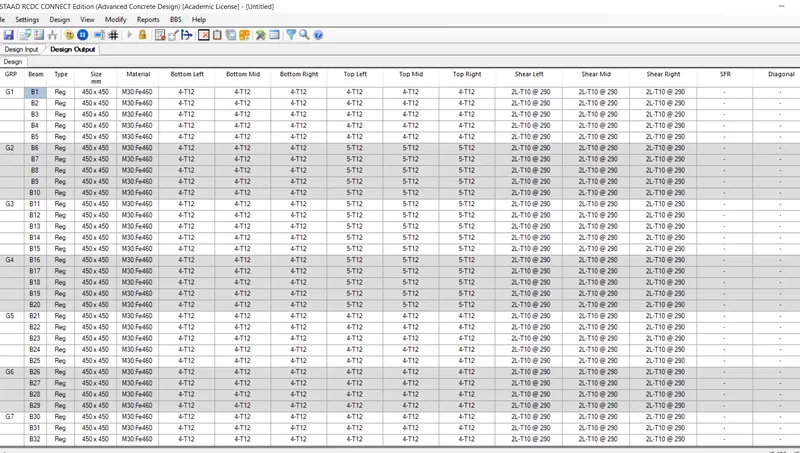
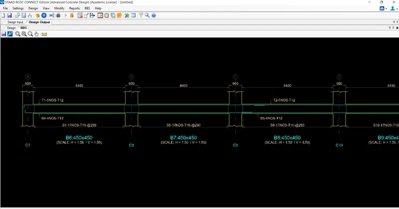
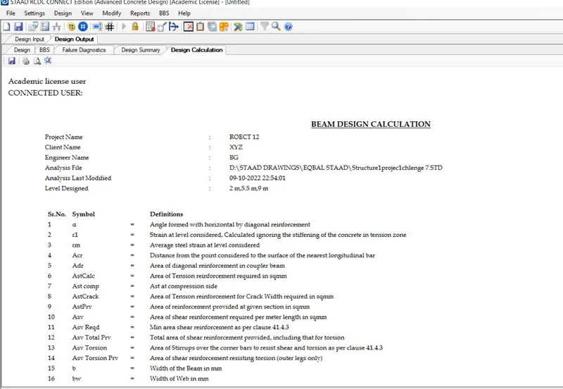
BEAM AND COLUNM DESIGN USING R.C.D.C
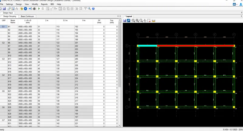
BEAM DETAIL WITH TOP AND BOTTOM REINFORCEMET
BEAM BBS
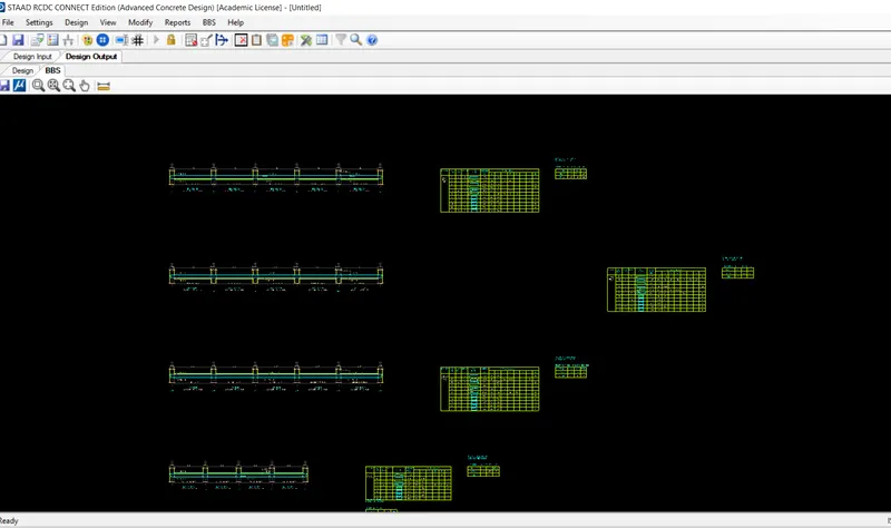
BEAM BBS
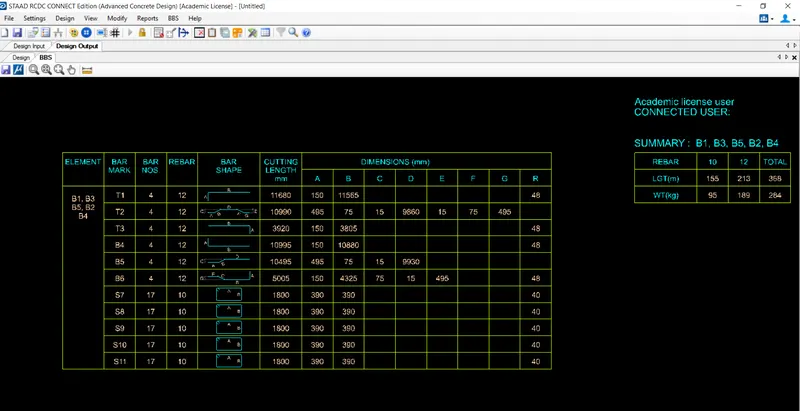
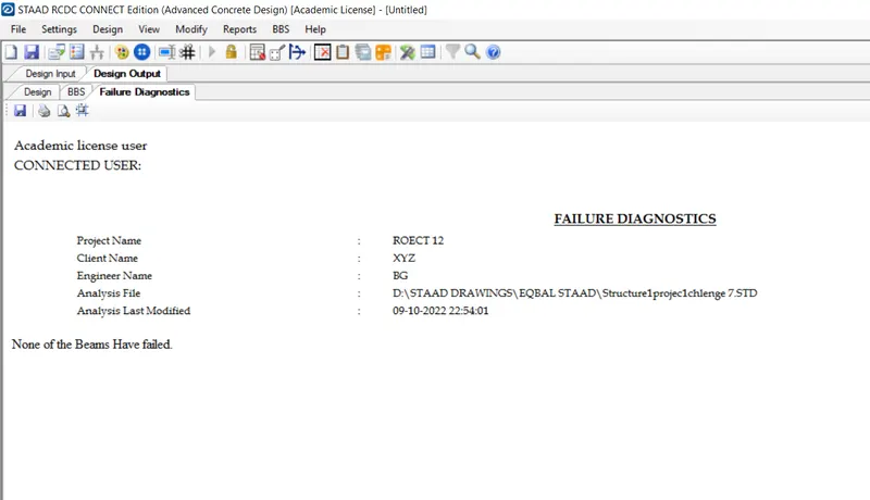
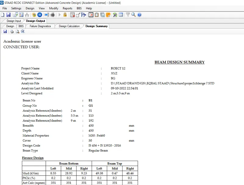
DESIGN CALCULATION
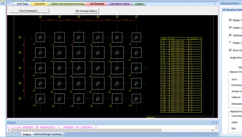
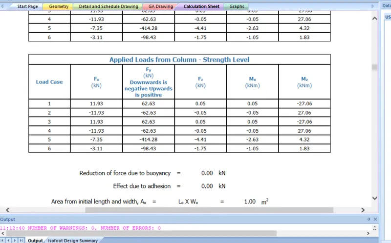
FOOTING DESIGN USING STAAD FOUNDATION
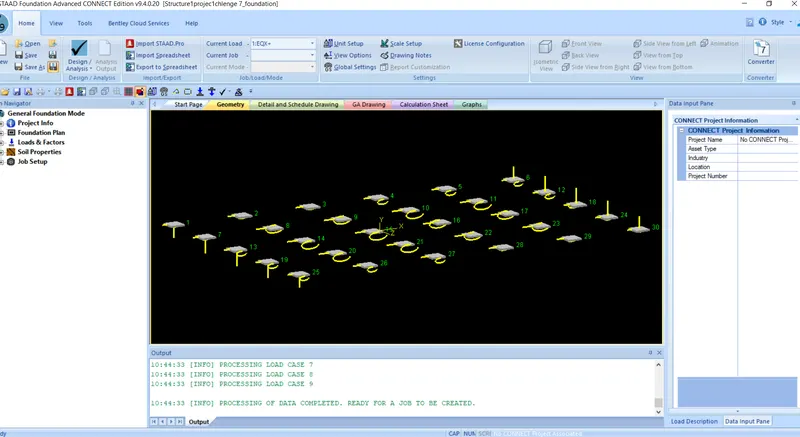
SOLATED FOOTIG DESIGN AND CALCULATION
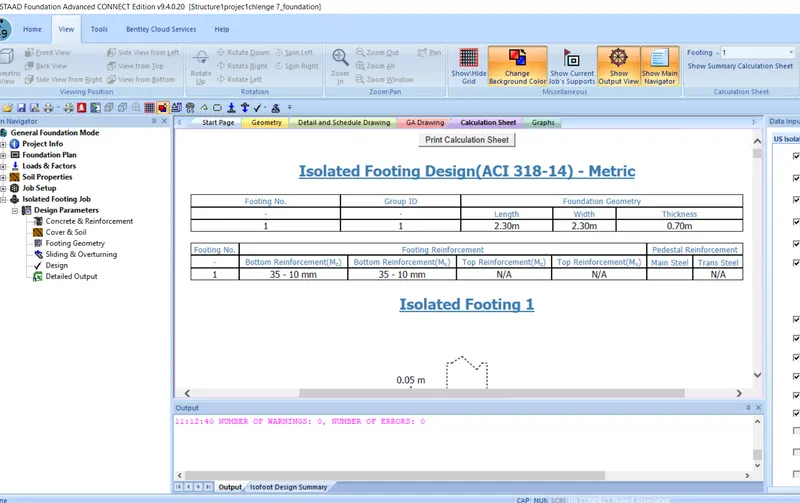
FOOTING LAYOUT