Project 1
Aim:
Create a stateflow or Simulink model for the following flowchart.
Load the .mat file into the workspace.
The input to the model would be the power demand.
The output should be:
- Fuel cell power
- Battery power
- FC Operating state (running, standby)
Create plot of these outputs against time.

Analysis:
By observing the flow chat we can see the inputs, outputs and Conditions
- Inputs:
- Power demand
- Outputs:
- Battery Power
- FC power
- Conditions:
There are 3 conditions according to the flow chart
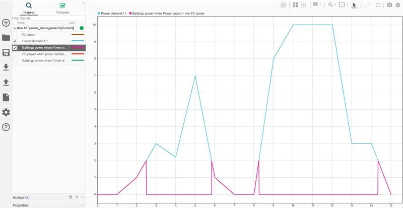
- Conditions-1: When the power demand is less than the min FC power - When the input power demand is less than the min FC power, than the power is delivered by the Battery alone and FC is in stand by position i.e., OFF
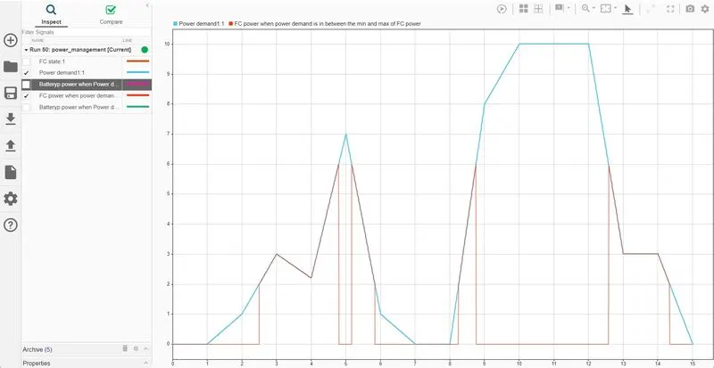
- Condition-2: When the power demand is greater than the min FC power and lesser than the max FC power - When the input power demand is greater than the min FC power and lesser than the max FC power the FC is ON and Battery is OFF i.e., the power demand is supplied by FC alone.
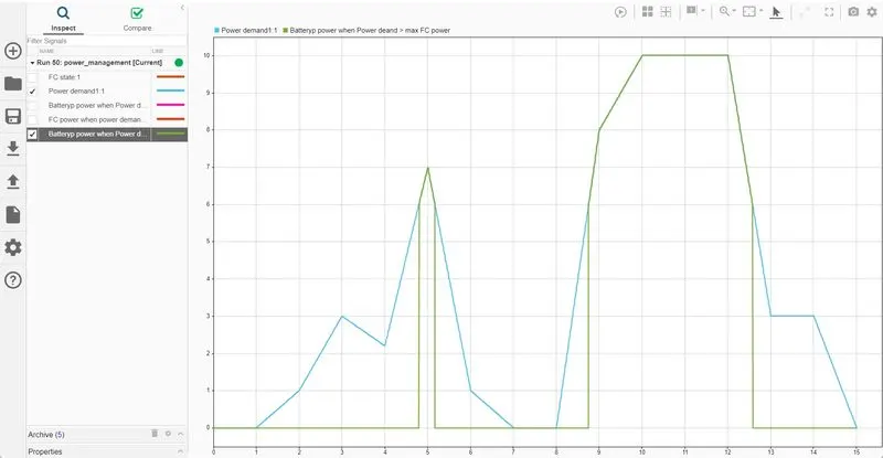
- Condtion-3: When the power demand is more than the max FC power - When the input power demand is more than the max FC power than the FC will OFF and Battery will ON i.e., power demand is supplied by the Battery alone.
Here we can observe that the Power demand supplied by the battery is in two contitions i.e., power demand is less than the min FC power and Greater than the max FC power.
Assumptions:
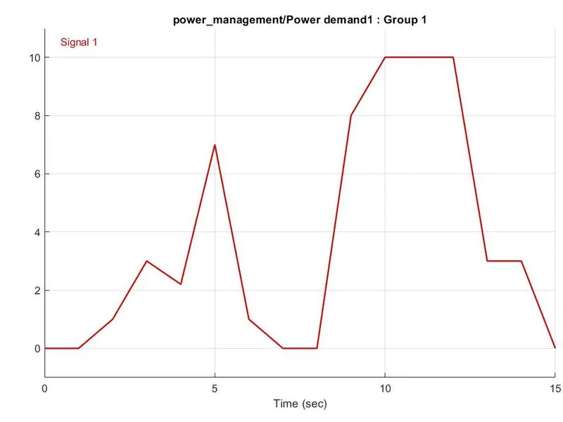
Max power demand = 10Kw
Max Battery power = 15Kw
Min FC power = 2kw
Max FC power = 6Kw
Simulation:
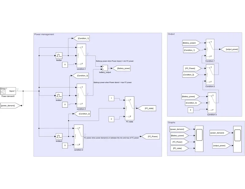
Design:
Step-1: Place signal builder block and creat the requird power demand signal
Step-2:
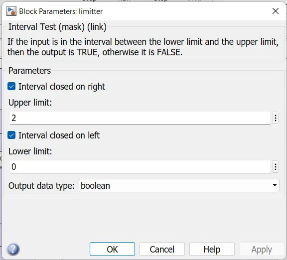
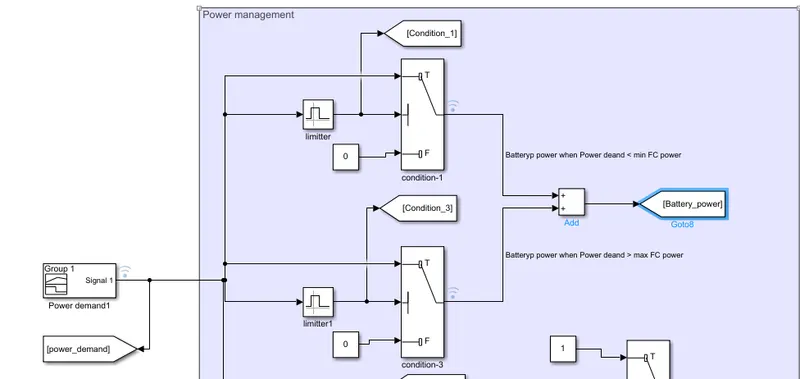
Place the Intervel test block and set the upper and lower limit which the battery can supply i.e., whrn the Power demand is less than the min FC power. So that the upper limit will be 2 and lower limit will be 0.
Step-3:
Useing the conditional switch make shure that only power demand limit which is set in the intervel test block. As shown below
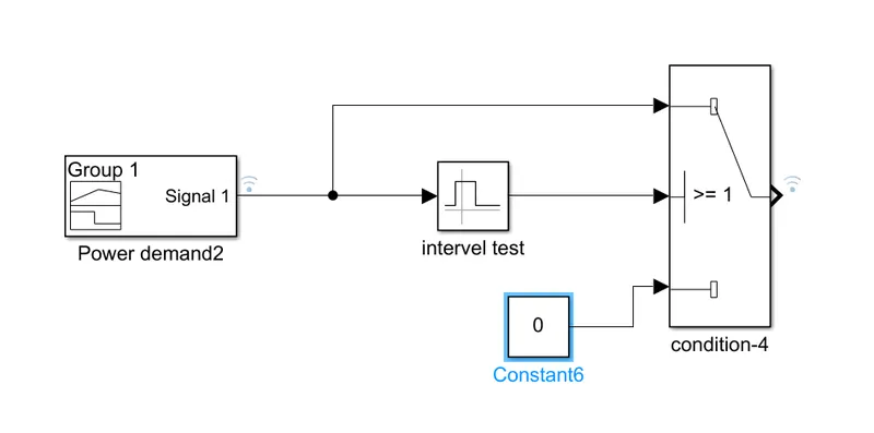
Step-4:
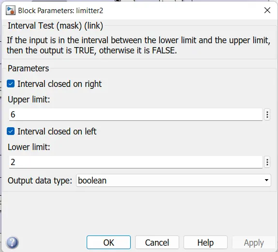
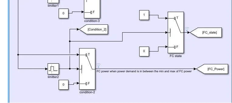
Repeat the step 2 and 3 for the condition-2 i.e., greater than the min FC power and lesser than the max FC power, the Fc should supply the power demand. Hence upper limit as 6 and lower limit as 2.
Step-5:
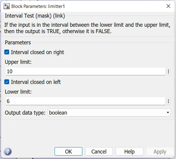
Repeat the step 2 and 3 for the condition-3 i.e., greater than the max FC power, the battery should supply the power demand.Hence lower limit as 6 and upper limit as 15.
Step-6:
Sice the battery shoud supply the power demand in both conditions i.e., lesser than the min FC power and greater than the max FC power so we can use the Add block to add the battery powers in 2 conditions. So that the battery power is supplied in both conditions.
Step-7:
For the FC state use the switch and condition is given by the FC Intervel test block.
Step-8:
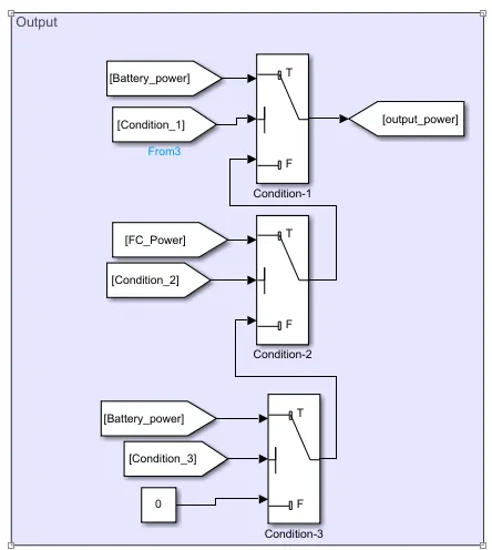
To get the combained output of all conditions following the logic is designed
Working:
The output of Intervel test block is boolean i.e., 1 or 0. When the given condition gets true its output will be 1 or else 0. Let us assume that the input power deamnd is less than 2 say 1, accoring to the Inverel test blocks limmits the condition-1 block gets high as its imites are betten 0 and 2 and all other condition blocks are Low as they didn't meet the conditons of the Intervel test blocks. When it gets high the port 1 is send out i.e., is battery power which is power demand.
It is shown in below
Now let the power demand is greater than Min FC power and lesser than the Max FC power say 5, so the intervel test block-2 is high and all other are low. the power from that switch is send to the out port.
It is shown in below
Now let the power demand is greater than max FC power say 8, so the intervel test block-1 is high and all other are low. the power from that switch is send to the out port.
It is shown in below
Here we need to take care that for condition-1 and 3 battery power should be the out so we can add the both conditions power output so that we can get the total battery power as out. We can observe that never the both the conditions are going to high at a time if condition-1 is high condition-3 is going to be low and vice versa. So we should not worry about the resultant power out i.e., if the both are high the resultant added power is is going to more than the power demand, it is not going to happen.
The output is designed in such a way that when the condition 1 is satisfied the battery power is send if not if the condition 2 is satisfied FC power is going to send if not if the condition 3 satisfied the Battery is going to send out if not zero is send out.
Results:
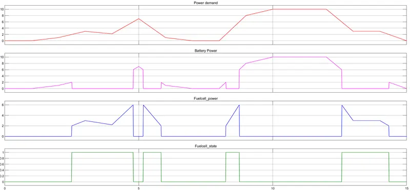
We can observe that battery power is supplied in both the conditions i.e., When the power demand is less than the min FC power and When the power demand is more than the max FC power in the Battery power graph
We can observe that FC power is supplied in the condition When the power demand is greater than the min FC power and lesser than the max FC power in the Fuelcell-power graph
State of the Fuel cell can be observed in Fuelcell_State graph. when the power demand is less than the min FC power value the FC status is OFF i., Low()0 and when the Power demand is breater than the Min FC the FC status is ON i.e., High (1) and when the power demand is more than the max FC power the FC status is OFF i., Low(0)
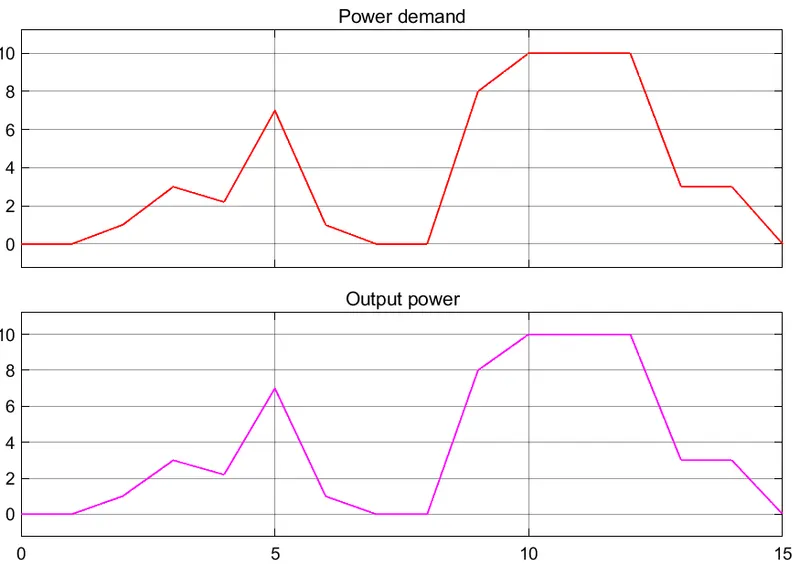
Final Output power and Input power demand are in same shape. That is the power demand is shared by the both the FC and Battery according to their conditions.
Conclusion:
We can conclude that the Power management between the FC and Battery according to their conditions is achieved.