Project 1
Design a multi-storey Residential Building located in Bangalore using STAAD Pro Connect Edition. The specification must be as follows:
|
Building floors |
G + 6 + R |
|
Plan dimension |
B = 25m, L = 16m |
|
Storey Height |
h = 3.5m |
|
Soil |
Hard soil |
|
Use |
Residential Purpose |
|
Safe Bearing Capacity |
180kN/m2 |
|
Maximum slab thickness |
150mm |
Assume suitable sections for structural elements. Follow IS456, IS1893 and IS 875
- Prepare a Design Basis Report for the project
- Create structural model using STAAD Pro Connect Edition
- Prepare DL, LL, WL and EQL load calculations as per IS 875 standards
- Design slab element using MS – Excel
- Design beam and column element using STAAD RCDC. Attach the design calculation report.
- Design Foundations using STAAD Foundation.
- Prepare bar bending schedule for beam and column using STAAD RCDC
Attach necessary sketches and drawings wherever required.
All stipulations, assumptions and design parameter must adhere to Indian Standards.
1. Prepare a Design Basis Report for the project
Design Basis Report is attached in .docx format.
2. Create structural model using STAAD Pro Connect Edition
Open the Structural wizard
Select Frame model> Bay frame
Enter the required parameters:
Length = 25m
Height = 24.5m
Width = 16m
No. of bays along length = 5
No. of bays along height = 7
No. of bays along width = 4
Assign property Assign material Assign supports
Go to property section
Click on Define material
Select the section> Rectangular
Select the material type> concrete
For the rectangular section enter YD & ZD in column below
Click add and close
Select the material type and assign to the selected view for the support
Click on the support
Click on create
Select type of support do we want to assign the section
Click on add close
Assign loads
To assign loads go to the loading tab
Add definitions (Wind, Seismic etc.)
Add load cases details as per the requirement (viz. DL, LL, EQ etc.)
Select the load type and add the loads (viz. Member load, self-weight etc.)
Select the members and assign the designated load
Go to the Loading tab> Definitions> Seismic Definition
Click on New, select the seismic code and assign the seismic parameters
Then click on Add and provide the floor weights as calculated in the previous question
After adding the floor weights, go to Load Cases Details> Add
Add the seismic loads in X and Z direction
Specify Type of Analysis
Run Analysis
3. Prepare DL, LL, WL and EQL load calculations as per IS 875 standards
Dead Load
Assuming 150mm thick slab thickness
Dead load of slab = Unit weight of concrete x slab thickness
= 25 x 0.15
Dead load of slab = 3.75kN/m2
Dead Load of beams
Considering the beams of cross-section 300 x 500 mm.
Dead load of beams = Unit weight of concrete x cross section of beam
=25 x 0.3 x 0.5
= 3.75kN/m ≈ 4kN/m
Dead load of beams = 4kN/m
Superimposed loads of partition walls
Assuming 230 mm thick brickwork.
Height of the brickwork = floor height = 3.5m
Therefore,
Dead load of brick masonry partition = Unit weight of masonry brick x wall dimension
18 x 3.5 x 0.23 = 14.49 kN/m ≈ 15kN/m
Superimposed loads of partition walls = 15kN/m
Live Load
As the proposed project is a hospital building, the IS 875 PART 3 states different live load values for different rooms within a hospital that are listed below:
|
OCCUPANCY |
LIVE LOAD kN/m2 |
|
All rooms and kitchen |
2.0 |
|
Toilets and Bathrooms |
2.0 |
|
Balconies |
3.0 |
|
Corridor, Passages |
3.0 |
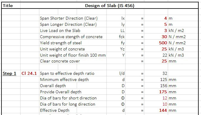
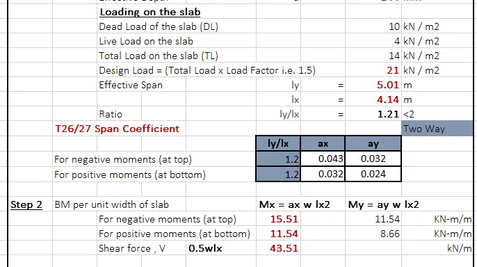
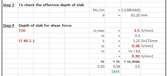
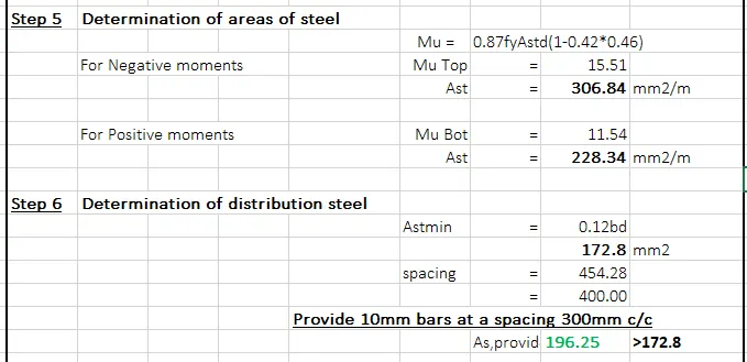
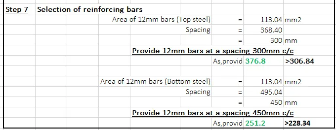
4. Design slab element using MS – Excel
The design of an interior panel slab is shown as below using MS-Excel
5. Design beam and column element using STAAD RCDC. Attach the design calculation report.
BEAM DESIGN
Open STAAD RCDC
Start a new project
Provide the necessary details and select the Design Element as Beam
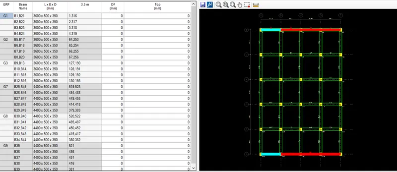
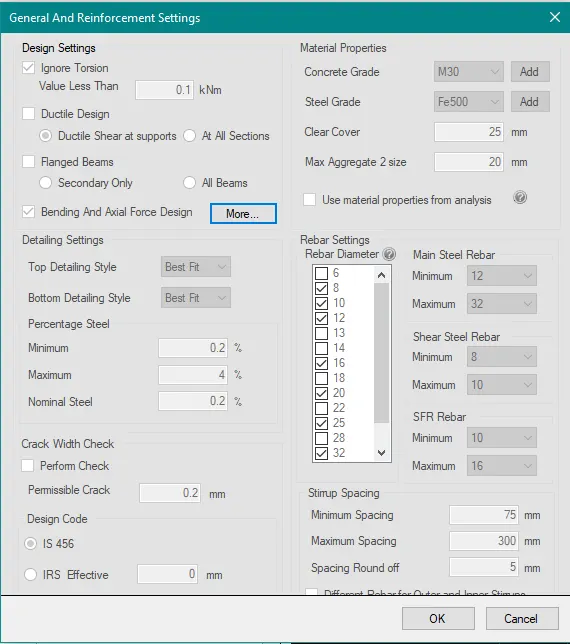
Go to Settings> General and Reinforcement Settings
Select M30, Fe500
Select main and shear steel bar sizes
Provide minimum and maximum reinforcement
Go to Design> Run Design
Select the respective load types
Go to Reports> Design Calculation
Select the Beams to be included in the report
Design calculation report is attached in .PDF format
COLUMN DESIGN
Open STAAD RCDC
Start a new project
Provide the necessary details and select the Design Element as Column
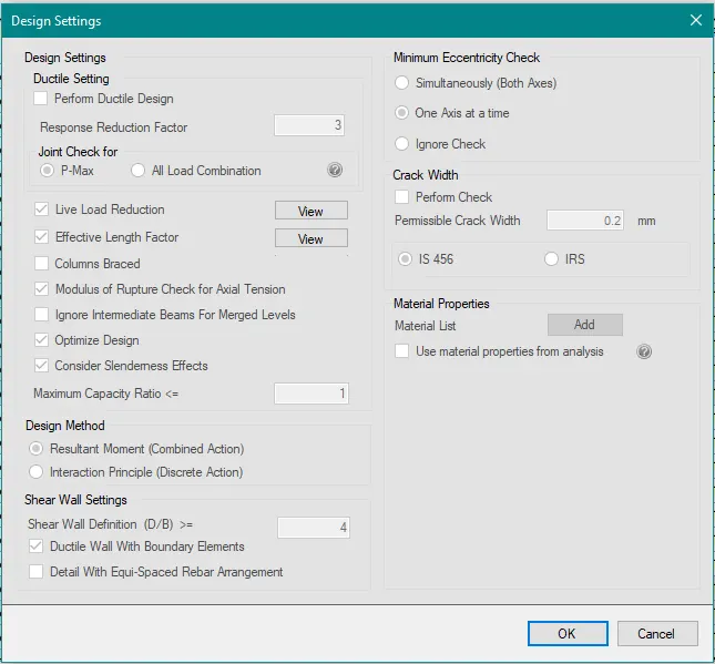
Go to Settings> Design Settings
Provide the necessary details
Go to Settings> Reinforcement settings
Select main and shear steel bar sizes
Provide minimum and maximum reinforcement
Go to Design> Run Design
Select the respective load types
Go to Reports> Design Calculation
Select the Columns to be included in the report
Design calculation report is attached in .PDF format
6. Design Foundations using STAAD Foundation.
Go to Foundation Design
Select the primary load cases
Open STAAD Foundation Advance
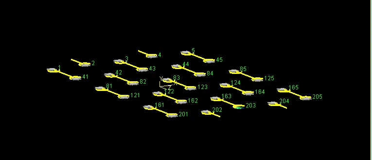
Go to Unit Setup> Select the IS Units
Go to Loads and Factors> generate Load Combination
Select Indian Code and Generate Service and Ultimate load combination
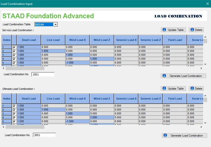
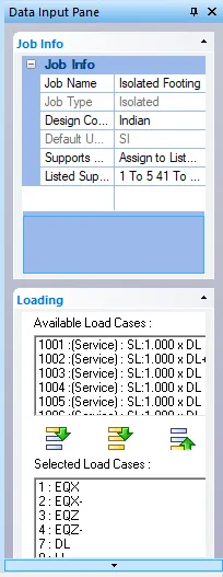
Go to Job Setup> Create New Job
Select the Isolated footing, Indian Code etc.
Include the primary load cases and ultimate load case
Create Job
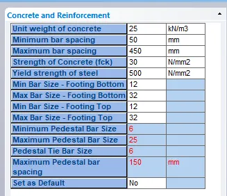
Go to Isolated Footing Job> Concrete and Reinforcement
Provide the necessary details asper the project
Go to Cover and soil and footing geometry
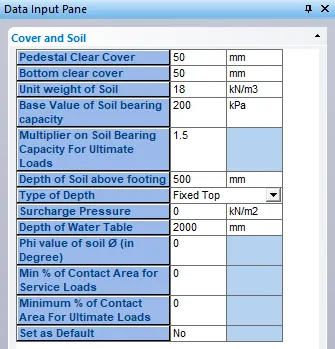
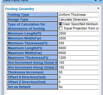
Click on Design
7. Prepare bar bending schedule for beam and column using STAAD RCDC
After performing the design of beam and column generate BBS for both elements
Go to BBS> Generate BBS
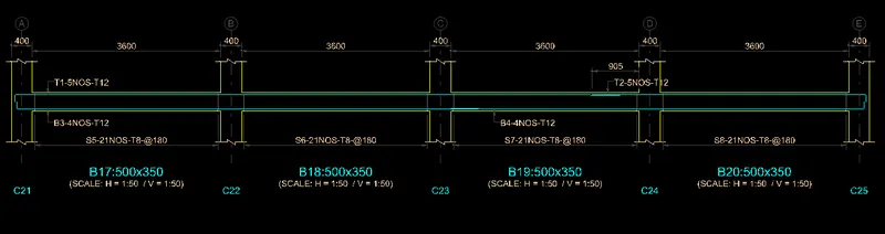
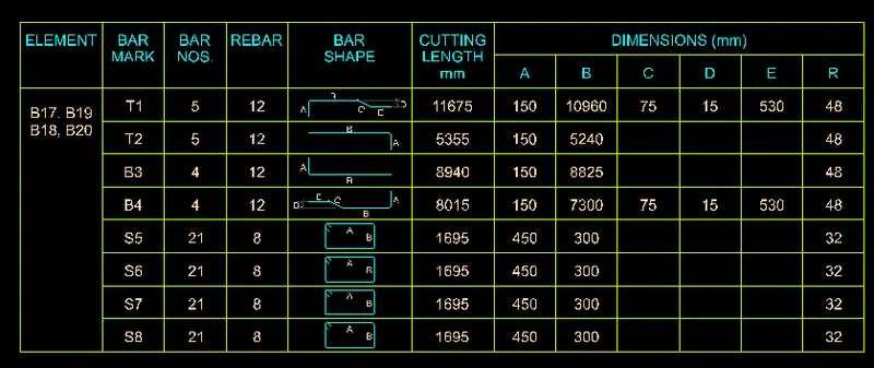
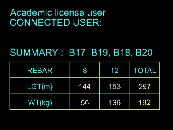
Select All beams or specified beams ( here only 1 continuous beam BBS is attached)
Click Generate
BBS FOR BEAM
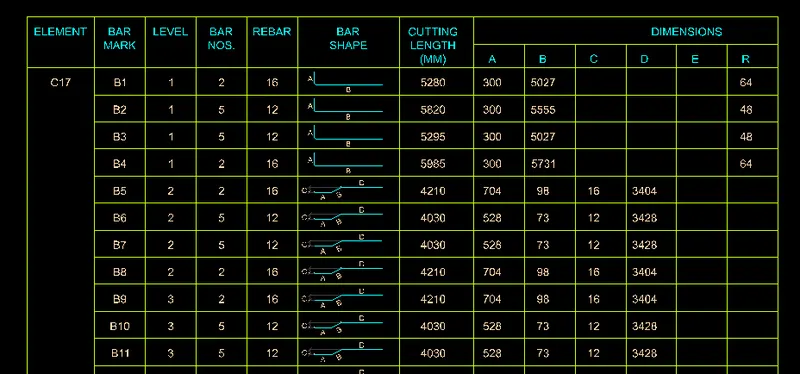
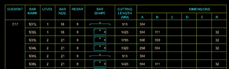
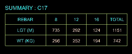
BBS FOR COLUMN
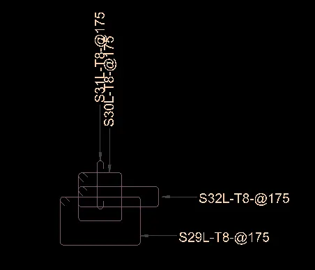
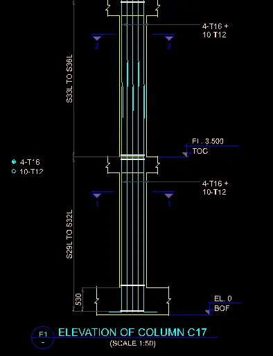
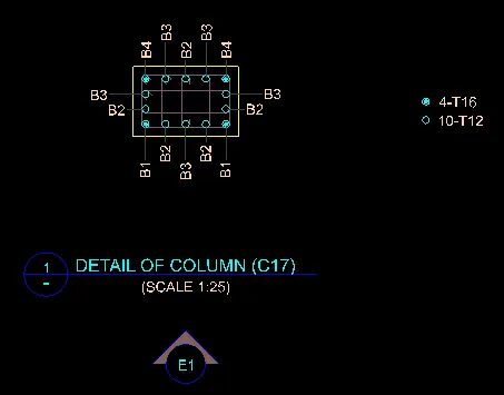
Column C17 of level 1 only is shown here
Longitudinal reinforcement
Shear reinforcement