Project 1
Project 1
AIM:
- In order to properly route the wiring harness for the specified engine, it is essential to apply all relevant packaging guidelines and industry best practices acquired throughout this course.
- Furthermore, the application of protective coverings should be implemented as necessary to ensure optimal performance and safety.
DESIGN CRITERIA AND PACKAGING ASSUMPTIONS:
- Wiring harness routing must prioritize manufacturing efficiency, accessibility, and the ease of removal and maintenance for both the attached equipment and the wiring harnesses.
- It is essential to avoid routing through small structural holes and openings in order to minimize chafing and handling of the wiring harness during installation.
- Additionally, harness routing and clipping should be positioned outside the Operator's blind zone during both assembly and service operations.
- Routing arrangements must provide adequate protection against potential damage that may result from common misuse, such as being manipulated by hand or serving as temporary support for test equipment.
- Extra slack should be incorporated into the harness design to accommodate surrounding elements and bending requirements, ensuring that the routing adheres to clearance specifications with adjacent components.
- It is critical to refrain from routing the harness over bolts or in proximity to bolted joints, as this may lead to damage or puncturing of the harness.
- Harnesses should also be kept away from panel mounting screws.
- Moreover, it is advisable to avoid routing near sharp edges; if avoidance is not feasible, appropriate protective measures should be implemented for the harness.
- The maximum allowable distance between two clips along a straight branch of the harness is 200 millimeters.
- Clips and clamps must be provided if the harness is expected to bend at multiple locations, while the use of excessive sheet-metal brackets should be minimized.
- The length of each branch should exceed 50 millimeters, ensuring that the minimum distance between a clip and its associated branching point is no less than 25 millimeters.
- Furthermore, a minimum separation of 50 millimeters should be maintained between two branch breakouts.
GIVEN COMPONENTS:
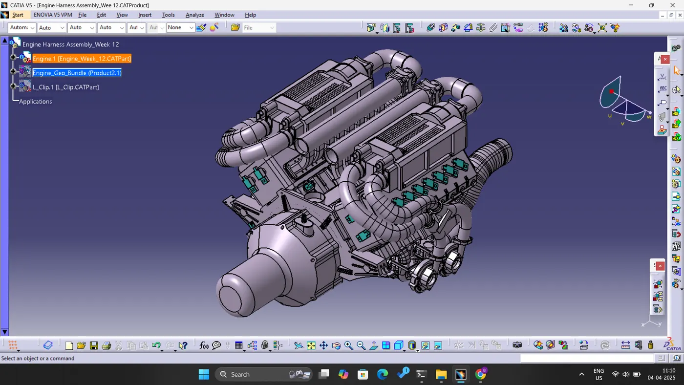
- Engine:
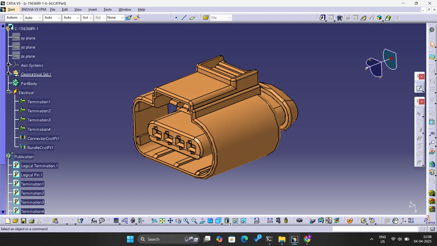
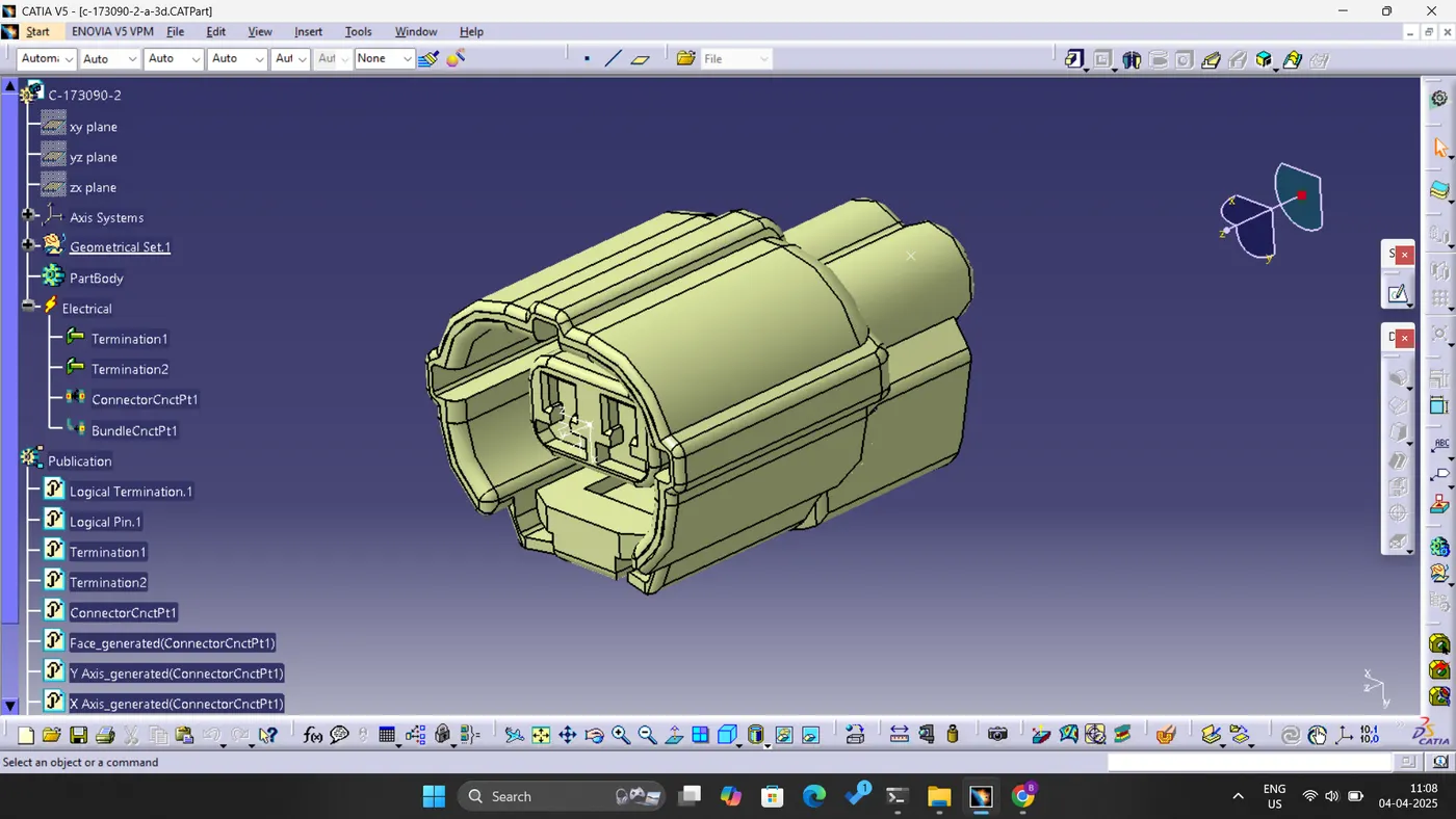
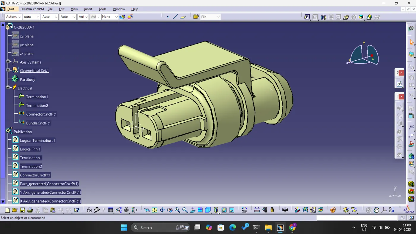
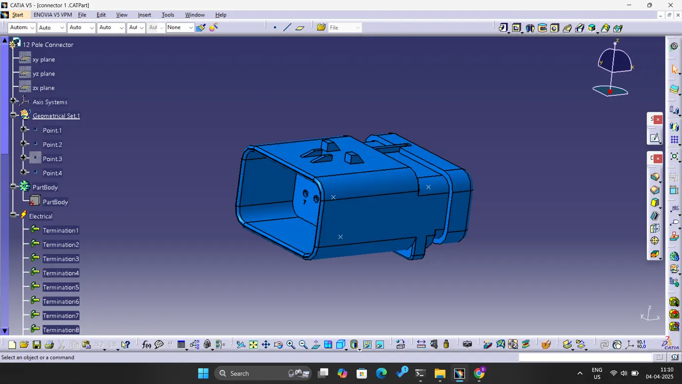
- Connector:
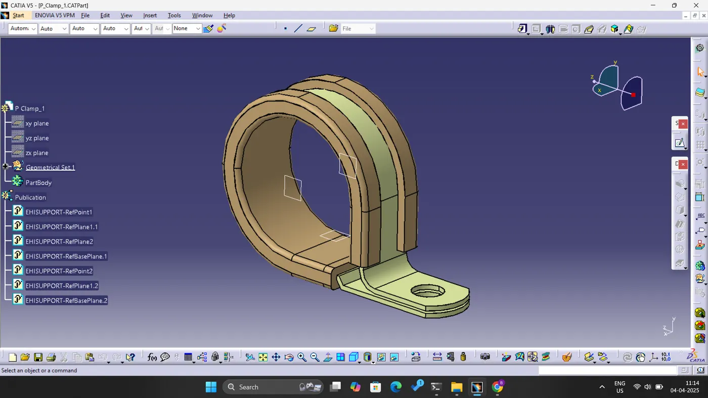
- P-clip:
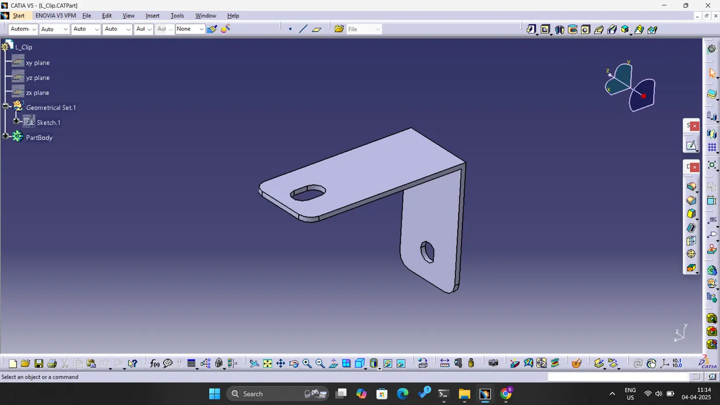
- L-clip:
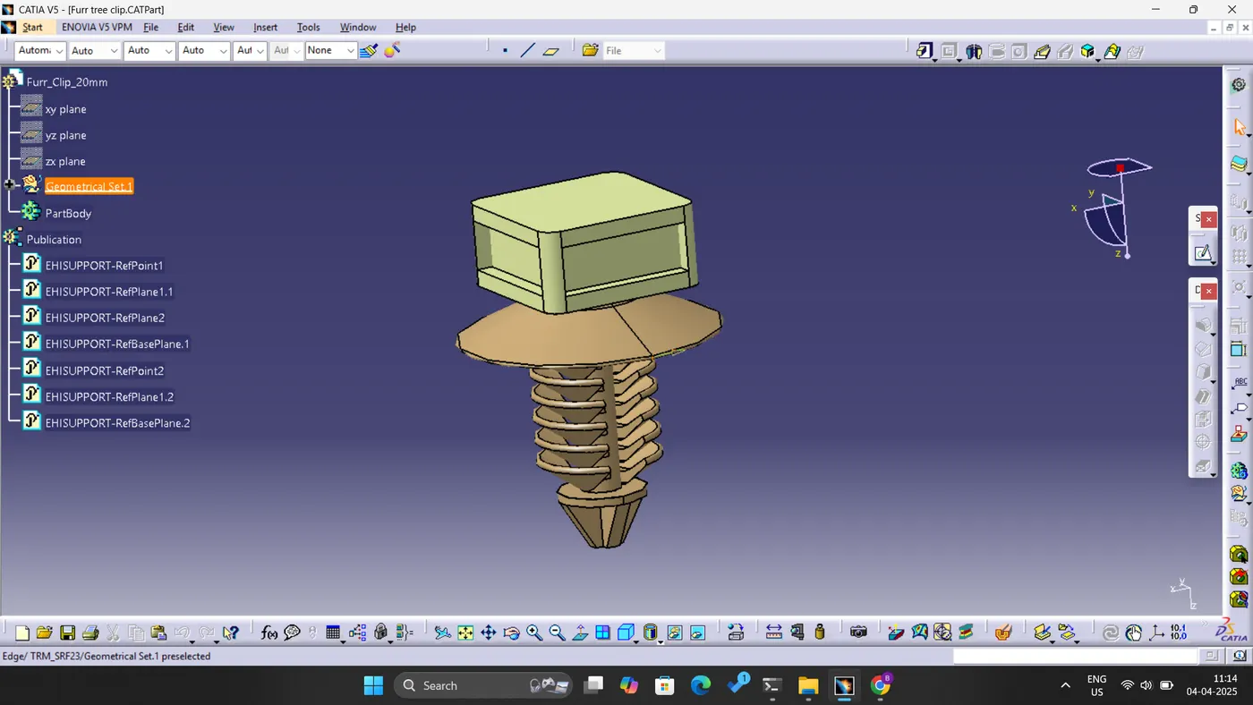
- Fur Tree Clip:
- Cavity Clip:
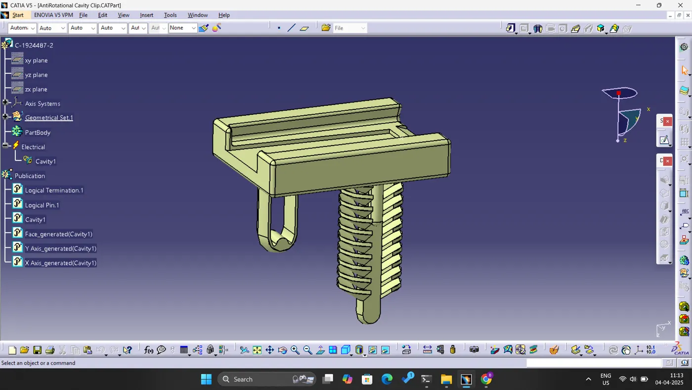
- Channel Top and Bottom:
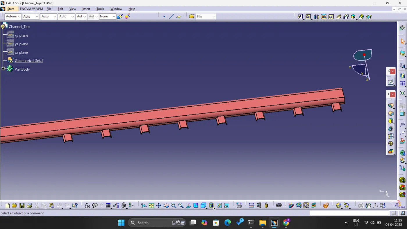
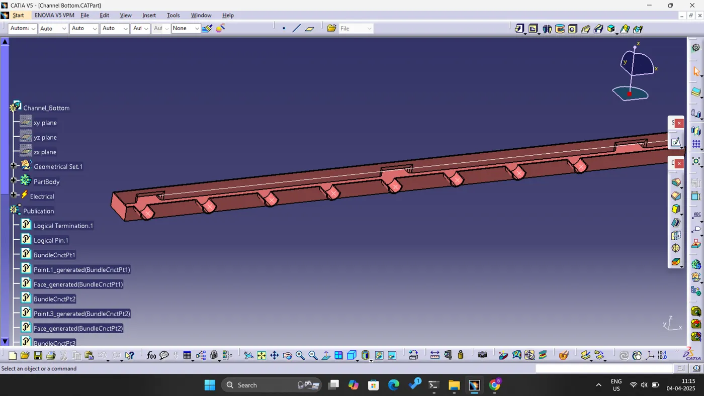
WIRING HARNESS ROUTING:
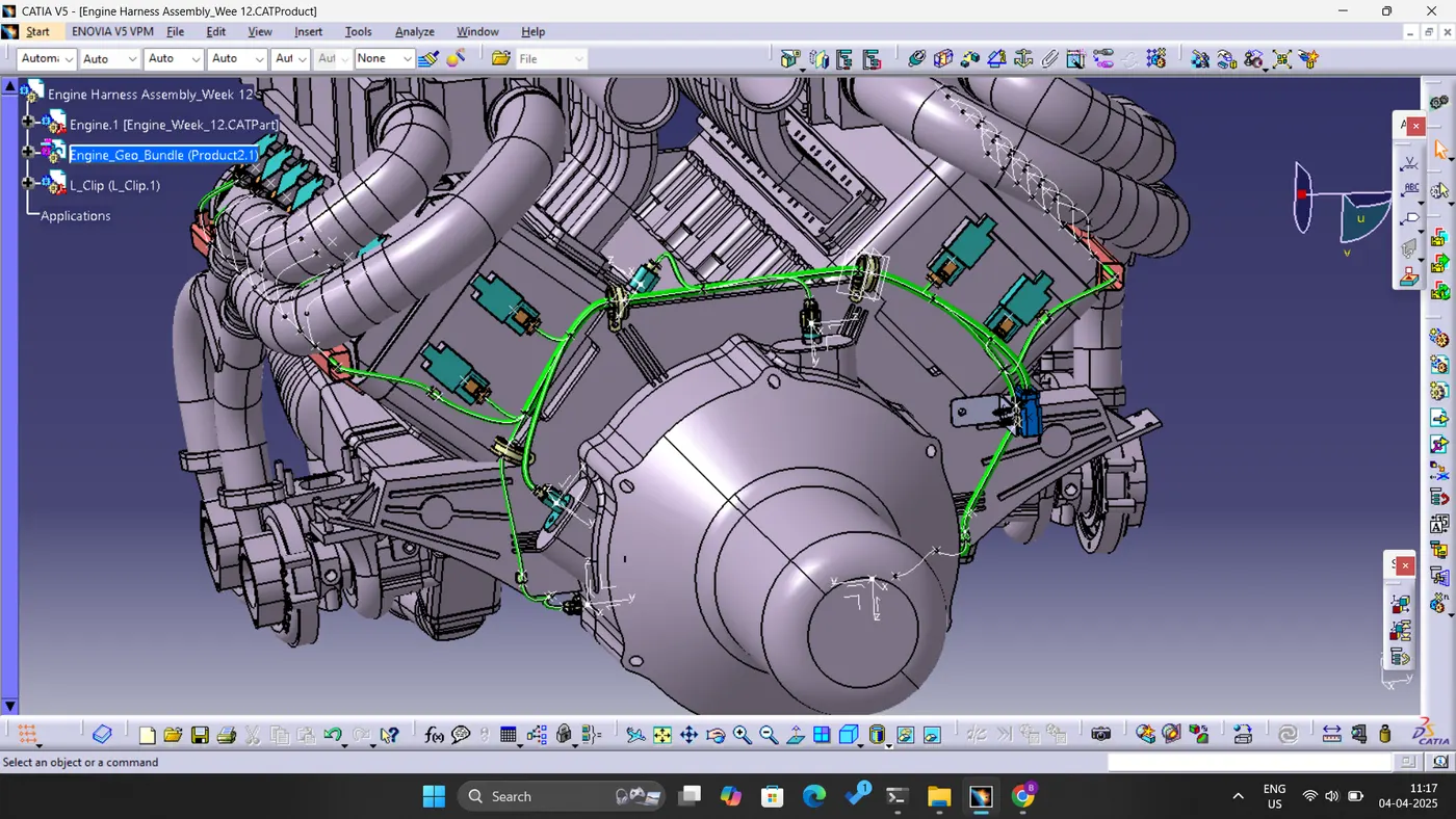
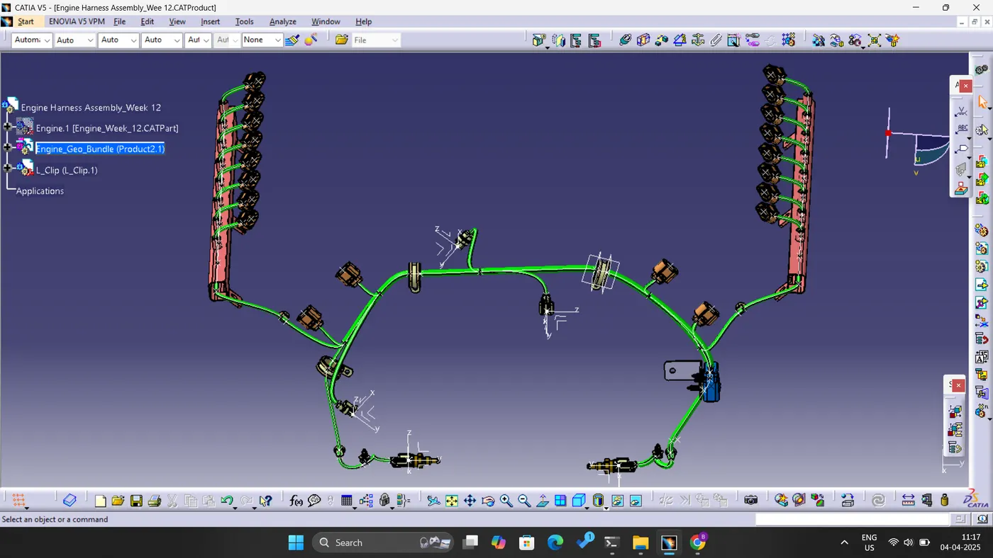
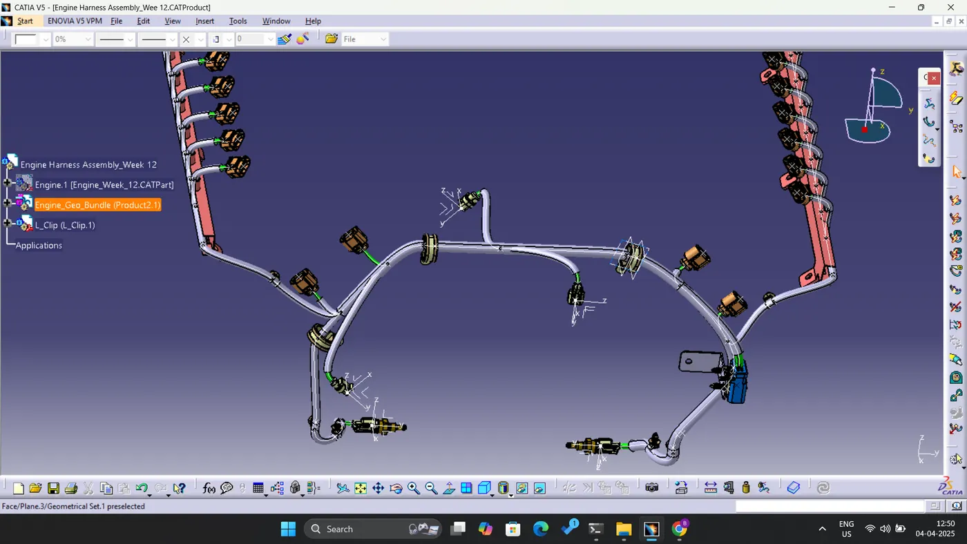
A sheet metal bracket has been designed to facilitate the placement of the interconnection connector in proximity to the engine.
All clamps and fir tree clips have been systematically positioned. Additionally, plastic channels have been installed to connect the injection routing connectors effectively.
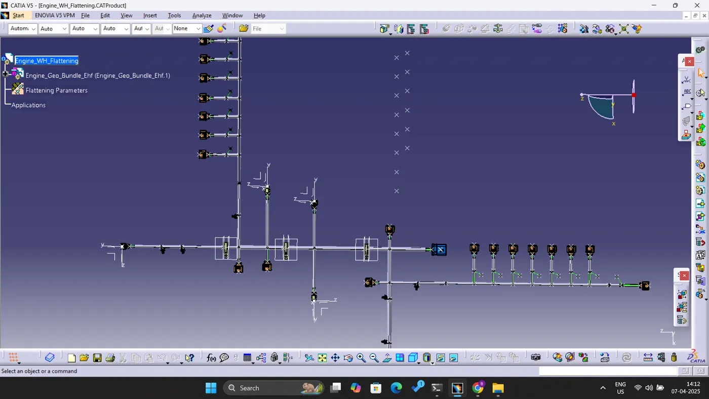
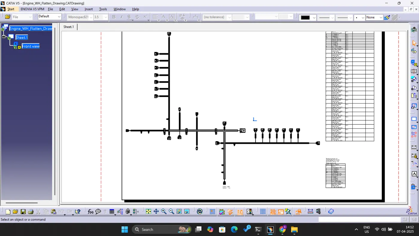
WIRING HARNESS FLATTENING:
As the file size is too big I have attached the google link below: