Challenge

Project 1

Aim of the Project:

  • Build a Simulink model using blocks and complete the vehicle model.
  • Write scripts in MATLAB to load all the variables required for running the Simulink model.
  • Tabulate the fuel economy numbers (Kmpl) for UDDS and HWFET cycles.
  • Plot the time trace for engine speed, transmission input speed, transmission output speed, and wheel speed on one plot.
  • Plot engine torque, engine power, fuel rate, and fuel consumption using subplots.
  • Plot accelerator and brake pedal positions, gear command, vehicle desired and actual speed, and vehicle distance using subplots.
  • Plot the engine operating points on the engine fuel map.
  • Generate the plots for both drive cycles.
  • Study the conventional vehicle Simulink model and create graphs.

Conventional Powertrain Efficiency:

  • Power Generation: The engine converts the chemical energy in fuel into mechanical energy through combustion.
  • Fuel Consumption Formula: The instantaneous fuel consumption is given by:

.mf=Peηe⋅ηt⋅QLHVm.f=Peηe⋅ηt⋅QLHV.mf=Peηe⋅ηt⋅QLHV

Where,
mf = mass flow rate in [kg]

Pe = Power of engine

pt = power of transmission

nt= efficiency of transmission

ne = efficiency of engine

QLHV = it is th eCalorific value/ lower heating value of fuel.

Init File: M-Script: For Initialization of files/Prerequisites for loading the variable for model including Engine & Transmission data:

%% Vehicle Parameters

M = 1500; % Vehicle weight [kg]

Cr = 0.015; % Rolling resistance coefficient

Rw = 0.35; % Rolling radius [m]

Cd = 0.33; % Drag coefficient

Af = 2; % Frontal area [m²]

rhoa = 1.225; % Air density [kg/m³]

Vwind = 0; % Wind velocity [kmph]

g = 9.81; % Gravitational acceleration [m/s²]

theta = 0; % Slope [degrees]

myu_road_tire = 1; % Coefficient of friction between tire - road interface
%% Powertrain Parameters
FDR = 3.73; % Final Drive Ratio / Diff Ratio
DiffEff = 0.99; % Differential efficiency (assumed independent of operating conditions)
NumGear = 4; % Number of gears in transmission
TransGear = [1:NumGear]; % Transmission Gears
TransRatio = [3.06, 1.62, 1, 0.7]; % Corresponding Transmission ratios
TransEff = 0.90; % Transmission efficiency (assumed independent of operating conditions)
TC_SR = [0, .5, .6, .7, .8, .87, .92, .94, .96, .97, 1]; % Torque Converter Speed Ratio -> TurbSpd/PumpSpd
TC_TR = [2.232, 1.5462, 1.4058, 1.2746, 1.1528, 1.0732, 1.0192, 1, 1, 1, 1]; % Torque Converter Torque Ratio -> TurbTrq/PumpTrq
TC_Cf = 1e-4 * [.72558, .66322, .63463, .59042, .51331, .4144, .29287, .22444, .12186, .04386, 0]; % Torque Converter Capacity Factor -> PumpTrq/PumpSpd² [Nm/rpm²]
%% Load Engine and Transmission Data
load('Vehicle_Data/Engine_data_1_9L_Saturn_95kW');
load('Vehicle_Data/Trans_Shift_map');
%% Driver Parameters
Kp = 10; % P gain for driver PI model
Ki = 1; % I gain for driver PI model
Drive_Cycle_Select = 1; % Drive cycle selection (1 for UDDS, 2 for HWFET, etc.)
%% Drive Cycle Data
if Drive_Cycle_Select == 1
load('DriveCycles/UDDS');
elseif Drive_Cycle_Select == 2
load('DriveCycles/HWFET');
elseif Drive_Cycle_Select == 3
load('DriveCycles/FTP');
elseif Drive_Cycle_Select == 4
load('DriveCycles/US06');
elseif Drive_Cycle_Select == 5
load('DriveCycles/NEDC');
elseif Drive_Cycle_Select == 6
load('DriveCycles/WLTP');
end
% Set end time and velocity of the cycle
time_end = cyc_time(end);
vel_end = cyc_vel(end);

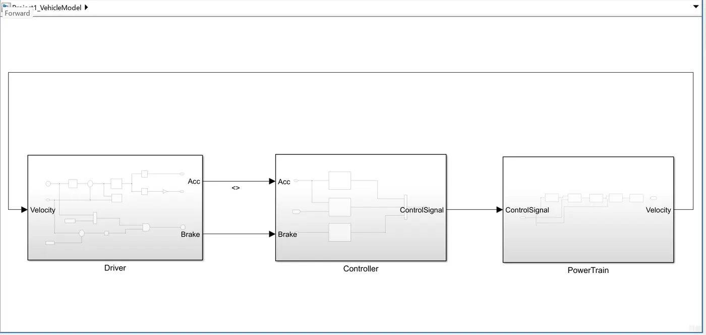
MATLAB Model: Includes Driver, Controller and PowerTrain modules.


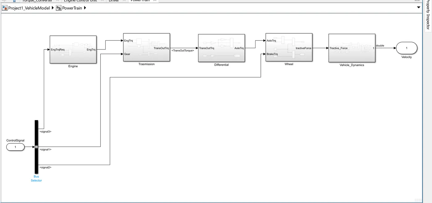
1.PowerTrain: The powertrain includes the engine, transmission, torque converter, differential, and driveshaft. It converts the engine's power into tractive force, propelling the vehicle. The powertrain's efficiency and performance directly influence the vehicle's fuel economy, acceleration, and overall driving experience.


1.1.Vehicle Dynamics: Formula used here to model for vehicle dynamics

MeqdVvehdt=ηtλtotRwTm−(12p⋅A⋅Cd⋅(Vveh+Vw∈d)2+Cr⋅M⋅g⋅cos(θ)+M⋅g⋅sin(θ))MeqdVvehdt=ηtλtotRwTm-(12p⋅A⋅Cd⋅(Vveh+Vw∈d)2+Cr⋅M⋅g⋅cos(θ)+M⋅g⋅sin(θ))MeqdVvehdt=ηtλtotRwTm−(12p⋅A⋅Cd⋅(Vveh+Vw∈d)2+Cr⋅M⋅g⋅cos(θ)+M⋅g⋅sin(θ))

Where:

  • Pp = air density [kg/m³]

  • AA = frontal area [m²]

  • CdC_d = drag coefficient

  • VvehV_{veh} = vehicle velocity [m/s]

  • VwindV_{wind} = wind velocity [m/s]

  • CrC_r = rolling resistance coefficient

  • MM = mass [kg]

  • gg = gravity

Then we calculate and integrate then we meet acceleration of vehicle and velocity of vehicle it mean vehicle distance and vehicle speed.
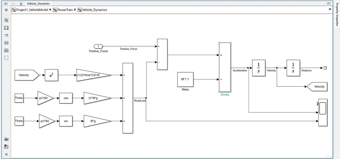


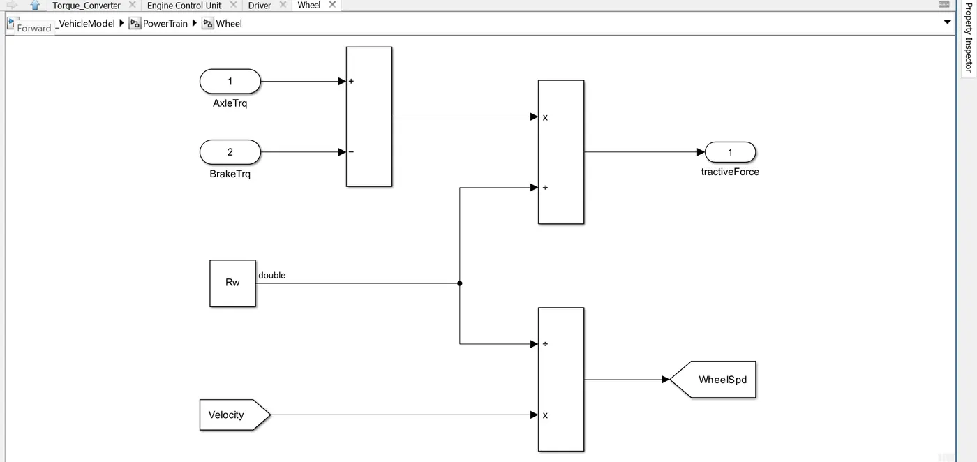
1.2.Wheel: The wheel is a crucial component of the vehicle, translating the tractive force from the powertrain into motion. It consists of the tire, rim, and hub, and interacts with the road surface. The wheel's design, including its radius and tire characteristics, directly influences traction, handling, and ride comfort.

In this model we take the axle torque from differential and brake torque from controller. it is subtracts and multiplied rolling radius and velocity then we meet the tractive force from axle and brake torque. and the wheel speed is meet using velocity.
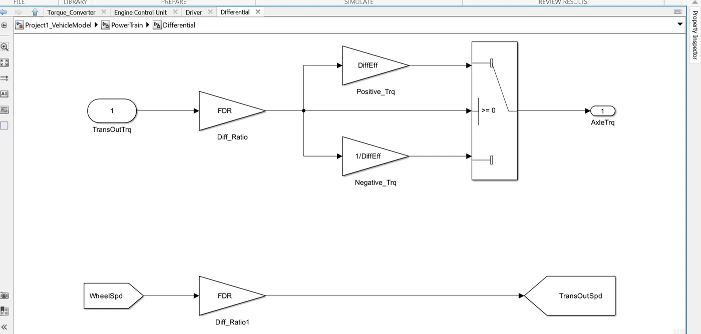


3.Differential: In this taking input is the transmission output then its going to the differential ratio multiplied the output and input torque then meet axle torque. The axle torque is a lower than the transmission torque and differential ratio.


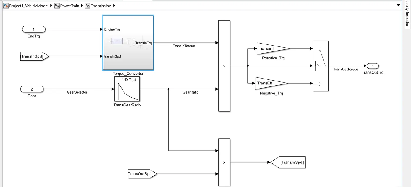
4.Transmission: In these model we take engine torque, gear selector from controllerb for transmission of gear ratio. The ratio is multiply by transmission input torque and then the transmission efficiency positive torque and negative torque gives transmission input speed. In this case torque converter connects the engine to transmission it is part of transmission. In it basically engine dynamics and that is decoupled.


4a. SubSystem for torque Converter
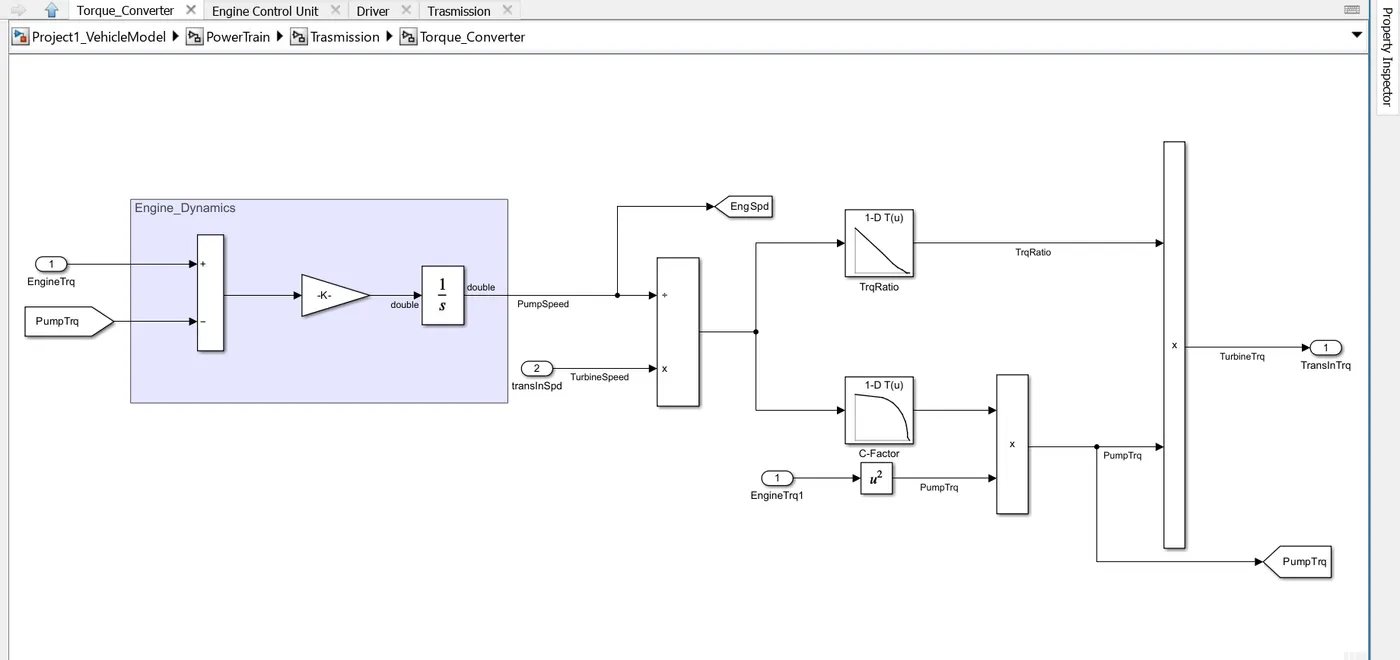

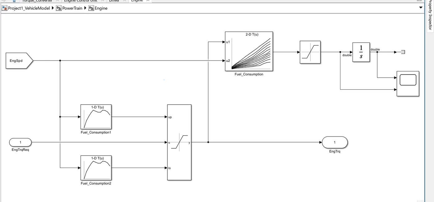
5.Engine: In this model we used map based model to model the fuel consumption of engine. It is based on maximum Torque and minimum torque from the controller. and then it saturated torque and give output then saturated torque and speed map give fuel consumption takes the speed and torque then the output goes into saturated then its integrated.


2.Controller: The ‘Controller’ block is the brains of the vehicle, representing the electronic controls units. It is based on the driver inputs, it generates desired engine torque, desired transmission gear and desired brake torque. These inputs are fed to the ‘Powertrain’ block which represents the drivetrain of the vehicle.
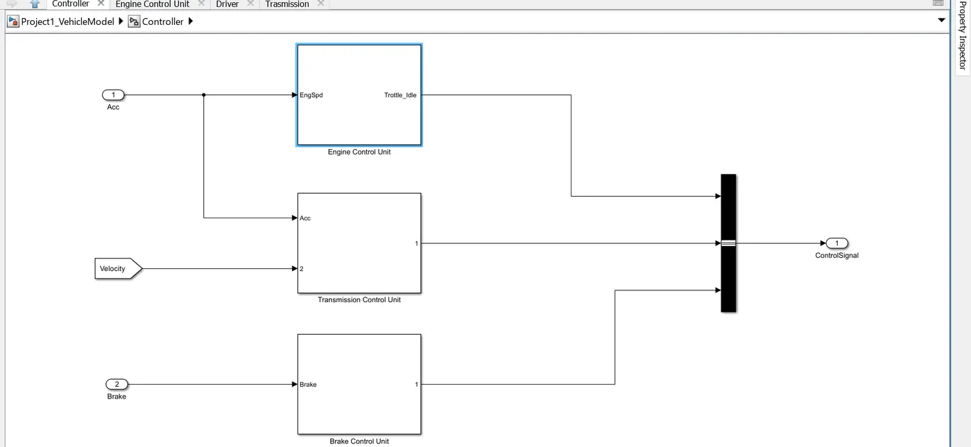


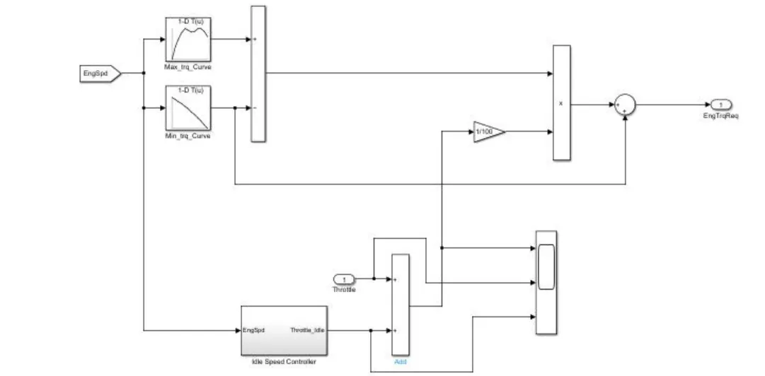
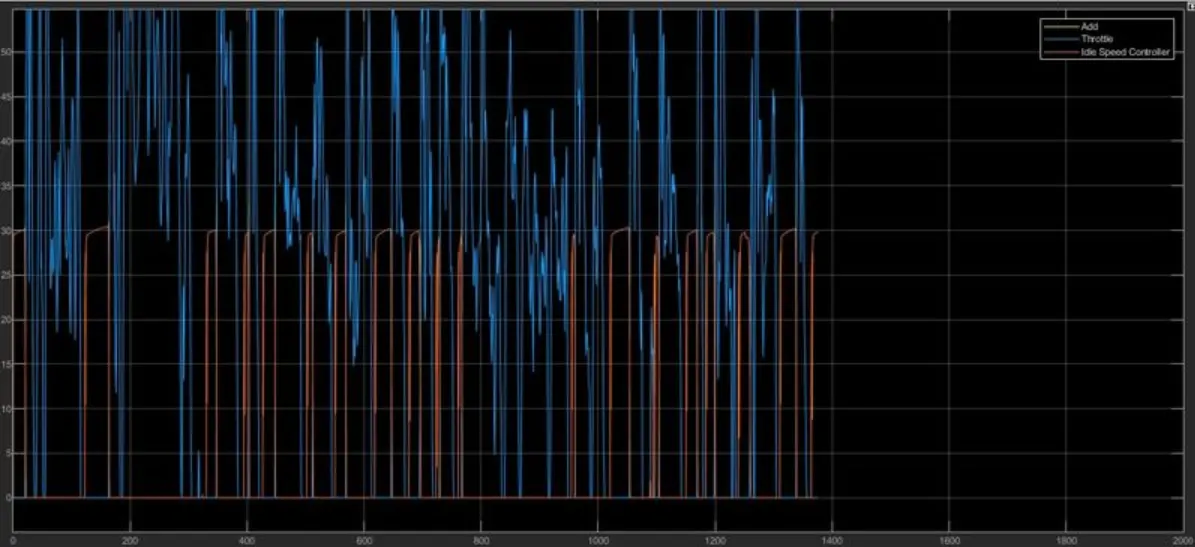
2.1. Engine Control Unit: In this control model, we utilize the Engine Control Unit (ECU) by inputting engine speed through a lookup table. This table includes inputs for maximum torque and mapped speed. Additionally, a second lookup table is created with inputs for current torque and mapped speed, which are subtracted and then multiplied. The engine speed is also provided to an idle control speed to integrate, resulting in the output of the required engine torque.

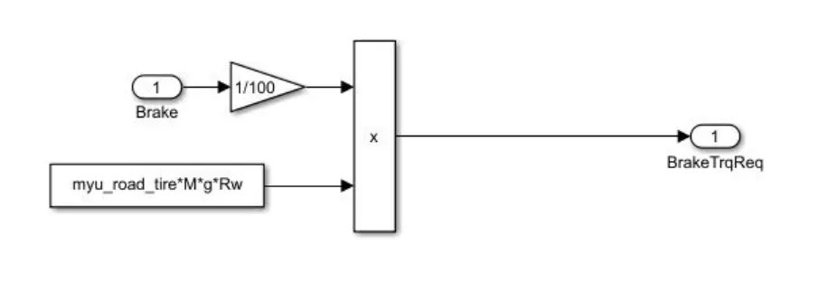
2.2. Transmission Control Unit: In this unit, we calculate the brake torque and provide all three control signals (engine torque, transmission gear, and brake torque) to the powertrain. This ensures that the vehicle's acceleration, deceleration, and gear shifting are managed effectively for optimal performance.

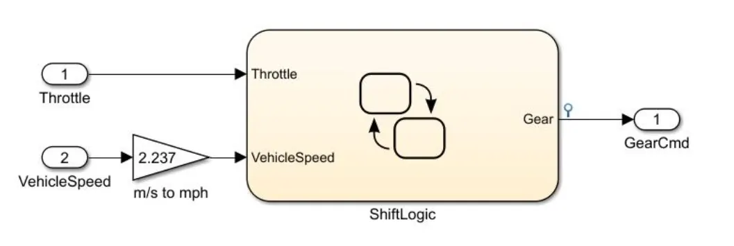
2.3. Brake Control Unit: In this unit, we establish a steady flow variable state to control the vehicle's gear shifts in ascending and descending order based on time, speed, and distance. The input for this steady state is the vehicle speed, converted from meters per second (m/s) to miles per hour (mph).

Engine Control UnitTransmission Control Unit Brake Control Unit


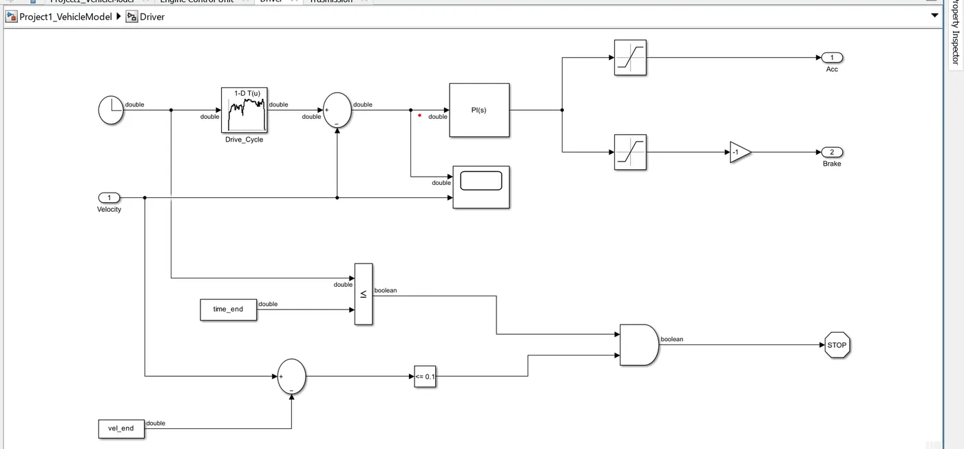
3.Diver: It is modeled using a ‘Driver’ block, which is a basic PI controller that generates accelerator and brake pedal outputs to match the desired and actual vehicle speeds. Drive cycles are employed to evaluate fuel consumption and emissions, aiding in vehicle certification and providing a basis for uniform assessment. The model integrates time and velocity data to produce acceleration and brake pedal outputs, ensuring accurate simulation of vehicle dynamics.


Graphs: Input is Taken from adding scope block in model

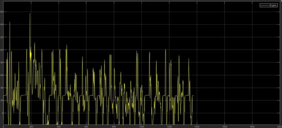
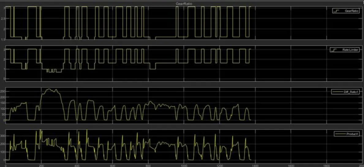
Engine Torque (Driver Model)Drive /driver Model Transmission speed, Gear ratio, Differential Ratio


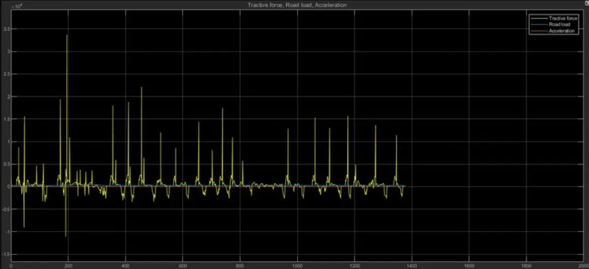
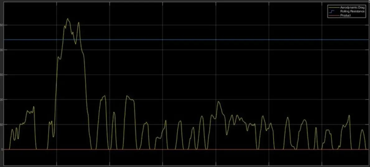
Road load, Acceleration, Tractive forceRoad load

Your portfolio, next

Ship work like this
in your own course.

Talk to a career counsellor

Free 20-minute call. We'll map the right course to where you want to work.

By submitting you agree to our Terms and Privacy Policy.