Project 1
Aim:- Create a stateflow or Simulink model for the following flowchart.
Load the .mat file into the workspace.
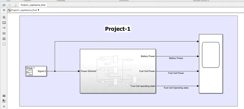
The input to the model would be the power demand.
The output should be:
- Fuel cell power
- Battery power
- FC Operating state (running, standby)
Create plot of these outputs against time.
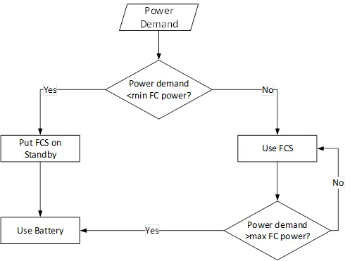
(Note- The simulink model file should be compulsorily attached)
Answer:-
Simulink Model:-
For given flowchart:-
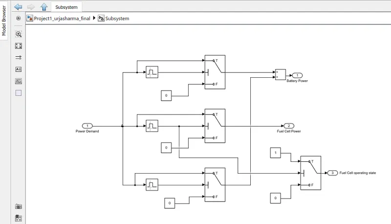
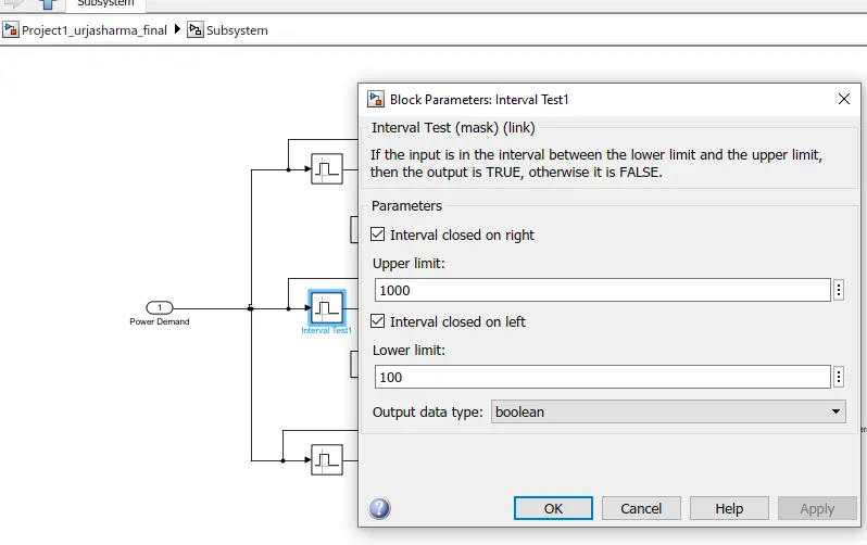
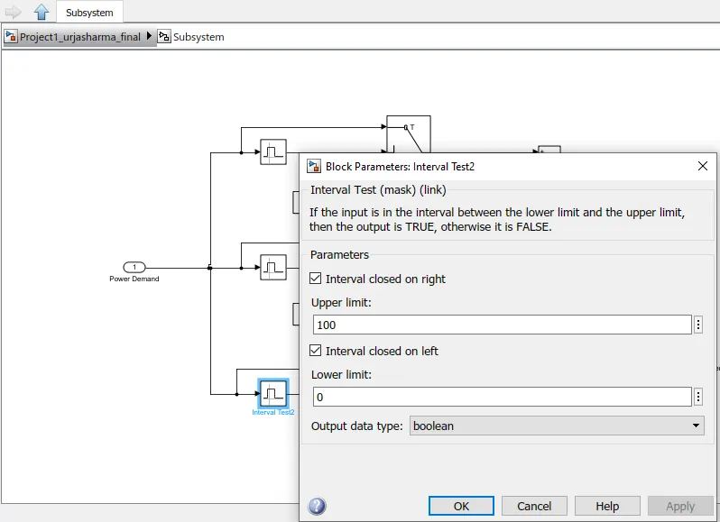
Parameter Settings:-
1)
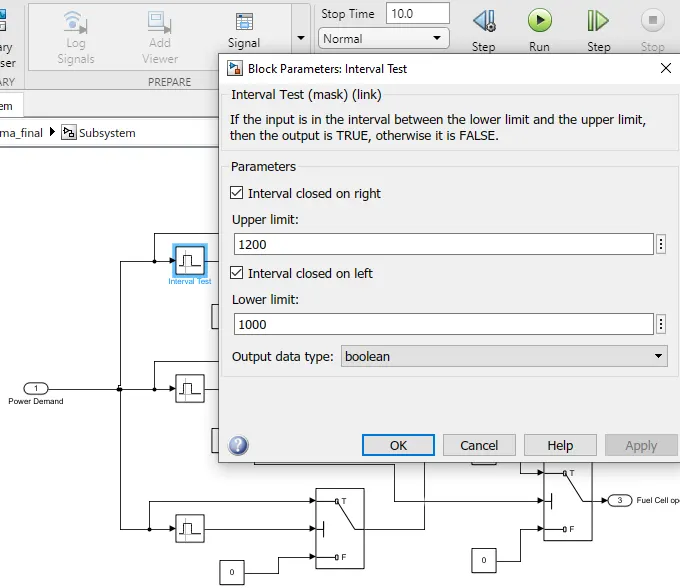
2)
3)
Results:-
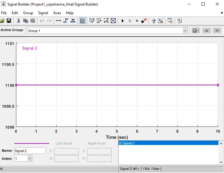
For 1100 Power Demand:
Input:-> Power Demand
Output:-
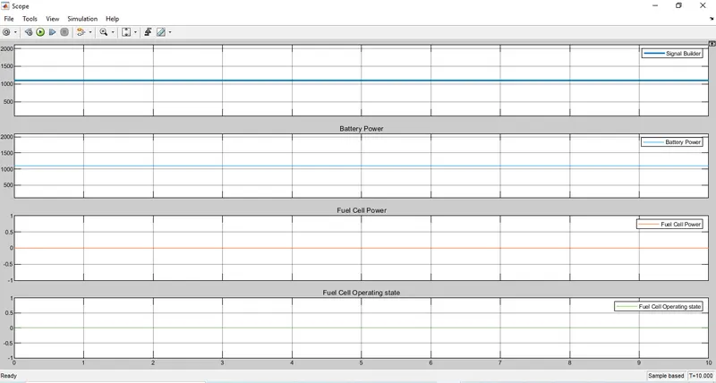
As per our logic if the power demand is <1200 and >1000, It will choose battery. Here in above result we can observe that the battery is providing 1100 power.
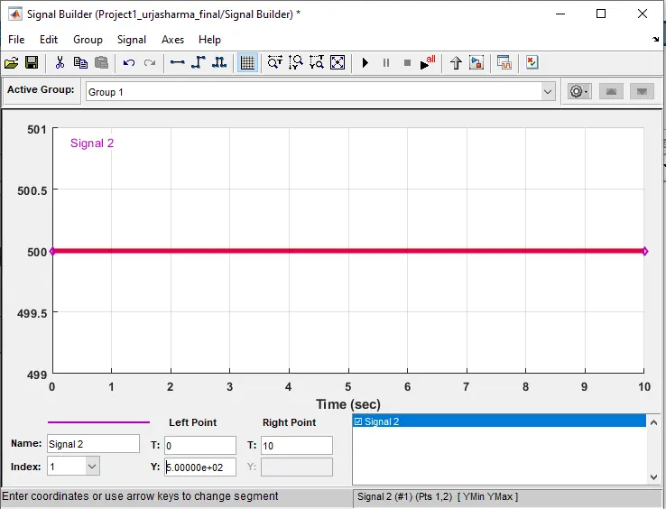
For power Demand 500:-
Input:-> power demand
Output:-
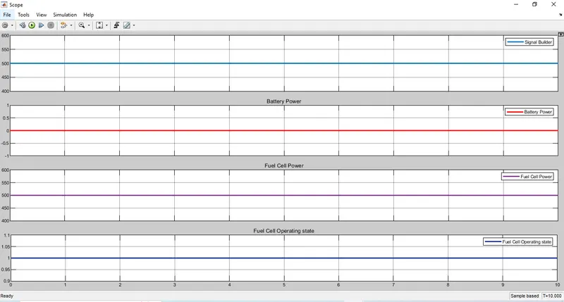
Now as per logic if power demand is <1000 and >100--> it choose fuel cell and the state of fuel cell become 1.
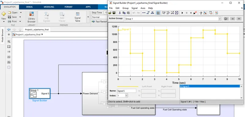
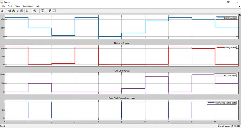
Now for variable power demand input:-
Output:-
Conclusion:-
Here we have prepared the simulink model for the given flow chart. We simulated the requirement of battery or fuel cell as per the power demand. We can observe that as per the power demand we can switch from battery to fuel cell and viceversa. The results are plotted for Battery power, fuel cell power and fuel cell operating stage.