Project 1
PROJECT
ANALYSIS AND DESIGN OF A G+6 RESIDENTIAL BUILDING IN BANGALORE
INTRODUCTION:
With the advancements in software technology, the analysis and design of buildings have become much more simplified than before. The overall process of building design has been shortened with the automated calculations included in software like Staadpro, ETABS, SAP2000, and many more. Moreover, the reinforcement detailing for all structural members has also been automated by the latest Staad RCDC tool.
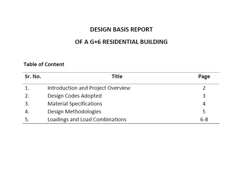
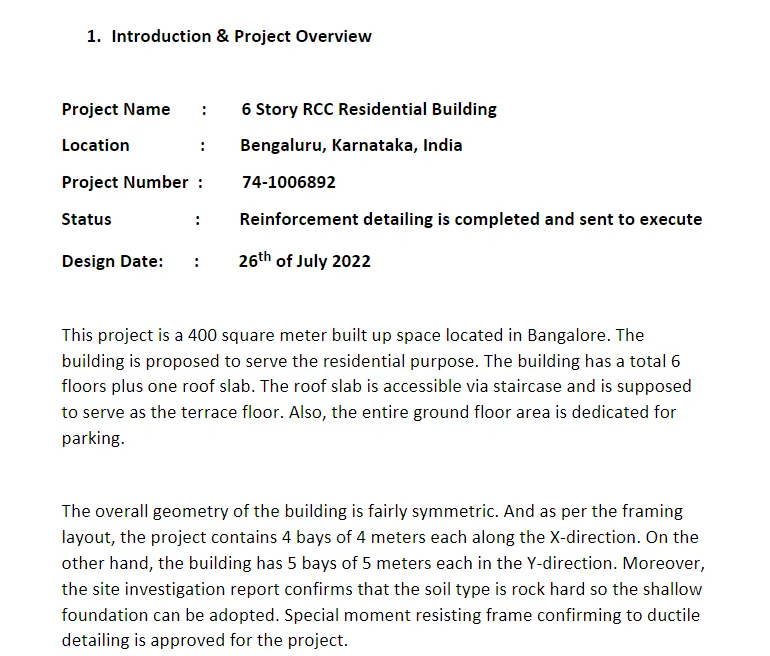
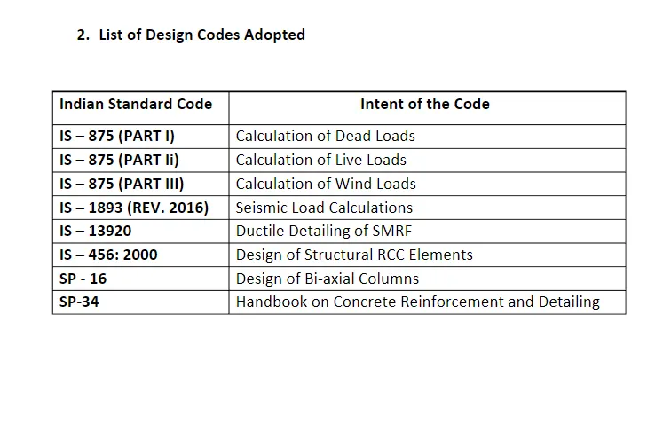
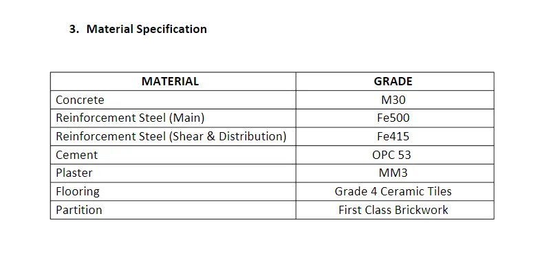
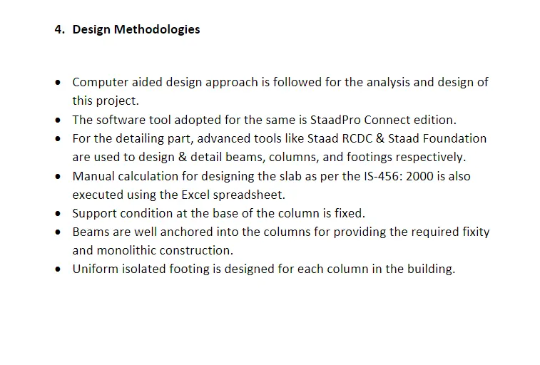
So, in this project, we have completed the entire design process from start to finish with the help of Staad Pro. At the same time, we have also followed the automated reinforcement detailing with Staad RCDC. This project is divided into three phases. In the first phase, the analysis part is covered from start to end including the modeling, application of human and environmental loads, and running of the analysis. Then, in the second part, the design, and detailing of the building are carried out extensively. In the end, a comprehensive design basis report formally known as 'DBR' is prepared following the industry standards.
TOOLS USED:
- StaadPro Connect Edition
- Staad Foundation
- Staad Advance Concrete Designer (RCDC)
- MS Excel (Manual Design of Slab)
- MS Word (Design Basis Report)
EXECUTION:
PHASE I: Complete Modeling and Analysis of the Building
- Model the Building Frame Based on the Architectural Layout
1. Open StaadPro> go-to structure wizard> set units to SI> select RCC bay frame> specify the building dimensions.
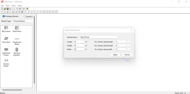
2. Hit apply and the frame will be generated automatically.
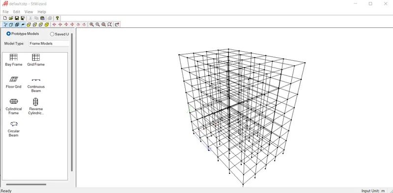
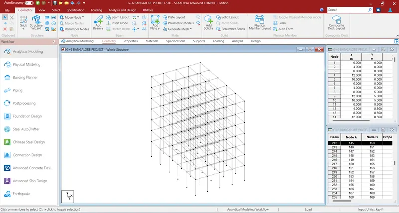
3. Merge the structural frame with the current Staad model from the file menu.
- Define the Material and Sections to be Used for the Frame
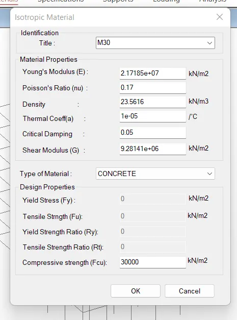
1. Go to materials> add> concrete> specify the compressive strength M30>ok.
2. Go to properties>add section> specify rectangular shape> enter beam dimensions> ok.
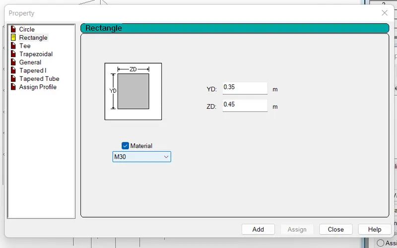
3. Repeat the process for columns.
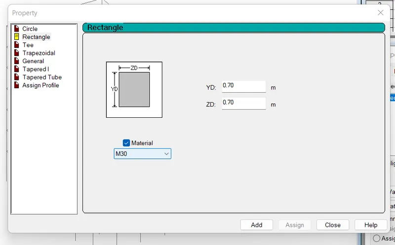
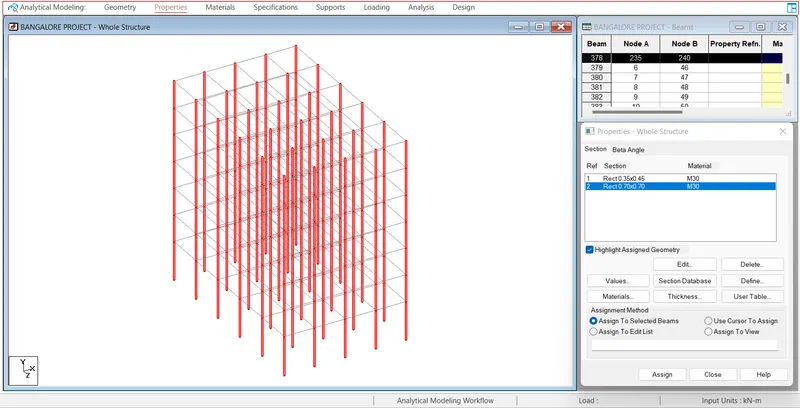
4. Select parallel to Y and assign the column to selected sections.
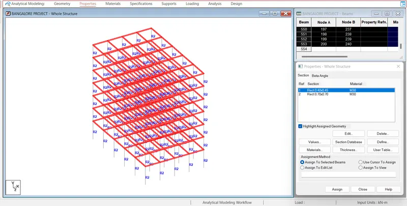
5. Select parallel to X and Z and assign the beam to selected sections.
6. Go to elevation select all the nodes at the base level and assign them fixed support after adding it from the supports panel.
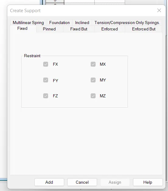
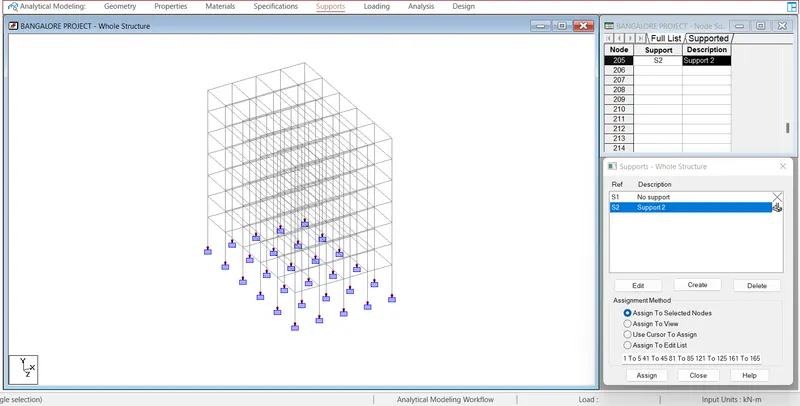
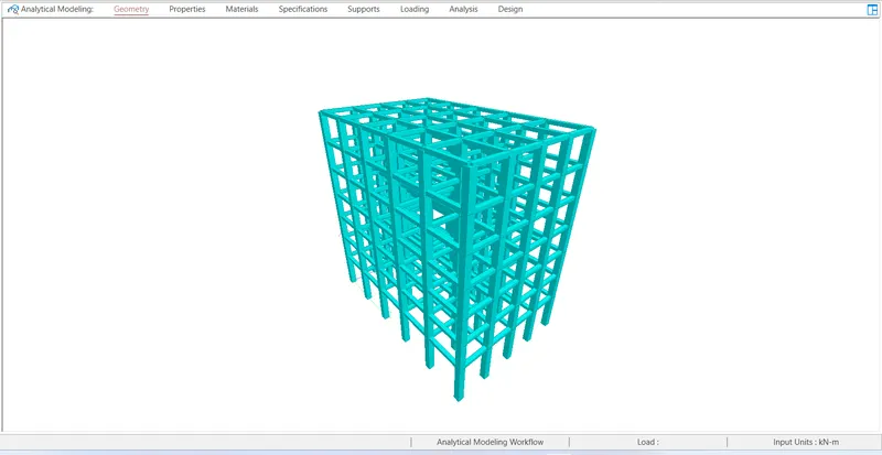
7. Generate the 3d rendered view of the building and inspect for any errors.
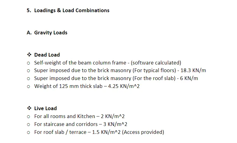
- Gravity Load Application
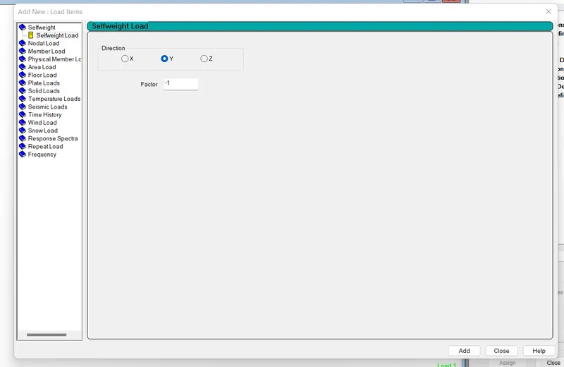
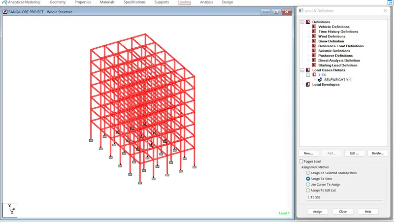
1. Define and assign the dead load case for self-weight.
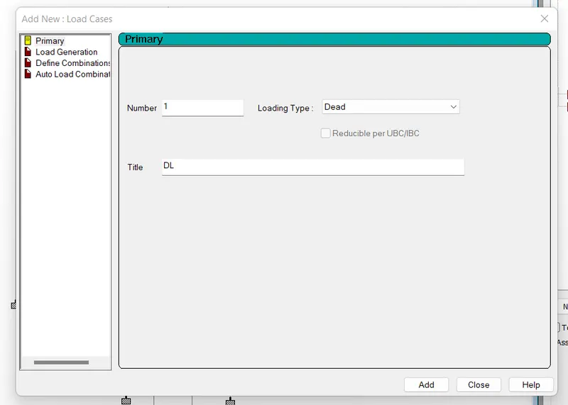
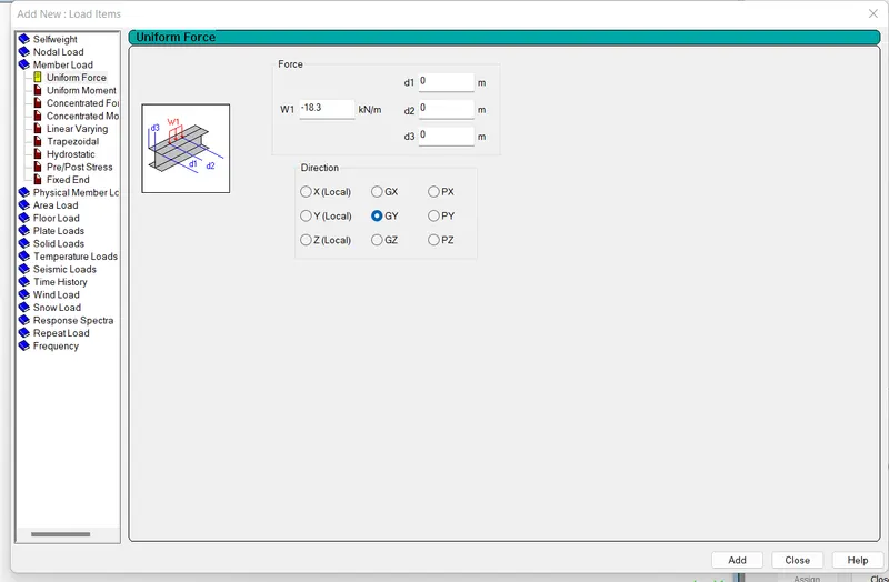
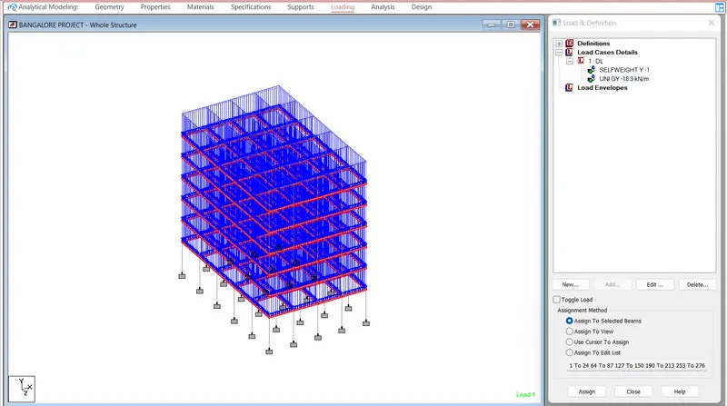
2. Define and assign superimposed brick wall load for typical floors.
3. Superimposed load for the roof slab.
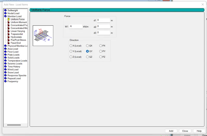
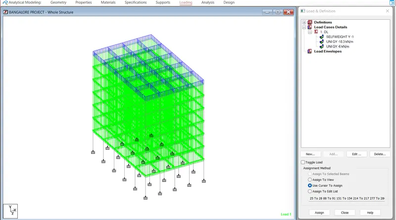
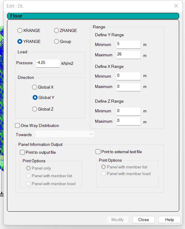
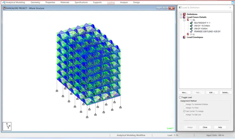
4. Dead load due to the slab.
5. Live load for typical floors as per the IS-875.
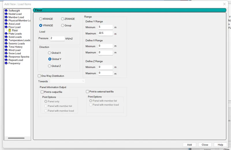
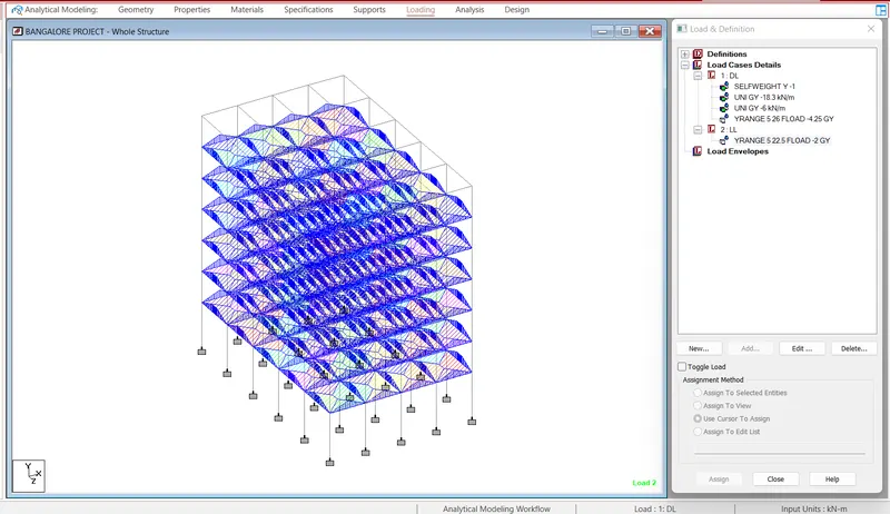
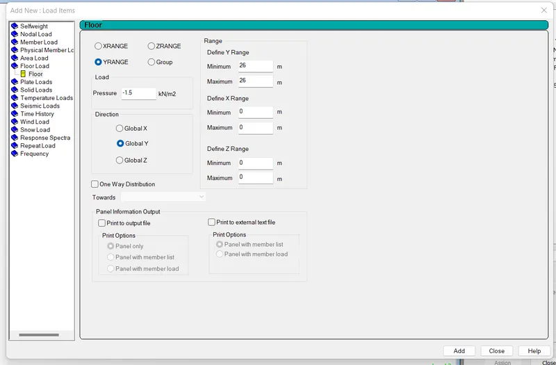
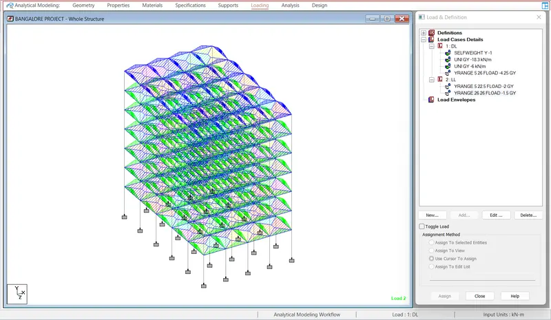
6. Live load for the roof slab.
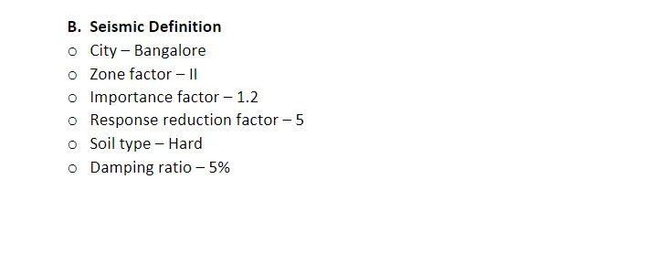
- Application of Seismic Loads
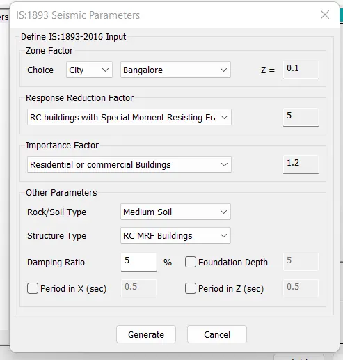
1. Define the seismic parameters like zone factor, importance factor, time period, etc.
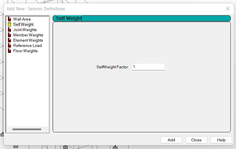
2. Add the seismic weight of the building.
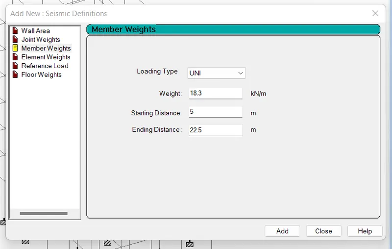
3. Add member weight for typical floors.
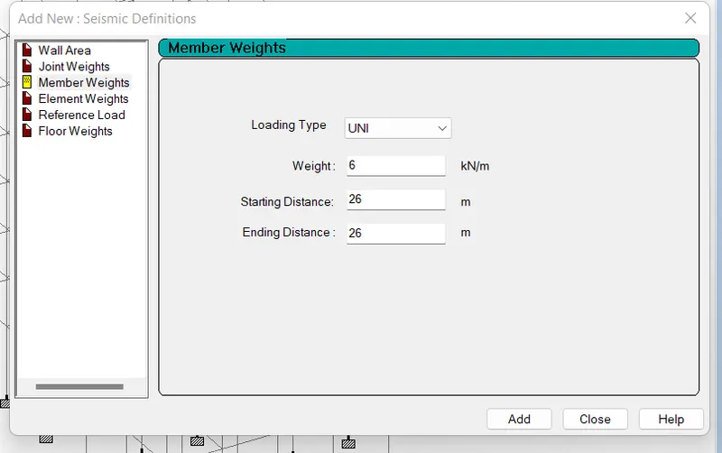
4. Add member weight for the roof slab.
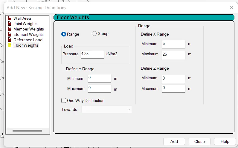
5. Add floor weight
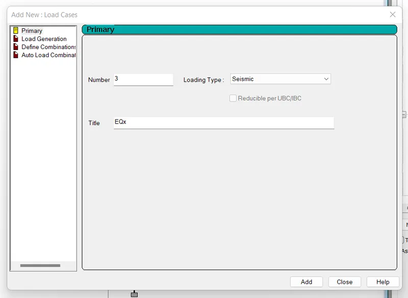
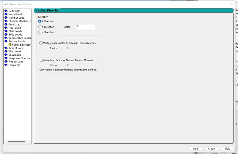
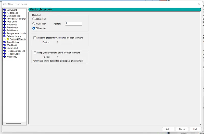
6. Earthquake Load in the X direction.
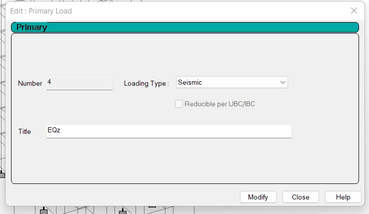
7. Earthquake Load in the Z direction.
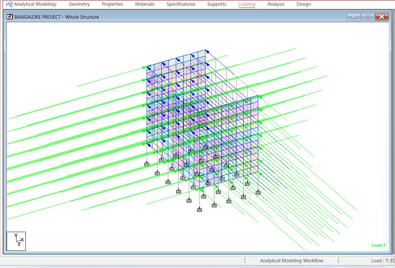
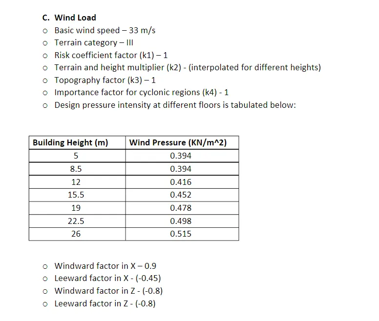
- Wind Load Application
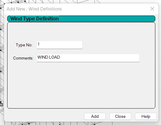
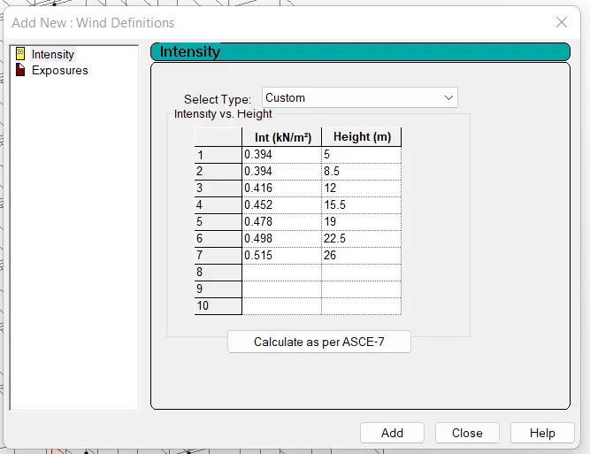
1. Define the wind load and enter the wind intensity at different heights as calculated in accordance with the IS - 875 (PART III)
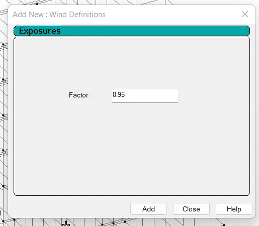
2. Add the wind load case in X with the appropriate exposure percentage.
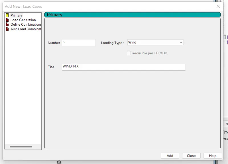
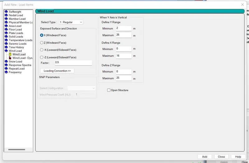
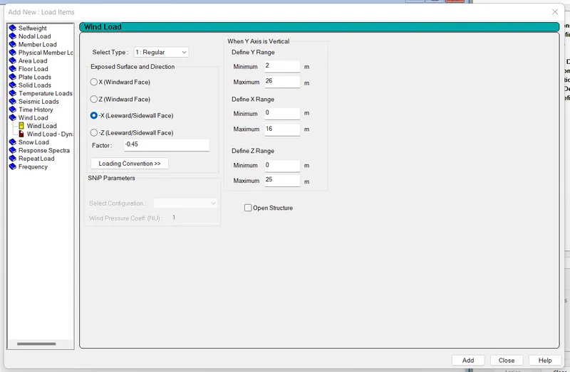
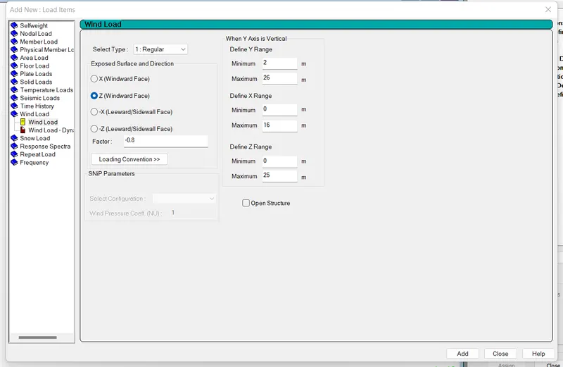
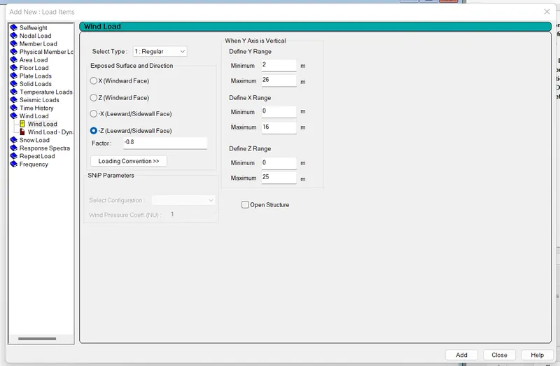
3. Add the wind factor in both the windward and leeward directions as follows:
X-Windward
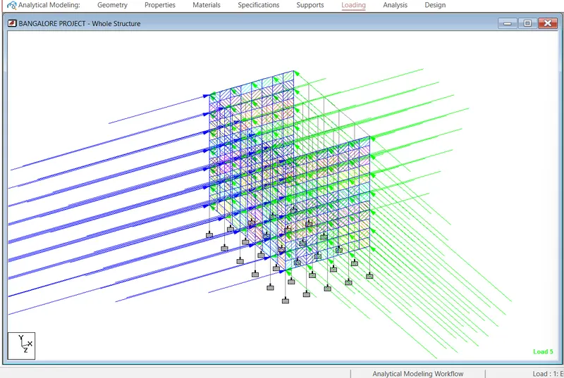
X-Leeward
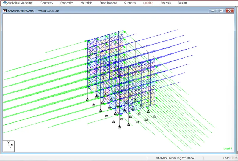
Z-Windward
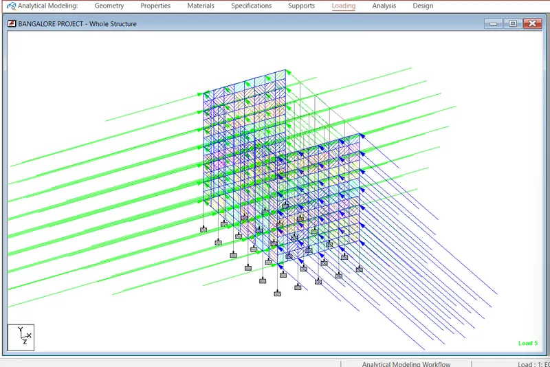
Z-Leeward
- Run the Analysis
Now that all the loads have been applied to the building, add the analysis command and run the analysis in StaadPro.
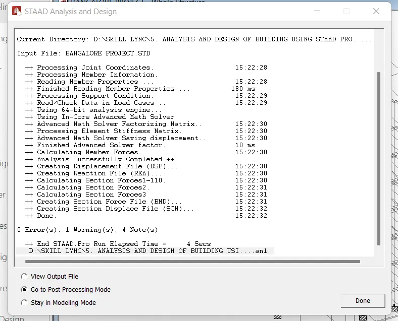
After completing the analysis, phase one of our project has been completed and now we have to execute the design and detailing of the structural members.
PHASE II: DESIGN AND DETAILING OF STRUCTURAL MEMBERS
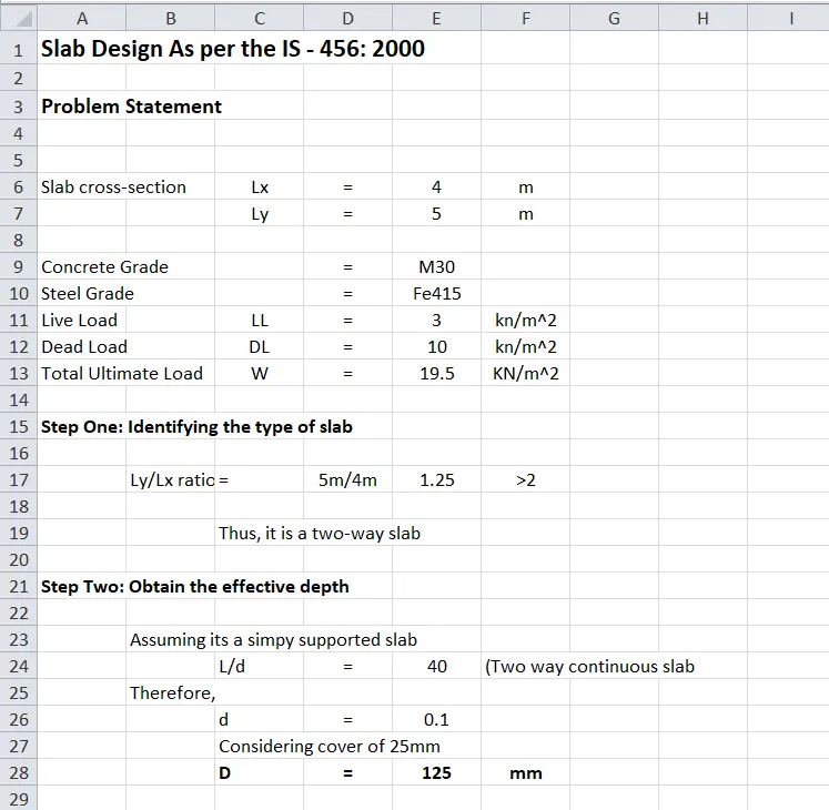
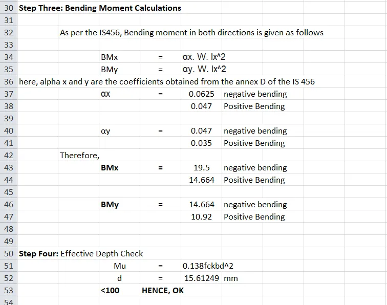
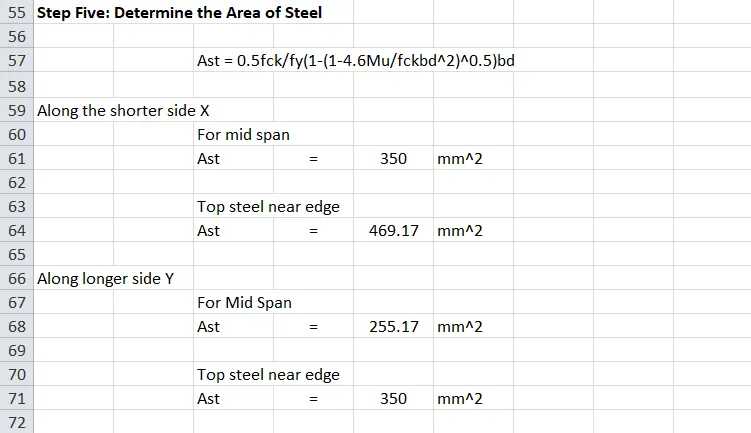
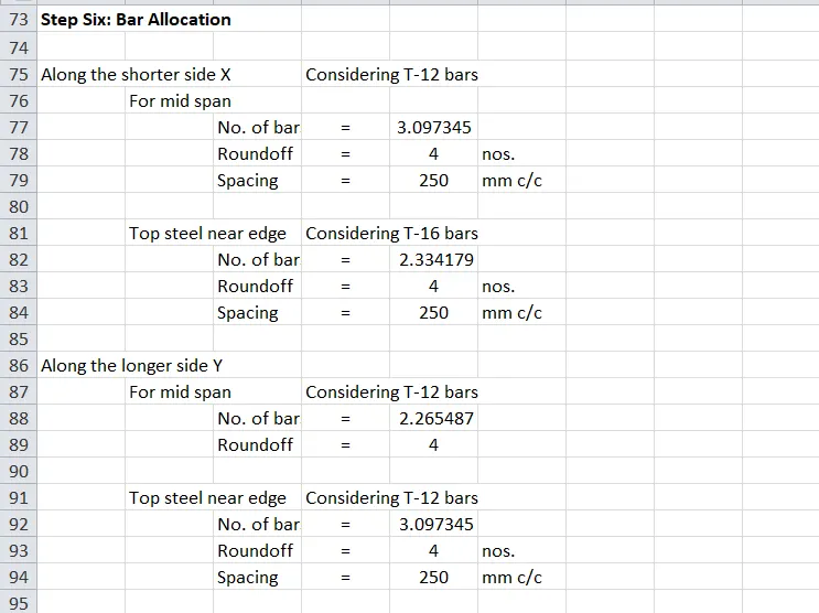
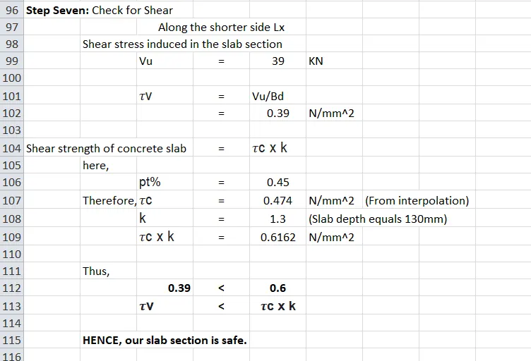
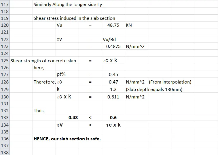
- Manual Design of Slab using MS Excel
- Design of Beam Using Advance Concrete Designer (RCDC)
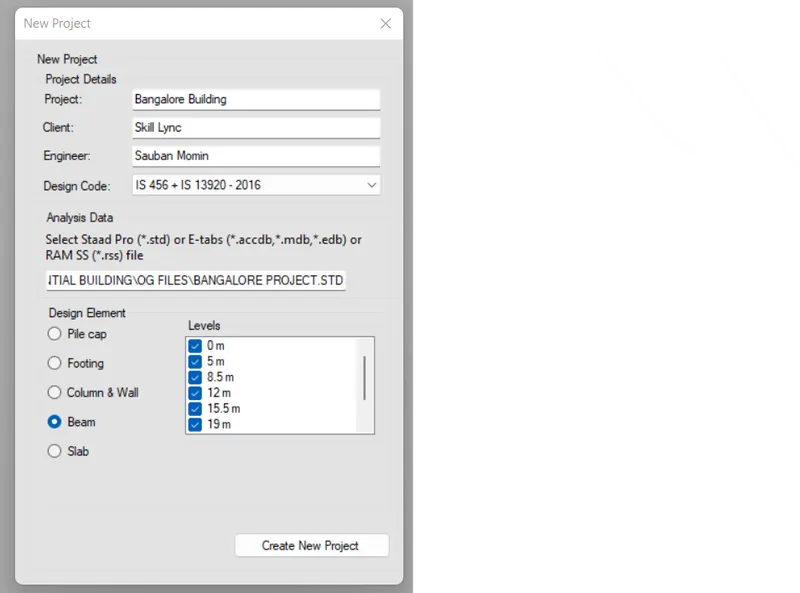
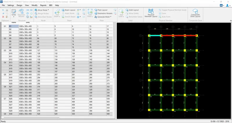
1. Open the concrete designer and initiate the project by merging your Staad model.
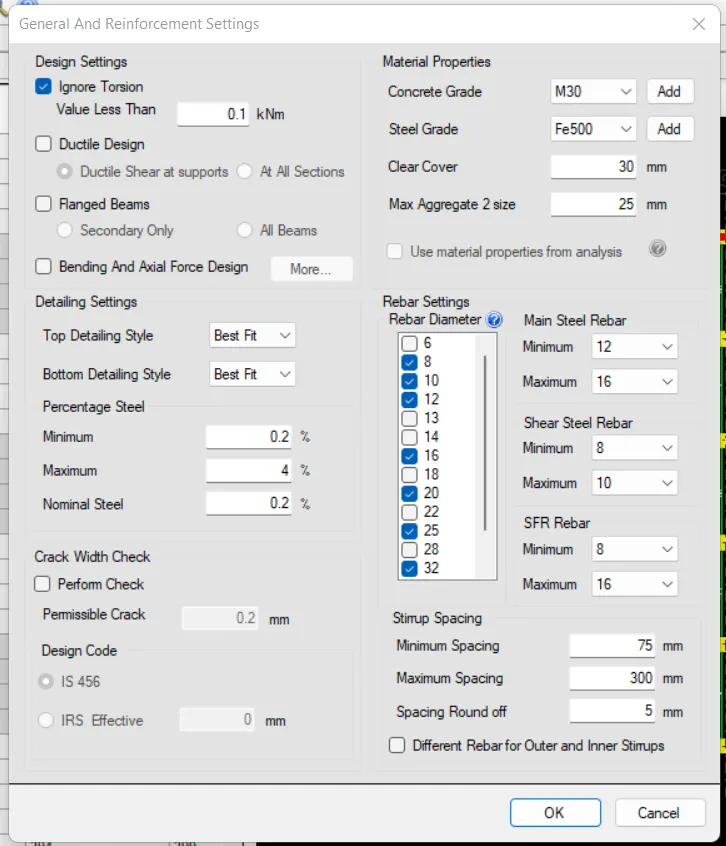
2. Execute the general reinforcement settings as per the design intent.
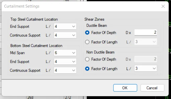
3. Add up the curtailment details.
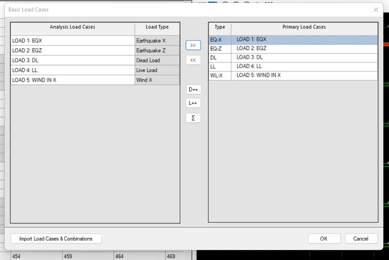
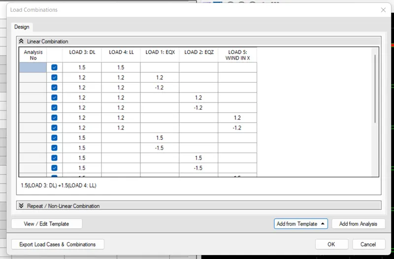
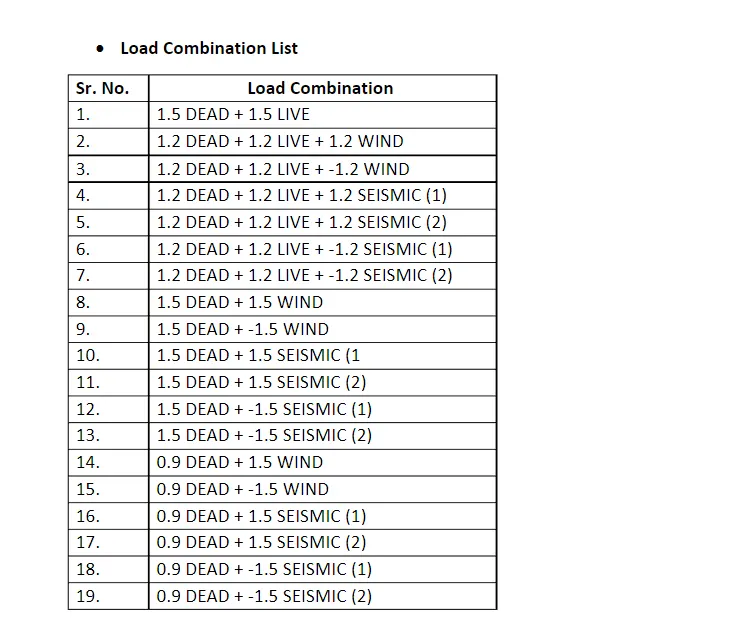
4. Acquire all the loads and combinations from your Staad Analytical model.
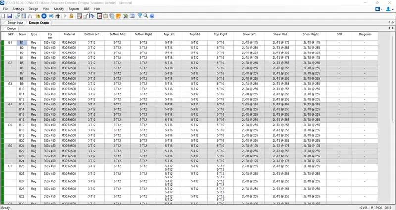
5. Run the automated design.
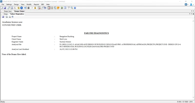
6. Run the failure diagnostic to check if all members have passed.
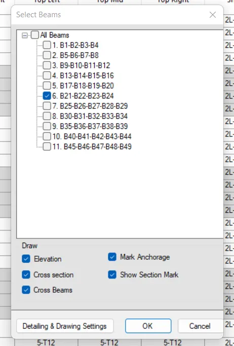
7. Now, go to the report section to generate the reinforcement detailing of the desired beam.
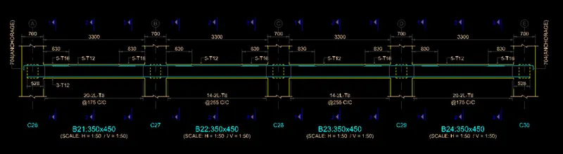
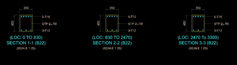
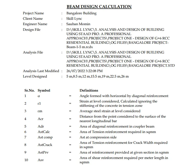
8. Go through the calculation sheet to understand the overall design process.
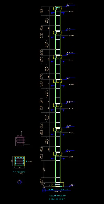
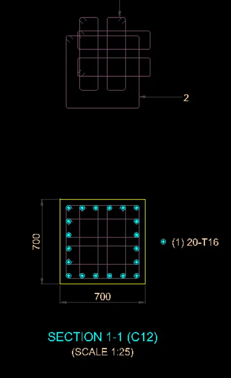
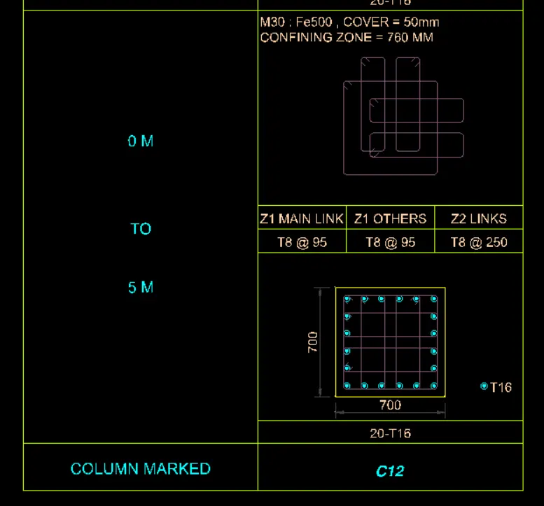
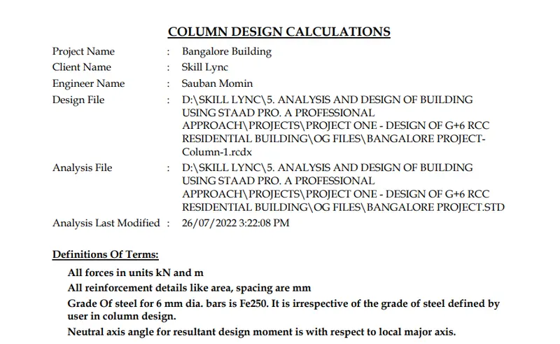
- Column Design Using RCDC
*Column design can be carried out in an exact manner followed for beam. So, the same is done and the final column details are inserted below:*
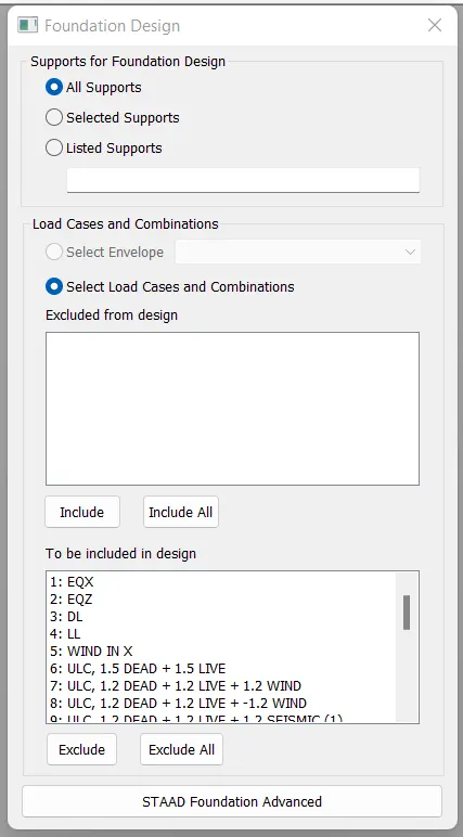
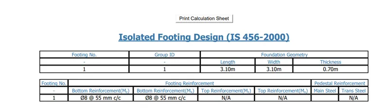
- Design of Isolated Footings Using Staad Foundation
1. Initiate the project by including all the load cases from your Staad model.
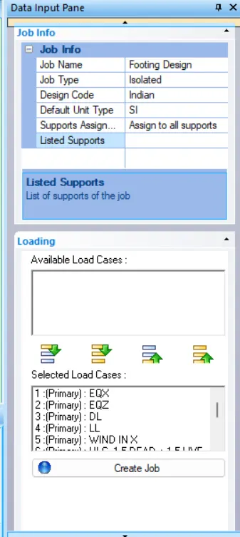
2. Create a new job for designing the isolated footings.
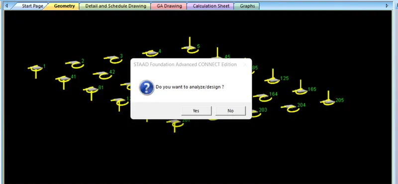
3. Run the automated design.
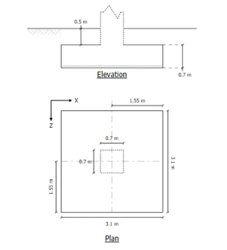
4. Generate detailed footing drawings.
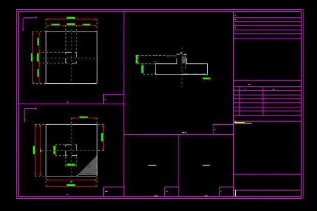
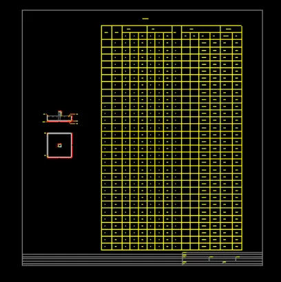
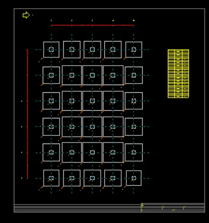
5. Go through the calculation sheet.
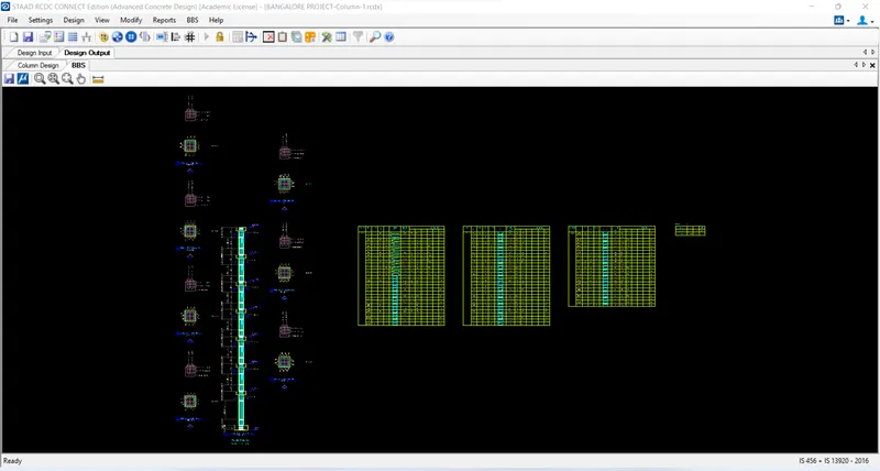
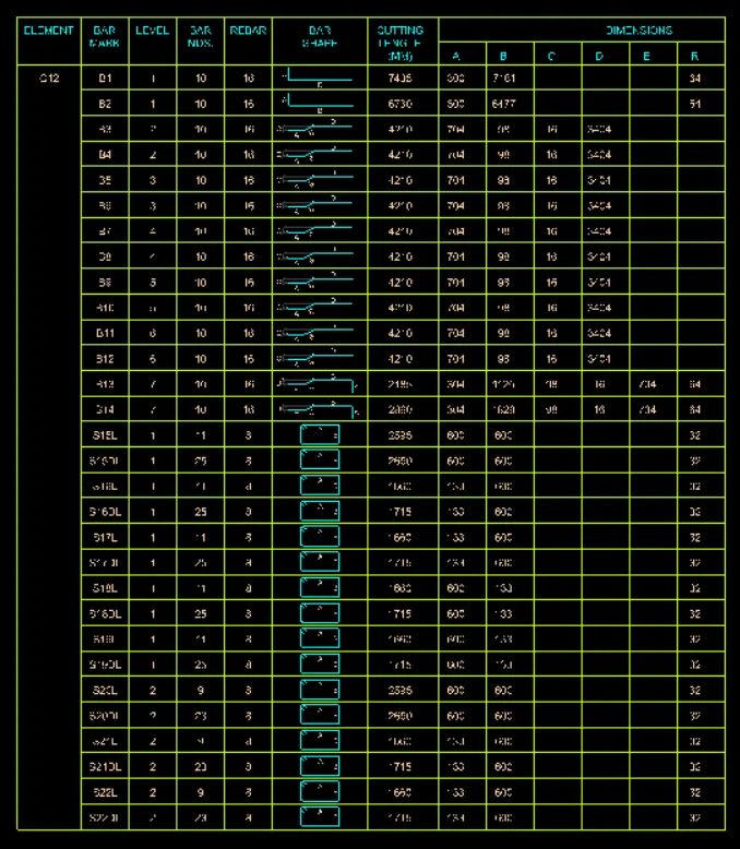
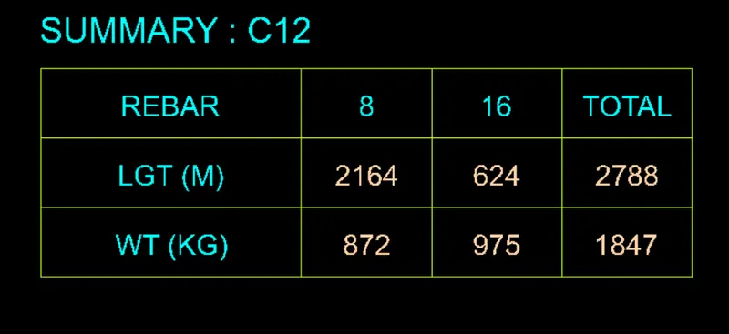
- Generating the Bar Bending Schedule for Beams & Columns
1. Click on the BBS option within Staad RCDC.

2. Setup the BBS parameters in accordance with the codal norms.
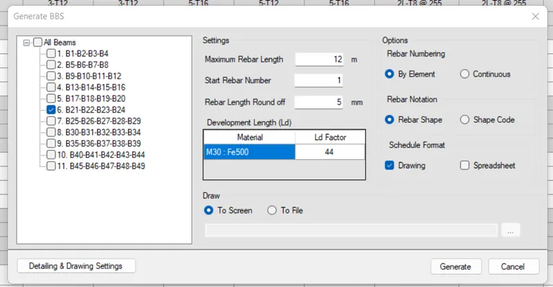
3. Generate all the drawings as inserted below:
BBS for Beam
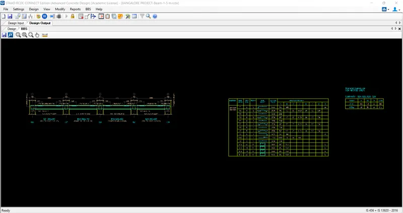
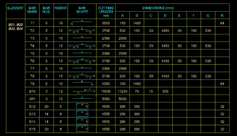
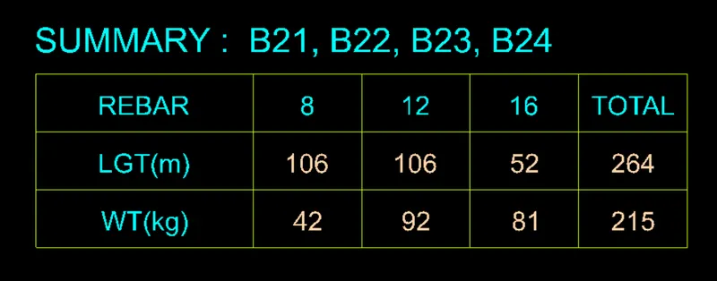
BBS for Column
PHASE III (FINAL PHASE): WRITING UP THE DESIGN BASIS REPORT USING MS WORD
PROJECT CONCLUSION:
As can be seen from the executed project, the entire structural design workflow has been simplified with the introduction of advanced computational tools like StaadPro. All you need to know is how to feed the correct details of a project, and the software takes care of the rest. However, one has to be conceptually sound and must be aware of all calculations being carried out behind the software for a proper structural design of different buildings.